Project pathway
The quickest route to the right decision.
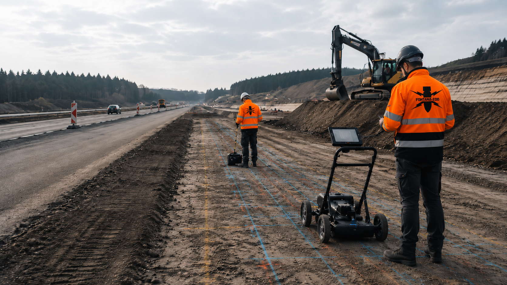
Before roadworks and civil-engineering work, the route, utility trench, excavation and deep foundations are compared with available ordnance indicators. FONTANA-EOD reviews the documents and planned ground interventions. Send the site plan, intervention depths and construction phases so that suitable investigations and evidence can be defined for the individual road sections and structures.
Assign sections, structures and crossings.
Represent excavation, retaining works and foundations.
Clearly document the areas dealt with.
In roadworks and civil engineering, ordnance assessment is based on the planned ground intervention and available suspicion and investigation records. Road corridors, utility trenches, excavations and deep foundations each need an appropriate horizontal and vertical reference. Further services are selected so that their findings can be used for the next construction section and unresolved areas remain identifiable.
The GPR reference for the upgrading of Albertstraße in Ingelheim shows a specific application in urban roadworks and civil engineering. View project details.
Service areas:Surface surveys: GPR, TDEM and magnetometryMethod used in this project: Ground-penetrating radar
References from project practice
Our references in roadworks and civil engineering range from bridges and transport facilities to sewer and site-development works. Select a project location for the associated service information.
Project information is loaded from the reference list.
Select a project location from the place selector or choose a point on the map.
The markers show official place centres. The associated references state the construction task, services performed and documented scope.
Map data: © GeoBasis-DE / BKG (2026), VG250 / GN250 / DLM250, dl-de/by-2-0; Luxembourg: ACT / data.public.lu, CC0. Geometries projected and simplified for display.
Roadworks and civil engineering involve very different work volumes. For motorways, sewer alignments, bridges, noise barriers and deep foundations, the required investigations are defined according to area, depth and construction method.
New construction and widening, carriageway renewal, drainage, central reserves, interchanges and engineering structures along long construction corridors.
For detailed design, lanes, central reserves, verges and structural areas are divided into separate investigation and handover sections.
The subsequent use of the evidence is considered when the sections are defined.
Assess the motorway sectionWidening, maintenance and full reconstruction with changing construction conditions, traffic phases, existing utilities and sectional handovers.
Traffic phases, diversions and sectional access determine when areas can be investigated and handed over for subsequent work.
Handovers are documented with the plan revision, depth and unresolved edge areas.
Assess the road section and construction phaseAbutments, piers, piles, sheet-pile walls, excavations and temporary work areas with different horizontal and vertical volumes.
Pile and abutment areas are combined with the bridge geometry, retaining works and temporary work areas in a component-specific investigation concept.
Structural areas and traffic areas receive separate but coordinated evidence.
Assess bridge and foundation areasUtility trenches, chambers, stormwater basins, inverted siphons and crossings whose alignments and depths must be transferred accurately to the ordnance assessment.
Chamber excavations, sewer reaches, crossings and connection points receive their own position and depth references for surveys and later excavation records.
Sewer-reach lengths and chamber locations determine the processing sequence.
Assess the sewer and drainage alignmentTechnical surveying and specialist assessment of each working layer before controlled soil removal, provided this approach is suitable for the planned intervention.
Supervision is used only for clearly defined layers and areas and is linked to advance assessment and an orderly follow-on decision.
Depths not supervised and laterally altered excavation areas remain expressly outside the statement’s scope.
Plan excavation monitoring in civil engineeringLinear, often narrow construction corridors with crossings, drainage, lighting, retaining elements and interventions that change by section.
Lighting, drainage, retaining elements and crossing structures are considered alongside the path alignment itself where they involve relevant ground interventions.
Connecting structures and crossings are included in the project file as separate decision points.
Assess the cycle path and transport areaJunctions, roundabouts, ramps and side-road connections with numerous interfaces involving traffic, utilities and construction phases.
Crossing utilities, traffic islands, signals and construction phases are structured so that no unclear residual areas remain between trades.
Each traffic phase is checked for new work volumes or additional depths.
Assess the junction and connection areaDeep excavations, retaining works, anchors, launch and reception areas and zones accessible only after demolition or excavation.
Ramps, portals, retaining works and deep excavations are investigated and documented separately from the near-surface road corridor.
Excavations and portal areas are spatially checked against subsequent specialist foundation works.
Assess the tunnel and underpass areaLinear rows of piles, posts and foundations beside traffic areas with restricted working space and dense technical infrastructure.
Point and linear foundations are related to the actual work volume using chainage, foundation spacing, target depth and subsequent installation method.
Changes to the alignment or foundation spacing trigger a renewed comparison with the investigation geometry.
Assess the noise-barrier foundation alignmentPile alignments, anchors, excavations, slopes and existing structures requiring a structured horizontal and vertical investigation.
The existing structure, new geometry, anchor and pile alignments and slope areas each receive a separate technical statement.
Progress is recorded by structural component rather than merely by a general area figure.
Assess the retaining wall and engineering structureLarge paved areas with drainage, utilities, lighting, fuel and service areas and several construction phases.
Parking spaces, access routes, fuel and service areas, drainage and lighting are distinguished by construction section and the extent of technical installations.
Service and ancillary areas are included in the investigation where ground interventions or foundations are planned.
Assess the service area or car parkPiles, boreholes, sheet-pile walls, anchors and other deep point or linear ground interventions with their own investigation geometry.
Each foundation type is described by coordinates, geometry, target depth and installation method so that investigation and execution volumes match.
Acceptance is based on the documented point locations and depth volumes.
Prepare deep foundation areasThe next step depends on the project phase, intervention geometry, access and evidence required.
Before the final alignment is fixed, historical indicators, old documents and known find locations affecting the project corridor are reviewed.
The spatial preliminary assessment supports comparison of options, cost estimation and prioritisation of technical investigations.
Results are prepared so that options can be compared not only by suspected contamination but also by achievable measurability and additional investigation effort.
Assess the historical route contextAreas, depths, target objects, methods, qualification requirements and contractual evidence must be described unambiguously for all bidders.
Lump-sum items without section and depth references make comparison and subsequent acceptance harder.
Provisional and alternative items receive clear trigger criteria so that changes during construction do not lead to unclear service boundaries.
Prepare the service specificationCarriageways, verges, construction areas and accessible route sections can be investigated using suitable geophysical methods.
Surfacing, utilities, reinforcement, scrap content and the required data depth are checked before commissioning.
Where surfaces or interference fields differ, sections can be configured separately and assessed using appropriate quality criteria for each.
Select area-survey methodsBridges, retaining walls, underpasses, noise barriers and deep structures create point or linear interventions at depth.
Coordinates, target depth, foundation geometry and construction method determine the investigation geometry.
For replacement points and changed alignments, it is checked whether the intended work volume remains sufficiently covered or needs additional investigation.
Prepare deep interventionsExisting structures, utilities and strong interference fields may limit advance investigation. These zones are identified spatially.
Necessary investigations and protective measures are defined before ground interventions during demolition. The appropriate further investigation method is established for work volumes that then become accessible. If construction-phase ordnance surveying is an option, excavation layers, stop points, responsibilities and documentation are defined beforehand.
Supervision is linked to excavation sequence, equipment selection, responsibilities and the point at which a further technical investigation becomes possible.
Plan excavation monitoringMeasurement anomalies, technical interference objects and actual finds are assessed as distinct categories.
Measurement anomalies are interpreted by specialists and may lead to additional investigation or controlled exposure. If a suspicious object is found, work stops, the immediate area is evacuated and the police are notified immediately.
A unique location identifier keeps the sequence of measures traceable from the first anomaly to the final section decision.
Clarify the findings and recovery processFor each construction section, the ground volume to investigate and the evidence needed by designers or site management are defined. Area-wide route zones, deep structural foundations, inaccessible existing-asset zones and ongoing excavation sections are planned as different tasks. Offers can then refer to the same investigation scope. Evidence applies in each case to the documented work volume.
Historical indicators and previous uses have not yet been related sufficiently to the route and construction area.
Aerial-photo analysis and document review provide a spatial assessment basis for options and technical investigation.
This gives designers a reliable basis for priorities, further data collection and preparation of the later bill of quantities.
Investigate the suspected corridorThe future work volume is accessible over its area and is to be assessed technically before excavation or milling.
A suitable surface method provides georeferenced measurement data and identifies interference or exclusion areas.
Quality control and report structure are defined before fieldwork so that the result can be used for the next construction section.
Plan an area assessmentPiles, sheet-pile walls, anchors or boreholes extend below the reliably investigated near-surface zone.
The investigation is tied to point or linear position, target depth and construction method.
Line and point spacings are derived from structural geometry, not from a generic route width.
Assess the volume at depthUtilities, structures, traffic or technical interference fields prevent a reliable, complete preliminary investigation.
Zones that cannot be assessed are mapped. For these zones, it is checked when access will be possible and which additional investigation method suits the planned intervention.
The additional investigation is related to the specific construction condition. Later access may permit a different method from the current situation.
Assess additional investigation methodsMeasurement anomalies require specialist follow-up before the relevant ground intervention.
Exposure, additional measurement or clearance are planned according to position, depth and clearance objective.
Outstanding items are entered into project management with a deadline, treatment method and responsible party before the relevant ground intervention begins.
Assess the processing of anomaliesCompleted, restricted and unresolved areas must be identifiable with the plan revision, depth and conclusion.
Reports, site plans and records form the basis for the next construction section and later updates.
The handover also identifies which plan changes or additional depths would trigger a further specialist assessment.
Structure the handover and project fileAn ordnance assessment becomes useful for a road or civil-engineering project only when the initial situation, scope of work, methods, results and limits are brought together traceably. The evidence must also be understandable to project parties who were not involved in fieldwork. Plans, measurement data and reports must therefore identify the same construction section and plan revision. Results are assigned to the areas and depths investigated.
Chainage, alignment, working width, construction section, crossing, structure, borehole position and land parcel provide the spatial reference.
Changes during design and execution are recorded through traceable updates.
The spatial reference must remain intact even when traffic phases or lot boundaries change by section.
Historical analyses, information from authorities, known finds, earlier reports and project requirements are documented with their scope.
Data gaps and contradictions remain visible as unresolved items.
Conflicting sources are not combined without explaining their origin and technical significance for the current project stage.
Measurement principle, grid, line layout, investigation depth, borehole geometry, surface, ground, utilities and interference sources are described.
This allows the technical scope of the statement to be assessed.
Different measurement conditions on asphalt, verges, slopes and excavations are identified by section.
Raw and interpreted data, anomaly lists, site plans, field records and findings documents must be consistent in content.
Measurement observations, technical causes and actual finds remain distinct.
Specialist review combines automated data presentation with a reasoned assessment of position, depth and technical cause.
Inaccessible, technically disturbed areas or areas differing from the plan are identified spatially.
A specific follow-up measure or later project stage is identified for each zone.
Unresolved zones remain visible on maps and action lists until a suitable follow-up service has been completed and documented.
The report describes the area and depth actually dealt with, the result, limits and next decision.
Partial handovers are later combined into a consistent project file.
The complete file clearly distinguishes completed subsections, areas assessed with restrictions and future construction phases.
The sequence is adapted to the project phase, construction method and access. Before the next ground intervention, completed investigations and outstanding tasks are identified. Where traffic is managed in phases, investigation, assessment and handover are coordinated with the actual availability of work volumes. Technical minimum requirements, quality controls and statement limits remain unchanged.
Route, structure, construction area, chainage, intervention, depth, date and required conclusion are described unambiguously.
The task distinguishes near-surface earthworks, deep foundations and temporary construction areas.
Site plans, land parcels, utilities, borehole positions, old documents, letters from authorities and earlier reports are brought together.
Incomplete or contradictory documents are recorded as specific information-acquisition or clarification tasks.
Historical indicators are overlaid with current construction geometry. This defines area-wide, deep and initially inaccessible work volumes.
Historical indicators are related to the areas and depths actually planned.
Target object, surface, ground, utilities, interference environment, depth and evidence requirements determine the suitable service or combination.
Quality criteria, data formats and treatment of inaccessible areas are defined for each service.
Access, traffic management, exclusion areas, surveying, equipment, stop points and communication are agreed before work begins.
Work and traffic arrangements are coordinated so that the planned areas are actually accessible and can be investigated.
Measurement, deep investigation, exposure or construction-phase services are carried out with location references according to the agreed method.
Deviations from the planned scope are recorded spatially without delay and assessed technically before work continues.
Measurement values, anomalies, exposures and restrictions are checked for plausibility against the investigation or clearance objective.
The assessment considers whether the result is needed for design, execution, clearance or an interface with an authority.
Reports, plans, records, unresolved areas and the follow-on decision are prepared for designers, procurement and site management.
Updates remain linked to the original commission through unique plan and section identifiers.
For combined projects, investigation requirements and methods are assessed separately for the overall section, structures and initially inaccessible existing-asset zones. The services are brought together through the same route and plan references.
For early route options, properties and construction areas where the historical basis for contamination is unclear.
The analysis identifies which sections should undergo further technical investigation.
If routes change or structures are added, it is checked whether the historical assessment also covers these areas.
Commission historical assessmentFor accessible area-wide zones before earthworks, milling or road upgrading.
The method is chosen according to surface, target object, ground and interference environment.
The measurement plan also considers inaccessible edge zones and subsequent construction or traffic arrangements.
Prepare a surface surveyFor geotechnical boreholes, piles, sheet-pile walls, anchors, posts and deep foundations.
Coordinates, target depth and construction method determine the investigation area.
Point lists and retaining-work alignments are checked before surveying for plan revision, coordinate system and actual execution geometry.
Plan a deep-ground surveyFor excavations and utility trenches where construction-phase ordnance surveying is technically suitable. Each working layer is technically surveyed and assessed. Controlled layer-by-layer removal and supplementary visual inspection follow; the steps are repeated down to the agreed excavation bottom. Merely watching the excavator remove soil is not sufficient.
Excavation layers, stop points and documentation are agreed with site management.
The service specification also describes how to deal with deviations, new excavation layers and find reports during construction.
Agree excavation supervisionFor unambiguous service specifications, clearance objectives, quality requirements and subsequent acceptance.
The scope of work is linked to the plan revision and data format.
Consistent data formats and acceptance criteria make updates easier across lots, plan revisions and several contractors.
Prepare procurement documentsFor requirements, expert reports or design documents that do not yet identify the specific ordnance service needed.
An initial specialist assessment identifies the appropriate next step.
The response identifies missing information and what needs to be clarified next.
Have project documents assessed
For the carriageway, verge or construction area, it is first checked whether the surface, ground and interference sources permit informative measurements. Only then can a suitable surface method be selected for the defined intervention.
Choose suitable surface methods for the construction area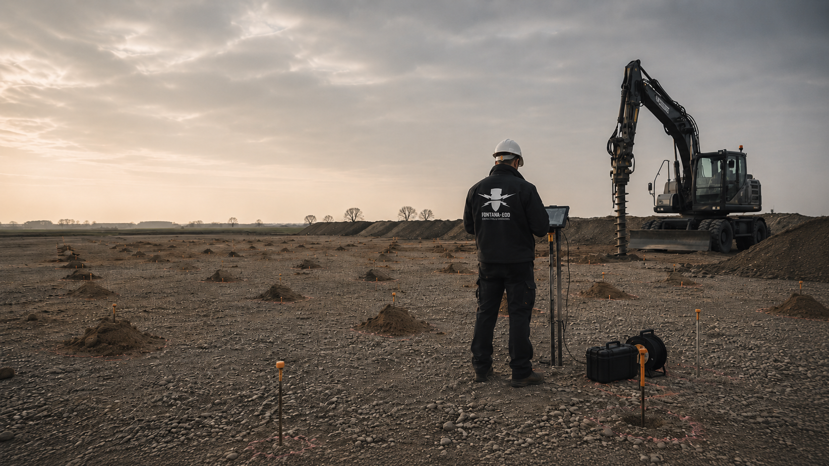
Piles, anchors, retaining-work alignments and ground accessible only after demolition are described by location, depth and construction phase. Additional investigations must suit these work volumes; an existing area-wide assessment is not automatically sufficient.
Assess depth-related investigationFor each route section, the planned groundworks are recorded in an intervention list. Carriageway, sewer reach, chamber, excavation and foundation point receive the appropriate position and depth references. The list is checked against existing evidence; areas outside the documented scope remain unresolved.
Road and civil-engineering projects combine long linear corridors with individual structures and changing construction phases. An area-wide investigation along the route does not automatically assess deep piles, retaining-work alignments or borehole positions. Carriageway, verge, drainage, junctions and structural areas are therefore considered separately.
Surfacing, utilities, reinforcement, fill, transport installations and changing ground conditions may affect measurability. The suitable method is determined by target object, surface, interference environment and required depth; a traceable follow-up measure is defined for restricted areas.
The evidence connects the route or construction area, chainage, construction section, intervention depth, method, technical limits and specialist conclusion. The statement can therefore be used in the bill of quantities, site management and project file, and updated specifically when plans change. For projects lasting several years, shared section plans show which investigations are completed or outstanding for subsections, traffic phases and structural areas. They identify the areas and depths dealt with, remaining restrictions and the additional investigation required before changed construction work.
Before work begins, investigation areas, suitable methods and required evidence are defined. Site management must be able to identify the areas and depths actually dealt with from the documents.
FONTANA-EOD starts with the specific ground intervention and the decision needed for the next project stage. A road corridor is not assessed uniformly when excavations, piles, sewers and open areas pose different tasks.
Before work starts, suspected contamination, target object, surface, ground, utilities, intervention depth, access, construction phase and regional interfaces are checked. This produces a structured service plan.
During execution, deviations, restricted areas and plan changes are recorded continuously. The conclusion remains tied to the area actually dealt with.
The project file distinguishes measurement observations, specialist assessment, actual findings and follow-up measures. This keeps communication between client, designers and site management reliable.
Route, area, depth, structure, target object and required conclusion are defined before work begins.
Methods are applied according to technical suitability, not by a fixed formula.
Measurement areas, borehole positions, excavation areas and findings retain their spatial assignment.
Utilities, interference fields and inaccessible zones are identified visibly.
Plan changes, partial handovers and outstanding measures are updated consistently.
The report answers the specific project question and identifies further measures required.
Construction responsibility, private specialist services and public hazard response interact but perform different tasks. Before work begins, it is defined who commissions investigations, reports plan changes and passes results to site management.
Define the construction task, investigation area, required conclusion and timing. They provide existing documents and commission the specialist services required.
Translate the project into routes, structures, borehole positions, depths and construction phases. They integrate ordnance assessment into design and the bill of quantities.
Implement work areas, traffic arrangements, excavation layers, protective measures and stop points. Changes to the construction sequence are communicated before the relevant intervention.
Assesses documents and suspicion indicators, develops the agreed approach, performs specialist services within the commissioned scope and documents results and limits.
Directs the relevant work within their appointment and competence and makes the safety-related decisions needed for the work sequence.
In Germany, the ordnance disposal services of the federal states and the locally competent authorities carry out hazard-response and find-management duties. Their involvement is established for the project location; outside Germany, local responsibilities apply.
Public-order and building-control authorities may be involved depending on the local procedure and construction task. Requirements and contacts are assigned to the actual road section and plan revision. Technical investigation, traffic orders and official decisions on finds are documented with their respective responsibilities.
Requirements depend on the activity, project location, find situation and responsibilities. The service specification, qualifications, risk assessment, traffic and work arrangements and documentation are tied to the specific commission.
In Germany, § 7 SprengG concerns the commercial authorisation for activities requiring authorisation; § 20 SprengG concerns the certificate of competence of responsible persons. Under § 1b SprengG, searching for found munitions also counts as handling them. The requirements applicable to the project depend on the activity actually commissioned.
The risk assessment brings together working methods, personnel, equipment, traffic, protective zones, instruction, escape routes and communication. DGUV Information 201-027 provides technical guidance for risk assessment and protective measures in ordnance clearance work.
The Baufachliche Richtlinien Kampfmittelräumung contain requirements for investigation, clearance planning, procurement, quality and documentation within their defined remit for the German federal government. Their application to the specific road or civil-engineering project is established separately.
If a suspicious object is found, stop work in the affected area immediately. Do not touch or move the object, leave the danger area and keep others away without putting yourself at risk. In Germany, notify the police immediately on 110; outside Germany, use the local emergency reporting procedure. Then inform site management.
The First Ordinance to the Explosives Act (1. SprengV) includes requirements for specialist knowledge and state-recognised training courses. Qualifications and commissioned activities are defined together for each work volume within the road and civil-engineering project.
DGUV Rule 113-003 concerns the dismantling or destruction of explosives or corresponding objects and also includes the disposal of found munitions. It applies according to this field of activity; it does not replace a risk assessment specific to the planned ground intervention.
Area and depth references, methods, qualifications, interfaces and contractual evidence are defined unambiguously.
Working methods, traffic, personnel, equipment, protective zones, instruction and communication are planned for the project.
Companies, responsible persons, appointments and specific tasks must match the scope of services.
The area worked, methods, findings, quality checks, limitations and conclusions are brought together transparently.
Service specification, geometry, qualification requirements, working methods and contractual evidence are defined.
All parties must know the responsible persons, instruction channels, traffic arrangements, stop points and changes.
Work stops immediately. Do not touch or move the object, leave the danger area and keep others away without putting yourself at risk. In Germany, notify the police immediately on 110; outside Germany, use the local emergency reporting procedure.
Reports and section plans are handed over with the applicable plan revision. They identify the areas and depths dealt with, restrictions and unresolved residual areas. When plans are revised later, it is checked whether the documented statement still covers the new intervention. Documents are checked for completeness and currency before handover to the next trade.
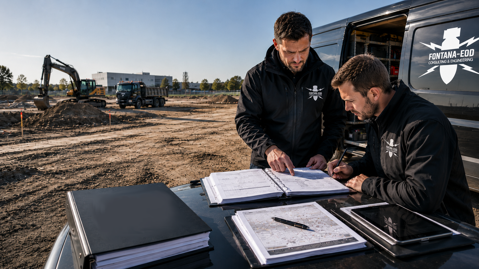
Shows the alignment, chainage, working width, crossings, structures and timing of sections.
It provides the shared spatial basis for design, fieldwork and handover.
The plan supports coordination between road design, utility construction, geotechnics and specialist ordnance planning.
Document the route and construction sections
Combines historical indicators, known finds, data gaps and prioritised investigation areas.
Technical investigation can thus be targeted at the planned intervention.
The priority map enables staged investigation without prematurely assessing later construction sections.
Assess the basis for suspicion and data gapsCombines measurement areas, lines, interference zones, anomalies and areas that cannot be interpreted.
Each anomaly receives a unique location reference and processing status.
The anomaly plan remains the shared location reference during exposure and clearance.
Assess measurement methods and anomaliesDocuments coordinates, target and investigation depths, geometry, measurement conditions and conclusions.
Plan changes can be updated for each specific point.
Point data can be checked against structural and specialist foundation design.
Investigate deep points and foundations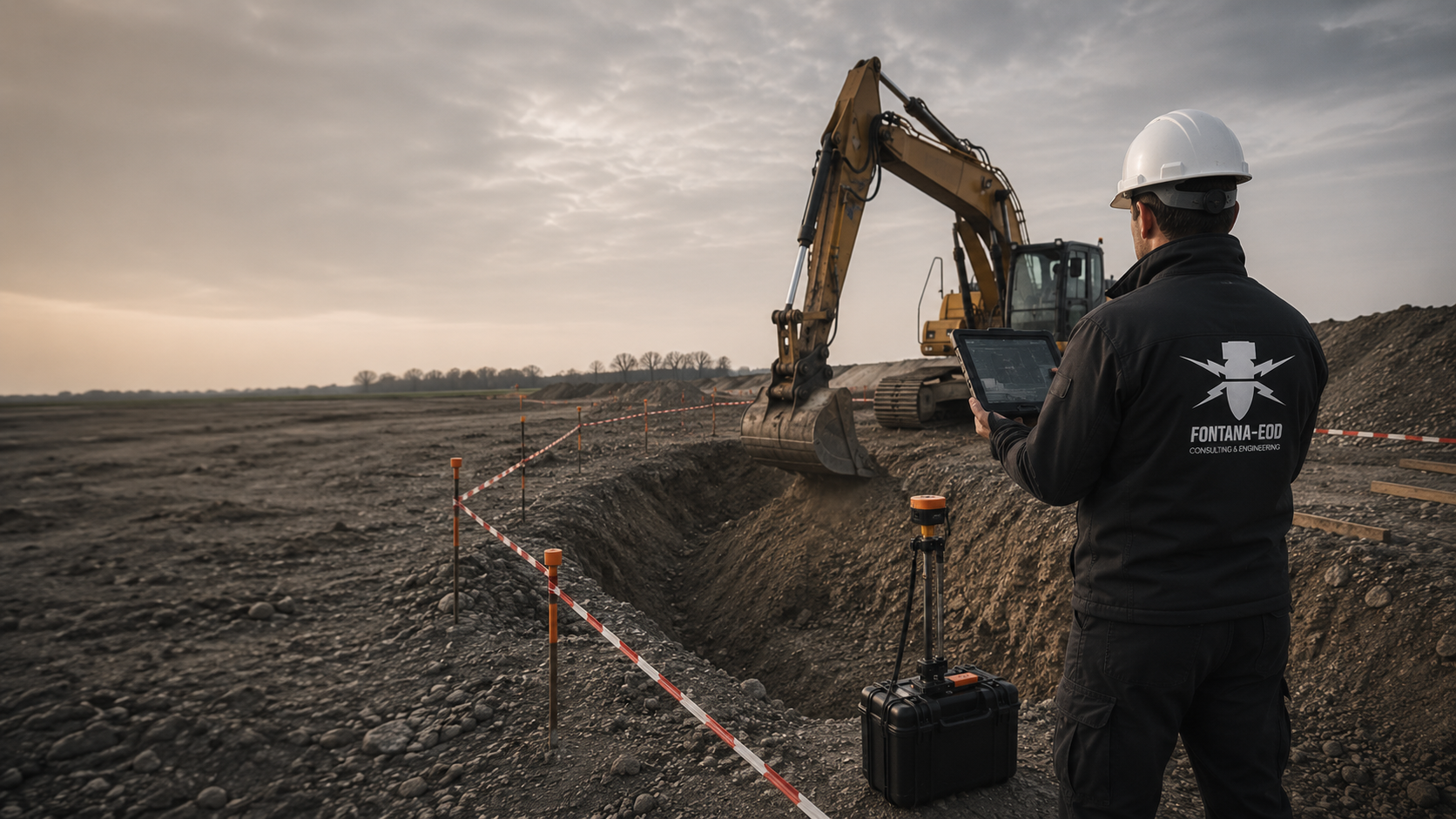
Excavation records document the section, layer investigated, soil removal, checks, interruptions, findings and follow-up measures. After actual exposure or clearance work, the corresponding findings and clearance records are added to the project file.
The statement remains limited to the work volume actually supervised.
The record shows which excavation layers were actually supervised and which areas were not dealt with.
Arrange specialist supervision of excavation layersConnects the initial situation, services, area dealt with, data, findings and specialist conclusion.
Partial reports are brought together into a consistent project status.
The complete file shows progress across construction phases, lots and plan changes.
Combine section reports into the complete file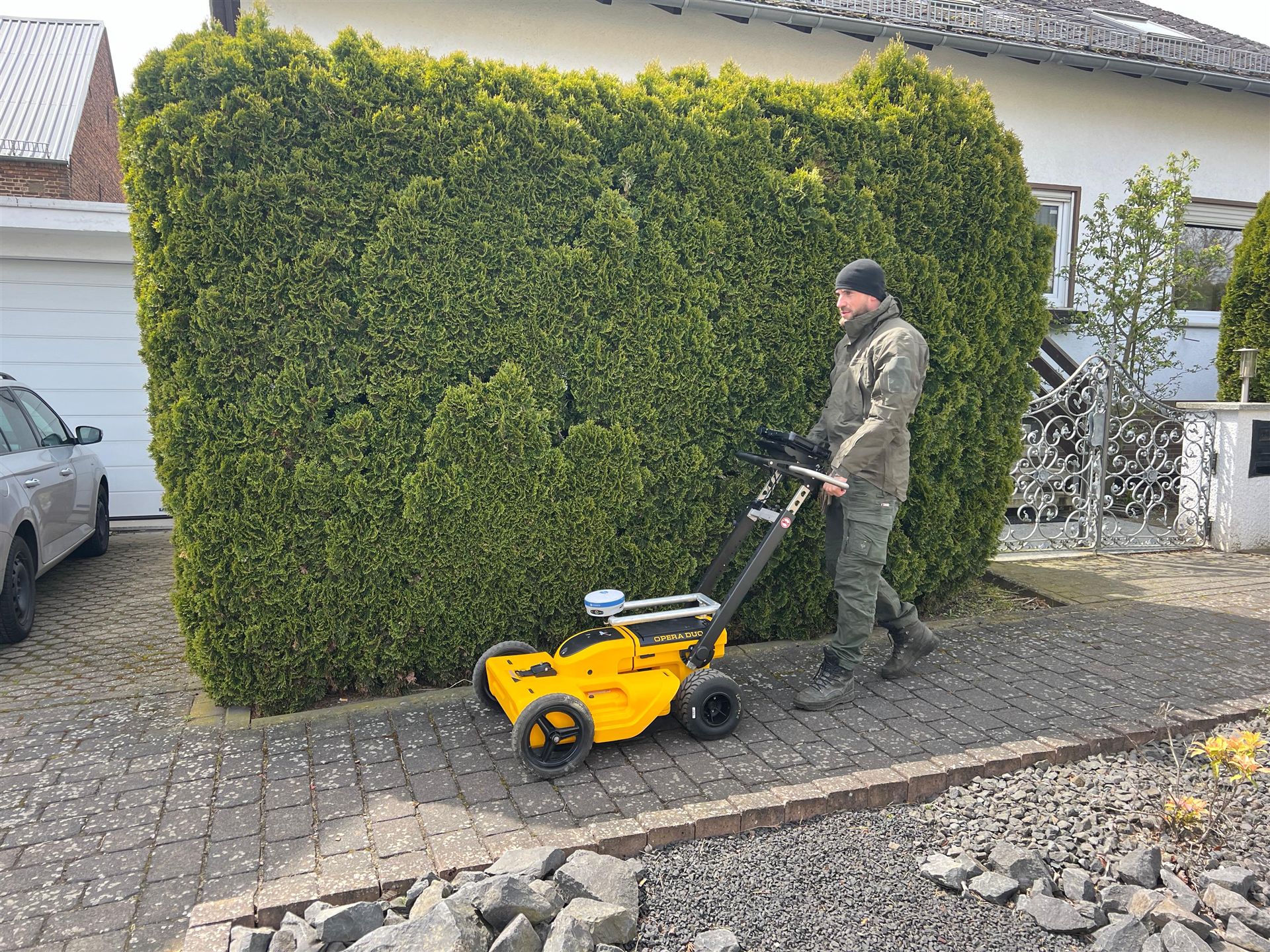
Analyse historical sources for the route and structures.
Assess the historical context of the suspected corridor
Investigate accessible road, verge and construction areas using suitable geophysics.
Plan surface assessment for civil engineering
Prepare pile, retaining-work, borehole and anchor areas with their own depth geometry.
Investigate the depth volumes of structures
Assess whether construction-phase ordnance surveying is suitable for the remaining excavation areas.
Agree construction-phase supervision of earthworks
Systematically process a defined ground volume according to the clearance objective, working depth and quality requirements.
Define the clearance objective and scope of work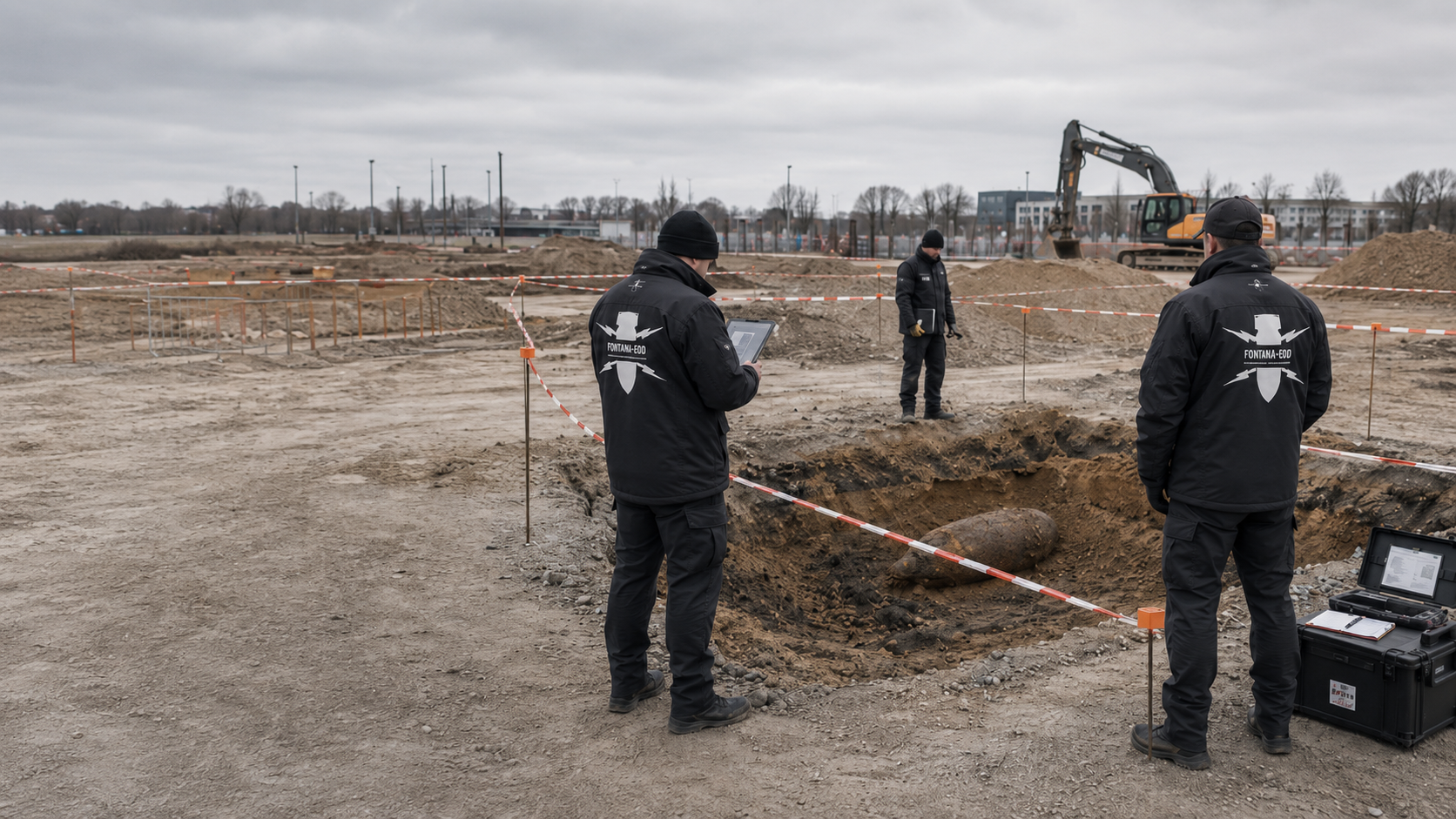
Coordinate recovery of confirmed ordnance with the permitted activities and local responsibilities.
Organise recovery and handover
Bring together procurement, quality requirements, data handover and the final report.
Prepare the project file and acceptance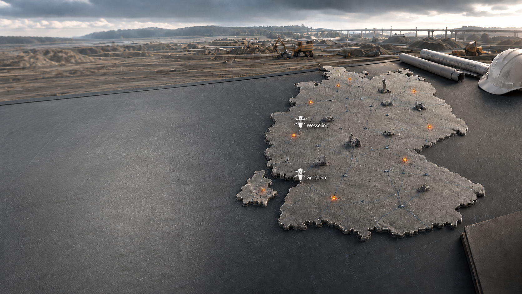
Clarify the project location, local procedures and interfaces for finds early.
Check responsibilities at the project locationState the project location and chainage of the works. Attach a plan showing the carriageway, verges, utilities, structures and temporary areas. The regional assignment supports coordination of existing requirements; the investigation scope is determined by the actual interventions and results already available.
A report provides information only for the work volume it describes. Check the plan revision, height reference and intervention depths before using it for a changed construction method or additional areas.
Understand the investigation scopeOrdnance assessment, geotechnical investigation and utility design answer different questions. Results from one discipline should therefore not replace missing documents from another.
Identify services and responsibilitiesTechnical information
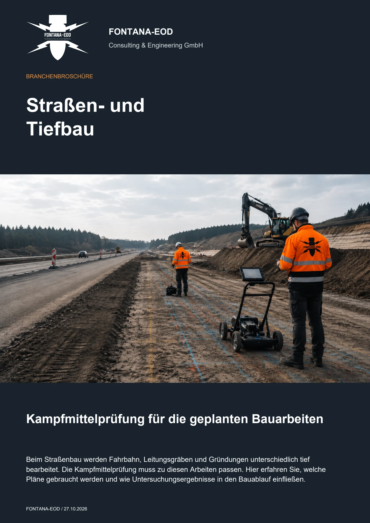
How can carriageways, bridges and deep excavations be investigated for ordnance? The brochure explains preparation, suitable survey methods and supervision of earthworks.
Assessment should begin as soon as the route, construction sections and intended ground interventions can be identified. For new roads, widening, sewers, bridges, retaining walls, underpasses, service areas and deep foundations, historical suspicion indicators, existing utilities, intervention depths and construction phases must be brought together before tendering and execution.
The carriageway, verge, central reserve, slope, drainage, sewer alignment, junction, bridge, retaining wall, noise barrier and structural foundations occupy different horizontal and vertical volumes. A near-surface route survey therefore does not automatically assess deep pile, retaining-work or borehole positions. Each work volume receives its own investigation geometry.
Selection depends on the suspected contamination, target object, surface, ground, utilities, interference environment and depth. Historical aerial-photo analysis assesses indicators of ordnance contamination; GPR, magnetometry or TDEM can investigate suitable areas. For piles, sheet-pile walls, anchors and boreholes, the suitability of point- or line-based deep-ground surveying is assessed. For areas that cannot be measured sufficiently, additional methods and possible deployment timing are established. Where construction-phase ordnance surveying is suitable, each layer is technically surveyed and assessed by specialists. Controlled layer-by-layer removal and supplementary visual inspection follow; these steps are repeated down to the agreed excavation bottom. Merely watching the excavator remove soil is not sufficient.
Existing utilities and planned services are recorded with their positions, depths and protective distances. Retaining-work alignments, pile rows, borehole positions and geotechnical investigation points receive their own coordinates and target depths. This makes it possible to assess whether an area survey is sufficient or whether deep point and linear volumes need separate surveying.
Construction phases, traffic openings, closure periods, working widths and temporary lanes must match the areas dealt with for ordnance assessment. Opening to traffic does not replace technical evidence; conversely, evidence applies only to the documented area and depth. Partial handovers are therefore recorded with the plan revision and section boundaries.
Useful documents include site and route plans, chainages, construction sections, cross-sections, utility and existing-asset plans, lists of borehole and pile positions, retaining-work alignments, intervention depths, historical analyses, letters from authorities, earlier survey reports and the required evidence. Preliminary designs can also be reviewed if assumptions and the plan revision are clearly identified.
Information and requirements from authorities are supplied with their date, complete appendices and geographical scope. In Germany, the competent ordnance disposal service, local public-order authority and, where relevant, building-control authority are established for the project location. Outside Germany, the locally competent bodies are identified through coordination.
These areas are not assessed as free of anomalies. The report states the location, depth and reason for the restriction and assigns a suitable follow-up measure. Necessary investigations and protective measures are defined before ground interventions during demolition. Depending on the intervention and measurement conditions, additional investigation of areas that become accessible later, deep-ground surveys or technically suitable construction-phase ordnance surveying may be appropriate.
If an unexpected suspicious object is found, stop work. Do not touch, move or uncover it further. Leave the immediate area and warn others without putting yourself at risk. In Germany, notify the police on 110; outside Germany, use the local emergency reporting procedure. The competent authorities determine what happens next; a project enquiry does not replace reporting the find.
The determining factors are route length, area, number of construction sections, intervention depths, utilities and interference environment, surface condition, required methods, number of deep points, access, traffic management, surveying, data volume and documentation purpose. A reliable calculation therefore requires a structured description of quantities and interventions.
An enquiry does not need a finished specification. It should, however, identify where the work will take place, the proposed ground intervention, available records and the decision required.
The project address, site plan, land parcels, route, chainage, construction-area boundaries, crossings and accessible work areas enable spatial assignment.
For several sections, the timing priorities should be identifiable.
Describe excavation, sewer, utility, borehole, pile, sheet-pile wall, anchor, demolition or other intervention with its target depth and construction method.
Traffic phases, construction schedules and parallel trades affect the method.
Aerial-photo analyses, correspondence with authorities, geotechnical documents, utility and existing-asset plans, earlier survey reports and point lists should be attached.
State whether the result is needed for design, tendering, site management or the project file.
A site plan, brief intervention description, maximum depth, planned period and available suspicion indicators are often sufficient for an initial review.
FONTANA-EOD then identifies the documents still required and the appropriate service area. Large projects can be divided by construction section, priority and decision date. Coordinate system, data formats, report recipients and required handover dates are also agreed for further planning.
Boundaries, length, width, chainage, access and construction sections.
Point list, coordinates, target depth, diameter, retaining works and construction method.
Start date, traffic phases, excavation layers, equipment deployment and parallel trades.
Documents for design, procurement, clients, site management or regional coordination.
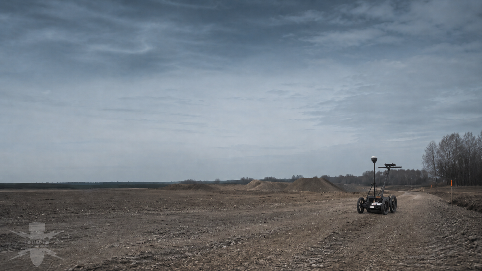
Whether historical aerial photograph analysis, explosive ordnance surveying, surface surveying using GPR, magnetometry or TDEM, deep-ground surveys, downhole surveys, excavation supervision, area clearance or ordnance recovery is needed depends on the location, ground disturbance, depth, ground and existing documents. An early ordnance assessment provides clarity for tendering, programming, occupational safety and construction.
FONTANA-EOD combines its Section 7 SprengG licence, specialists holding Section 20 SprengG certificates of competence, suitable survey and clearance methods, and traceable documentation. Send the site plan, depth of ground disturbance, construction phase and existing documents for an initial technical assessment.


