Project pathway
The quickest route to the right decision.
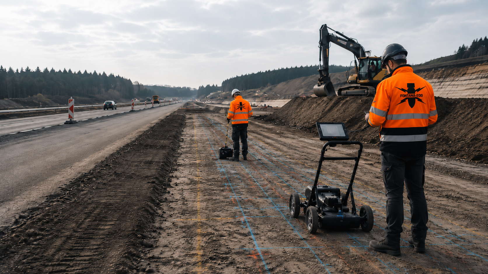
Before sewer construction, utility trenches, shafts and drainage structures are checked against the existing explosive ordnance documents. FONTANA-EOD compares documents relating to suspected ordnance with the route and intervention depths. Provide the site plan, invert levels and construction sections so that investigations and documentation for trenches, shafts and separate deep points can be agreed.
Separate trenches, shafts and structures.
Assign invert levels and shoring.
Coordinate construction phases and documentation.
In sewer construction, explosive ordnance investigation relates to utility trenches, shafts and drainage structures with their respective depths. Existing documents relating to suspected ordnance, old utilities and accessible survey areas determine further investigation requirements. Before excavation, suitable methods, outstanding subareas and section-specific documentation are agreed.
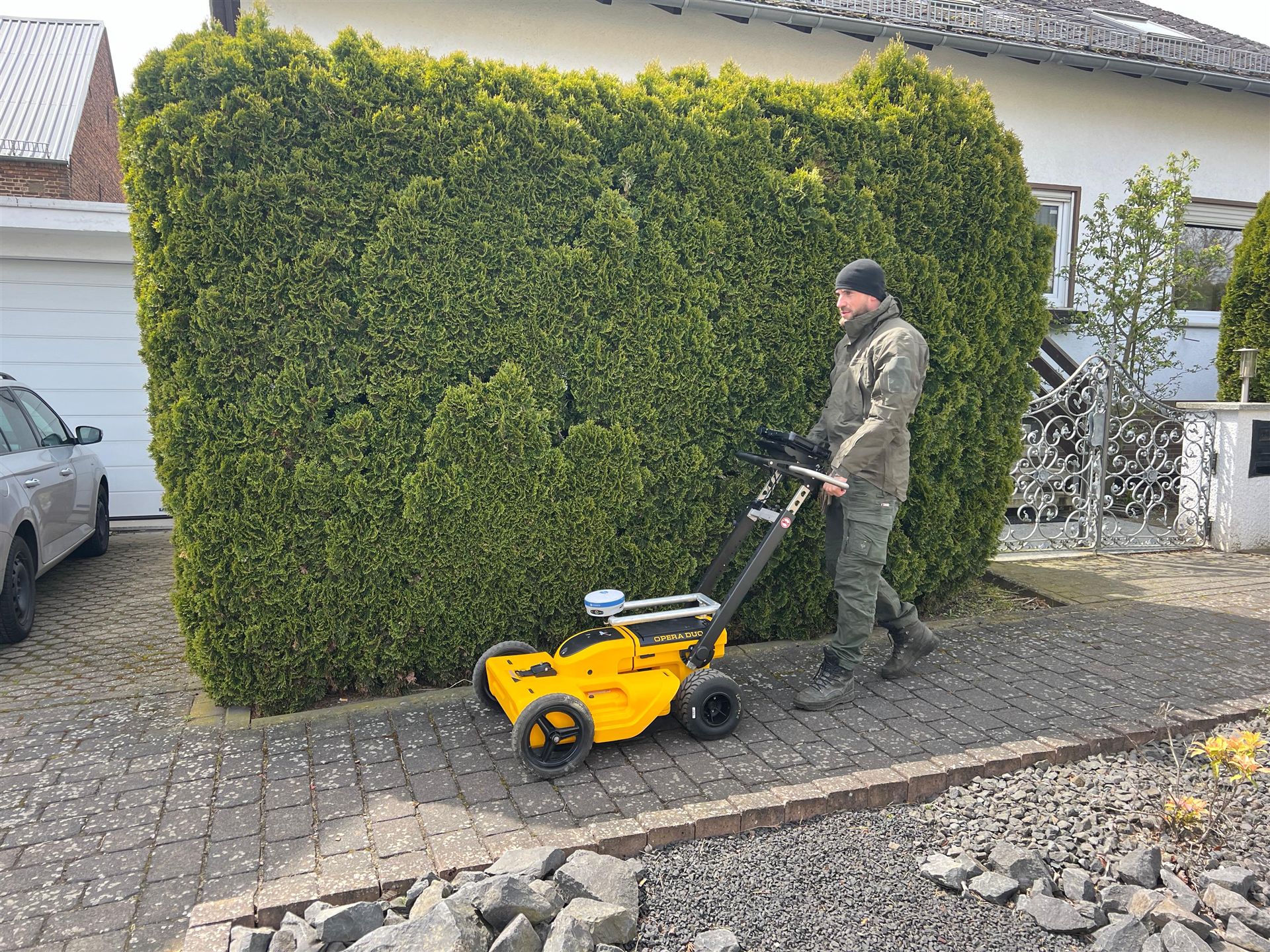
The scope of services for ‘Biebelried–Fürth/ Erlangen – A3, six-lane widening with bridge and drainage works Biebelried – Fürth/Erlangen / Deutschland’ included surface radar.
Service period: 2026-06
Service areas:Surface surveys: GPR, TDEM and magnetometryMethod used in this project: Ground-penetrating radar
View project details · GPR and limitations · Project location: Erlangen
The scope of services for ‘Lohne/Dinklage–Bramsche – A1, six-lane widening with bridges and drainage facilities Lohne – Dinklage – Bramsche / Deutschland’ included surface radar.
Service period: 2024-12
Service areas:Surface surveys: GPR, TDEM and magnetometryMethod used in this project: Ground-penetrating radar
The scope of services for ‘Sewer construction Köln -Mülheim Nordrhein-Westfalen’ included ordnance specialist supervision of groundworks.
Service period: –
Service areas:Ordnance specialist supervision of groundworks
Sewer and drainage projects consist of linear trenches, deep shafts and larger special structures. Specialist investigation follows this geometry and the actual sequence of construction phases.
Specialist planning distinguishes the pipe corridor, the working widths required for installation and the larger excavations at shafts or special structures.
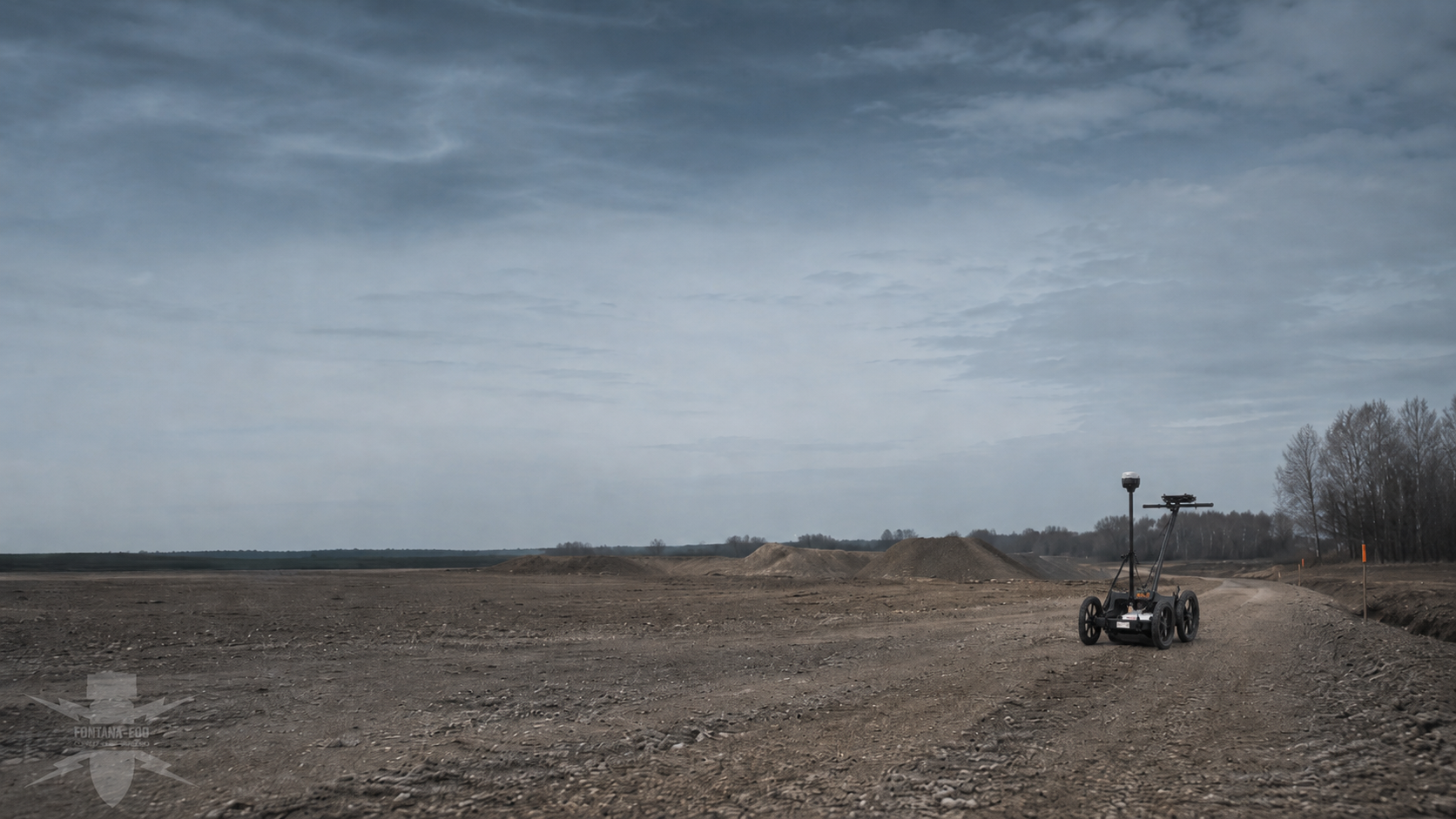
Open trenches combine linear working widths with varying invert levels, crossings and construction sections. Investigation relates to chainage, trench width and subsequent excavation depth.
Existing utilities, the road structure and backfilled areas are documented as separate survey and interference conditions.
Widenings at connections or crossings are recorded as their own geometry, rather than hidden within an average trench width.
Have the sewer route investigated by a specialist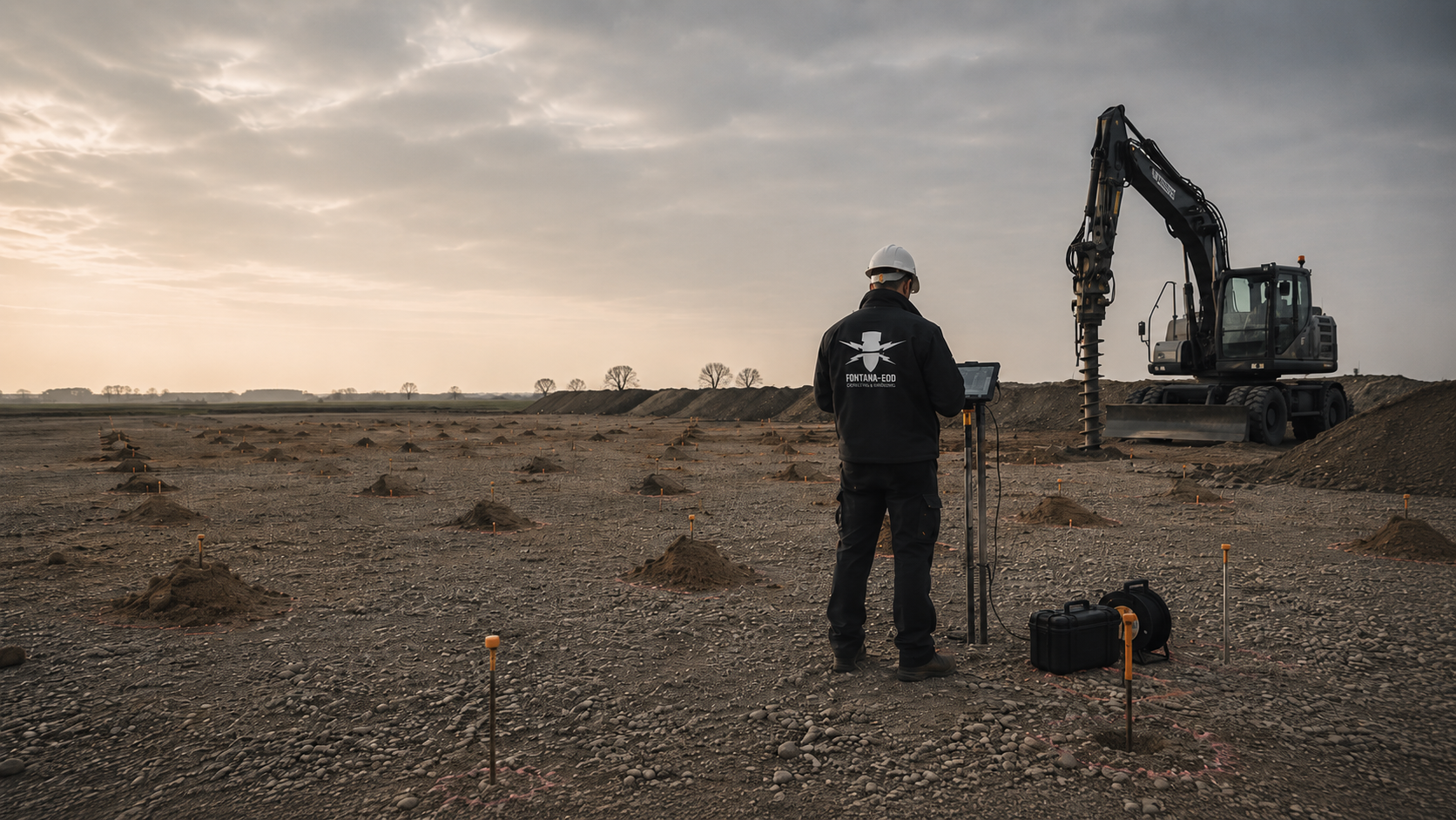
Shafts require localised, often deep excavations with shoring and dewatering. Shaft dimensions, base elevation, embedment depth and planned excavation method determine the investigation geometry.
The linear route investigation is therefore supplemented by a separate shaft status.
Shaft status remains independent of the adjoining utility section because the excavation and base elevation may differ.
Investigate shaft and depth volumesBasins, storage sewers and storage structures involve larger excavations, slopes and, where applicable, deep foundations.
Area-wide preliminary investigation, excavation bases and localised deep interventions are planned separately and recorded in a common project file.
For larger basins, slopes, base areas and possible deep foundations are treated as separate ground volumes of the works.
Assess the basin and storage structurePumping stations combine deep excavations, utility connections, electrical systems and technical installations. Existing foundations and reinforcement may limit prior surveys.
Necessary investigations and protective measures are defined for groundworks during demolition as well. Newly accessible areas subsequently receive their own investigation time.
Technical equipment and demolition stage determine when pumping station areas are accessible and can be surveyed reliably.
Investigate the pumping station and foundationCulverts, outfalls and watercourse crossings are often located on slopes, in fill or in areas affected by water. Access and survey conditions may change during construction.
Launch, reception and excavation areas are assessed separately from the crossing corridor itself.
Water level and slope access affect which areas can be investigated and when.
Have the crossing area assessed by a specialist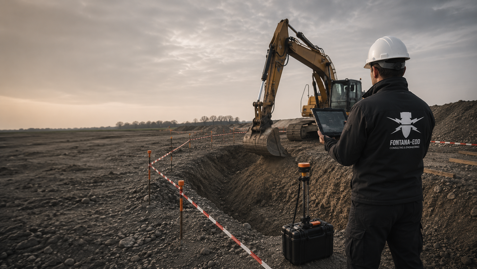
Sewer renewal, rehabilitation and reconnection usually take place in densely occupied road corridors. Old sewers, shafts, utilities and traffic areas create substantial technical interference.
Investigation requirements are defined according to the actual new groundworks, construction method and ground volume already disturbed.
For projects involving existing infrastructure, work within an already opened utility volume is distinguished from the first intervention into lateral or deeper areas.
Coordinate the existing section and excavationInvestigation requirements change from route selection to ongoing excavation. Reliable planning links the plan revision, intervention depth, existing utilities and required documentation.
In existing networks, the actual utility route may differ from the plans. This uncertainty affects equipment routes and the interpretation of geophysical anomalies.
The historically suspected hazard, existing utilities, possible routes and construction methods are compared at an early stage.
This identifies corridors requiring additional investigation, special access or a different construction method.
Options are also compared by the number of technically inaccessible remaining areas they create.
Check the historical basisThe route alignment, invert levels, shaft locations, excavations and shoring are related to the suspected area.
Unresolved geometries and design assumptions remain identified so that later changes can be assessed by a specialist.
Shaft and invert-level plans are updated as soon as surveying or ground investigation provides new elevation information.
Assess the design revision with specialist inputThe scope of services, chainage, depths, construction sections, traffic phases, qualifications and required documentation are clearly described.
Provisional items receive a clear trigger, such as additional shafts or areas accessible only after demolition.
Service items receive clear chainage and structure references for quantity measurement and acceptance.
Structure the tender documentsBefore shaft, sheet-pile or drilling works, the ground volume of the subsequent works must be described with coordinates and target depth.
An area survey of the route does not replace point-specific or line-specific depth investigation.
Before installation, the shaft setting-out on site is checked against the approved plan revision.
Prepare deep shaft areasWhere existing utilities or the surface structure limit prior surveying, the suitability of an explosive ordnance survey alongside construction for the planned intervention is assessed. Each working layer is surveyed using technical equipment and assessed by a specialist before removal.
Excavation layers, hold points and communication routes are defined before work begins.
Controlled removal in layers and supplementary visual inspection follow technical investigation and assessment. These steps are repeated down to the agreed excavation base; simply watching excavation is insufficient.
Coordinate the excavation sequence with specialist inputSurvey anomalies, technical installations and actual finds are distinguished by a specialist.
Location, condition, working surroundings and regional responsibilities determine further investigation.
If a suspicious object is encountered, work in the affected area stops immediately. The object is left unchanged and people leave the immediate area. The responsible authorities are notified through the local emergency reporting route. Further investigation and resumption of work follow their decision.
Clarify the findings and handover processSewer projects require section-specific statements for trenches, shafts and special structures.
Investigation status is therefore recorded along the chainage and through clear structure identifiers. This facilitates section-by-section tendering and handover.
Initial situation: the planned sewer alignment lies in an area whose assessment is not complete.
Next step: historical sources are related to the route, shafts and special structures.
Documentation: suspected sections, data gaps and recommendations for technical investigations.
The historical assessment prioritises route sections and special structures according to their specific intervention depth.
Initial situation: a road or open-area section can be surveyed and is intended for open-cut excavation.
Next step: select a suitable surface method according to target object, surface and interference conditions.
Documentation: survey area, anomalies, limitations and follow-up decision.
Surveyability is verified on site because the road structure and utility density may change over short distances.
Initial situation: a localised excavation or foundation volume extends considerably deeper than the route survey.
Next step: coordinate deep-ground or borehole surveying with shaft geometry, shoring and target depth.
Documentation: point or alignment status with depths reached and outstanding measures.
Shaft investigation also includes shoring and lateral working space, rather than only the centre of the structure.
Initial situation: utilities, old sewers, shaft structures and traffic areas obscure the survey.
Next step: distinguish subareas whose data can be evaluated from technically limited zones.
Documentation: spatially identified limitations and planned supplementary investigation.
The supplementary investigation is defined with its construction stage, ground volume and investigation time.
Initial situation: the relevant ground becomes accessible only after road excavation or utility exposure.
Next step: define necessary investigations and protective measures before groundworks during road excavation. Organise investigation and earthworks by section and layer for the areas accessible afterwards.
Documentation: excavation layers investigated, interruptions and the next release decision.
Handover of the exposed excavation base is documented with chainage, date and construction boundaries.
Initial situation: surveying or excavation reveals an anomalous location.
Next step: investigate the finding further within the agreed scope of services and responsibilities.
Documentation: location, investigation, handover and delineation of outstanding route sections.
A findings register prevents individual anomalies from being confused with the status of entire utility sections.
The documentation must link chainage, shaft reference, depth, method, interference zones and the follow-up decision. This keeps the investigation status usable across construction phases and plan changes.
For network operators, it is essential that a report distinguishes the technically investigated section from areas merely known or opened previously.
Site management must also be able to trace which route section has been investigated, which has only received historical assessment and which remains outstanding because of existing infrastructure, traffic or utility density. A consistent status display prevents uninvestigated zones from being included inadvertently in the next construction section.
The route alignment, chainage, shaft identifiers, construction sections and plan revision form the spatial basis.
Changes to location, gradient or shaft sequence are updated by revision.
Chainage references and section identifiers are updated traceably from design through as-built documentation. If the route location, pipe dimensions or shaft positions change, it remains clear which plan revision an investigation relates to and which new ground volumes require additional assessment.
Aerial photograph assessments, official correspondence, known finds and earlier reports are documented with their scope.
Unclear or contradictory information remains visible as specific points requiring clarification.
Discrepancies between utility information and the actual location on site are recorded in the report as a separate basis for planning.
Old sewers, utility services, shafts, structures and known installations are recorded with their positional accuracy and data revision.
Information about existing conditions supports interpretation but does not replace specialist investigation of the new ground volume.
Depth data relates to a defined height and reference system, rather than only depths below ground level.
Survey lines, borehole points, shaft geometries, depths reached, sources of interference and evaluation are recorded by section.
Areas whose data cannot be evaluated or that cannot be reached receive a clear location and follow-up measure.
Survey data and structure lists are handed over in agreed formats so that network operators can reuse them.
Excavation layers, exposed bases, hold points, observations and actual findings are assigned to the respective trench or shaft section.
Interruptions and changes to the construction sequence remain traceable.
Daily and section status are linked to the traffic phase and construction crew.
The report describes routes, shafts and depths investigated, limitations and outstanding measures.
The statement remains limited to the documented ground volume and plan revision used.
The final record explicitly identifies connection or lateral areas outside the investigation assignment.
Sewer projects generate numerous plan revisions, chainage references and changes during construction. The dossier keeps this information together on a common spatial basis.
Data from utility records, surveying and explosive ordnance investigation is assessed for origin and accuracy before being combined.
Historical information, route plans, shaft lists and revisions are recorded with clear designations.
This shows which geometry underlay each decision.
The plan register and chainage schedule prevent use of outdated route revisions.
Utility sections, shaft structures, pumping stations, basins and crossings receive consistent identifiers.
This allows investigation status, depth and follow-up measures to be assessed by section.
Shaft identifiers, chainage references and plan revisions link fieldwork and the final report. Changed identifiers are clearly related to the earlier revision so that investigation results are not transferred to relocated shafts or changed intervention depths.
Raw data, survey lines, drilling records, depth information and evaluation are organised by section and method.
The structure supports later plan revisions and specialist reviews.
Raw data, evaluation and mapped anomalies remain linked through clear file names.
Anomalies from surveying and excavation are linked to chainage, shaft identifier, investigation stage and the civil engineering decision.
Outstanding points remain clearly separate from completed measures.
Outstanding points receive a date, responsibility and expected specialist follow-up.
Road excavation, trench construction, shaft construction, crossings and reinstatement are recorded in an overview that can be updated.
This allows site management to identify the ground volume investigated at each stage.
Subsections can be handed over while clearly showing the status of adjoining areas still outstanding.
The report, plans, chainage lists, limitations and communication records are handed over in the agreed form. Where exposure or clearance work has actually taken place, the corresponding findings and clearance records are included.
Later changes to the route or shaft sequence can therefore be clearly checked against the documented section status.
The handover is structured so that later rehabilitation or connection works can also identify the earlier investigation volume.
The process is adapted to the construction method, traffic phases and shaft sequence. Each step provides a specific basis for the next civil engineering section.
Fieldwork is coordinated with the planned civil engineering crews and traffic phases so that surveying and evaluation are ready before the respective surface removal.
The route, shafts, special structures, construction method, invert levels, construction phases and required statement are described.
Historical sources, existing utilities, ground data, earlier excavations and existing reports are related to the ground volume of the works.
Linear route sections, deep shaft excavations, crossings, pumping stations and basins receive their own investigation geometries.
Area surveys, deep-ground surveying, later investigation after surface removal and measures alongside construction are planned according to access.
Chainage, survey paths, borehole points, traffic areas, equipment access, protective zones and contacts are agreed.
Surveys, depth investigations or layer-specific excavation steps are carried out in accordance with the agreed geometry.
Survey values, anomalies, exposure work and limitations are checked for plausibility against the route, shaft and subsequent intervention.
The report, plans, chainage status and outstanding measures are prepared for the network operator, planners and site management.
Sewer construction combines linear trenches, deep shafts and road corridors densely occupied by technical infrastructure. Investigation geometry must clearly reflect these differences.
Deep shafts, shoring and trenchless crossings require spatial consideration beyond the near-surface route corridor.
For an open sewer trench, the alignment, working width, trench depth, slopes or shoring and section-by-section construction sequence are required. Investigation relates to the volume actually opened later, rather than only the pipeline alignment.
Shafts, pumping stations and special structures have larger and deeper excavations. Their investigation is planned using the shaft identifier, dimensions, base elevation, shoring and any piles or anchors.
Existing utilities and old sewers may obscure surveys or obstruct equipment routes. The available data, positional accuracy and actual access are therefore checked before fieldwork.
For trenchless construction, the launch pit, reception pit, bore path and possible depth volumes are considered separately. A near-surface survey at the pits does not automatically address the entire underground corridor.
Chainage, trench width, invert level and local widening determine the area-wide investigation volume.
In addition to pipe width, the investigation volume includes working space, shoring and lateral widenings.
Shaft diameter, excavation dimensions, shoring, dewatering and target depth are recorded as a separate ground volume of the works.
Shafts are described with a height reference and excavation geometry, rather than only a surface coordinate.
Existing utilities, safety clearances and positional uncertainties affect survey paths and possible alternative methods.
Uncertain utility data leads to adapted field planning rather than a general assumption of an unobstructed survey path.
Launch and reception pits, bore path, pull-in length and depth are considered separately in method planning.
For trenchless construction, the pits and underground course are treated as different technical tasks.
Asphalt, base layers, earlier excavations and heterogeneous fill alter surveyability and data interpretation.
Heterogeneous fill may change survey responses and is checked for plausibility against ground and existing-condition information.
Surface removal, excavation, pipe laying, backfilling and surface reinstatement receive clear handover points.
The section is handed over before backfilling or the next civil engineering step, with clear confirmation of its location.

Explosive ordnance investigation becomes relevant where sewer construction, drainage or utility renewal enters ground whose historical assessment is incomplete. Decisive factors are the route location, trench depth, shaft structures, shoring, dewatering and which sections are actually accessible and surveyable before construction begins.
Assess the basis for suspicionNear-surface route areas may be investigated using a suitable geophysical method. Deep shafts, pumping stations, launch and reception pits, sheet piles or localised foundations require separate depth or excavation assessment. A linear area survey does not automatically cover these ground volumes.
Existing utilities, old sewers, metal installations, the road structure and earlier excavations may substantially alter the ability to evaluate data. Areas that cannot be investigated sufficiently are shown spatially. For these areas, the technical suitability of investigation at a later construction stage, a deep-ground survey or a measure alongside construction is assessed.
Assess depth-related investigationThe methods measure different properties and have their own spatial limitations. Their combination follows the route, shaft geometry and construction method.
Methods are combined according to target object and interference conditions; a single survey system is not applied indiscriminately to the entire sewer alignment.
Establishes whether historically founded suspicion exists and in which route sections.
It does not state which objects are actually present in the utility volume today.
Historical sources structure further investigation requirements along the route.
Investigates accessible road or open areas using a suitable geophysical method.
Utilities, old sewers and shaft structures may limit data evaluation.
Area-survey methods are adapted to changing surfaces and utility densities.
Investigates deep shafts, excavations, shoring, piles or defined borehole points.
The statement remains limited to the defined point and depth geometry.
Deep structures require their own survey and setting-out planning.
Uses the new construction stage where asphalt, the road structure or installations prevented earlier surveying.
The timing is coordinated with traffic and construction phases.
Road excavation creates new access while also changing the surface and construction stage.
In a technically suitable explosive ordnance survey alongside construction, each working layer is surveyed using technical equipment and assessed. Controlled removal in layers and supplementary visual inspection follow; these steps are repeated down to the agreed excavation base. Simply watching excavation is insufficient. The ground volume, interference zones, hold points and remaining areas are documented.
Individual suspected points are professionally exposed and assessed. Recovery of confirmed explosive ordnance is coordinated with the permitted scope of activity and local responsibilities.
It does not replace investigation of the rest of the route.
The handling of a specific find remains spatially distinct from the rest of the utility project.
Magnetometry detects magnetic anomalies, particularly those caused by ferromagnetic objects. It can be used to investigate suitable unobstructed survey areas. Reinforcement, vehicles, shoring and other iron masses may obscure signals. The survey grid, interference areas and areas capable of evaluation are documented; a magnetic signal does not yet identify an object.
TDEM detects time-dependent electromagnetic responses from conductive objects. Target size, depth, survey geometry and the technical surroundings determine the achievable statement. Utilities, reinforcement and metal installations may limit evaluation. Results are checked against the basis for suspicion and further investigations; the method does not replace other methods indiscriminately.
Ground-penetrating radar records reflections of electromagnetic waves at material boundaries. The data may reveal structures, utility routes or anomalies in the ground investigated. Soil, moisture, conductive layers, reinforcement and survey geometry affect penetration and evaluation. A radar anomaly alone does not identify explosive ordnance or support a general statement for deeper interventions.
A reliable explosive ordnance investigation is based on clear chainage, justified method selection and documentation identifying each section and structure separately.
Quality assurance links chainage, field records, plan revision, raw data and the specialist assessment of each route segment.
FONTANA-EOD takes the actual groundworks as its starting point. The utility trench, shaft, pumping station and crossing are treated as technically distinct tasks, linked through the same spatial and plan reference.
Existing utilities, traffic areas and fill are considered during work preparation. Where prior surveying is limited, the next suitable investigation stage is planned.
During execution, changed routes, additional shafts and new depths are updated in the records. The conclusion remains limited to the volume actually investigated.
Results are prepared for network operators and site management so that outstanding sections, completed structures and required follow-up measures remain clearly identifiable.
The route, section, shaft, structure and plan revision are defined before work begins.
Methods depend on the target object, surface, existing utilities, depth and access.
Surveying, road excavation, trench construction and shaft construction are coordinated in time.
Survey data, drilling records, excavation layers and findings remain spatially assigned.
Areas whose data cannot be evaluated or that cannot be accessed are clearly shown.
The report assesses route status and identifies the measure still needed before the next sewer construction section.
Project documentation must show which route or shaft section was investigated and to what depth. This allows network operators, planners and site management to incorporate investigation status into construction phases, traffic management and excavation logistics.
Sewer projects combine linear routes with localised depth volumes. The utility trench may begin near the surface, while shafts, pumping stations, inverted siphons or launch and reception pits extend considerably deeper. Explosive ordnance investigation is therefore divided by section, construction method and actual ground volume occupied, rather than defined indiscriminately for the entire project.
For drainage works in urban areas, traffic, property connections, existing sewers, crossing utilities and limited equipment standing areas affect surveyability and the work sequence. Handover points defined early between surveying, utility diversion, shoring and excavation prevent formally existing documentation from being applied to a technically changed ground volume.
The route, shaft sequence and construction stage must be recorded using the same identifiers and responsibilities across planning, network operation and execution.
Defines the route section, shaft sequence, construction method, priorities and documentation needed for planning and tendering.
Provides existing-condition, sewer and suspected ordnance documents, including their known uncertainties.
Translates the project into alignment, chainage, invert levels, shafts, pumping stations, basins and crossings.
Identifies plan changes so that their impact on sections already investigated can be assessed traceably.
Compiles information about old sewers, electricity, gas, water, telecommunications and areas with unknown utilities.
Data quality and positional accuracy are disclosed so that survey limitations and safe equipment routes can be planned realistically.
Implements trench sections, shafts, shoring, dewatering and traffic phases in accordance with the agreed work sequence.
Additional widenings, depths or new shaft locations are referred back to explosive ordnance planning before execution.
Assesses the route, suspected hazard and existing surroundings, carries out the commissioned investigations and documents their coverage.
Results are prepared so that network operators and site management can clearly adopt the status of each section.
In Germany, the ordnance disposal services of the federal states and the locally competent authorities carry out hazard-response and find-management duties. Their involvement is established for the project location; outside Germany, local responsibilities apply.
The private project service and official decision remain clearly distinct technically and organisationally.
The local public order authority and building control authority may be involved depending on the procedure and construction task. Responsible contacts, conditions and reporting routes are assigned to the project location and the work sections concerned. Technical investigation, construction organisation decisions and official handling of ordnance finds retain their respective responsibilities.
Sewer construction combines deep trenches, shoring, dewatering, road traffic and densely occupied utility corridors. The explosive ordnance task is coordinated with these occupational safety and site conditions.
Network operators, site management and the specialist company need a common plan and chainage reference so that interruptions and section handovers remain clear.
In Germany, § 7 SprengG concerns the commercial authorisation for activities requiring authorisation; § 20 SprengG concerns the certificate of competence of responsible persons. Under § 1b SprengG, searching for found munitions also counts as handling them. The requirements applicable to the project depend on the activity actually commissioned and the allocation of responsibilities.
DGUV Information 201-027 supports risk assessment for explosive ordnance clearance. Trenches and shafts additionally require consideration of stability, safe access, shoring, dewatering and traffic routes.
The Baufachliche Richtlinien Kampfmittelräumung contain requirements for investigation, clearance planning, tendering and documentation within their defined federal scope. Their application to the specific sewer project is clarified separately; agreed requirements are linked to chainage, shaft identifier and construction phase.
The First Ordinance to the Explosives Act (1. SprengV) includes requirements for specialist knowledge and state-recognised training courses. For sewer and drainage works, the required qualification is related to the investigation or clearance scope actually commissioned.
DGUV Rule 113-003 concerns the dismantling or destruction of explosives or corresponding objects and also includes the disposal of found munitions. It applies according to this field of activity; it does not replace a risk assessment specific to the planned ground intervention.
Route length, working width, invert levels, shafts, construction method and documentation objective are clearly specified.
Shoring, slopes, dewatering, entry and exit, and equipment position are included in the risk assessment.
Known utilities and those with uncertain locations affect survey paths, safety clearances and possible alternative methods.
Procedures for anomalies, work stoppages, securing the area and regional involvement are organised before construction begins.
Chainage, quantities, depths, plan revisions and required section documentation are described in comparable terms.
Changes to trench width, shaft location or invert level are assessed by a specialist before the intervention.
Stop work immediately, leave the immediate area and notify the responsible authorities without delay. The responsible authorities determine the next steps.
The work results link the historical basis, route and shaft geometry, excavation status and follow-up decision in a section-specific project file.
Project documents are prepared so that site management and network operations can clearly identify status even where several sections are being worked on in parallel.
Suspected areas and outstanding data gaps are related to the sewer alignment, shafts and special structures.
Clarify the suspected hazard for the route
Coordinates, base elevation, excavation geometry and survey conditions are documented for deep shafts.
Have deep shafts investigated by a specialist
Excavation layers, exposed bases, interruptions and outstanding edges are recorded by section.
Coordinate the excavation sequence with specialist input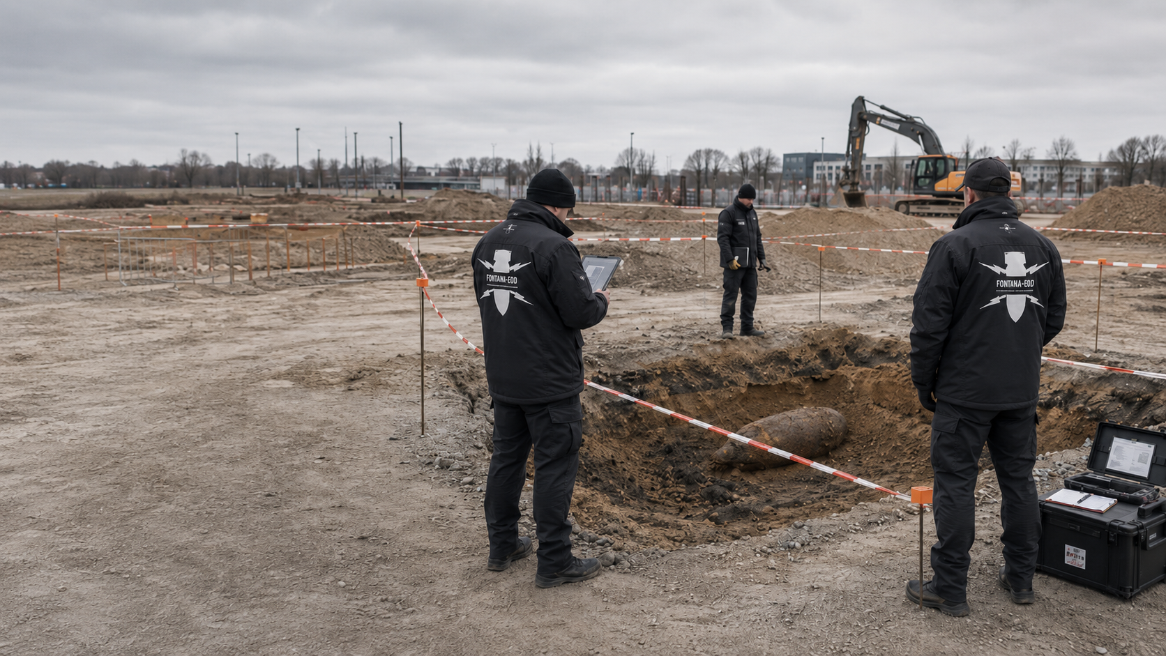
Anomalies and finds remain linked to chainage, shaft identifier and the responsibility and reporting route.
Assess the investigation of findings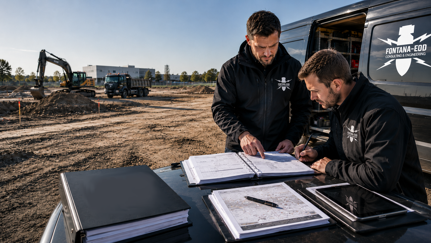
Reports, chainage lists, site plans and construction phase status are combined in a form that can be updated.
Structure the route file and section handover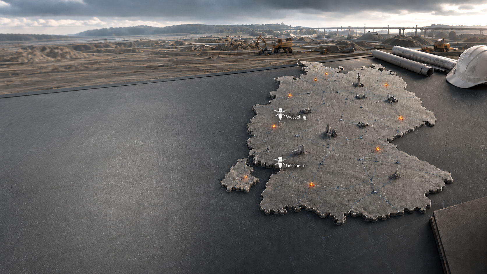
The project location determines regional procedural and find-related interfaces that feed into work preparation.
Assess the project region with specialist input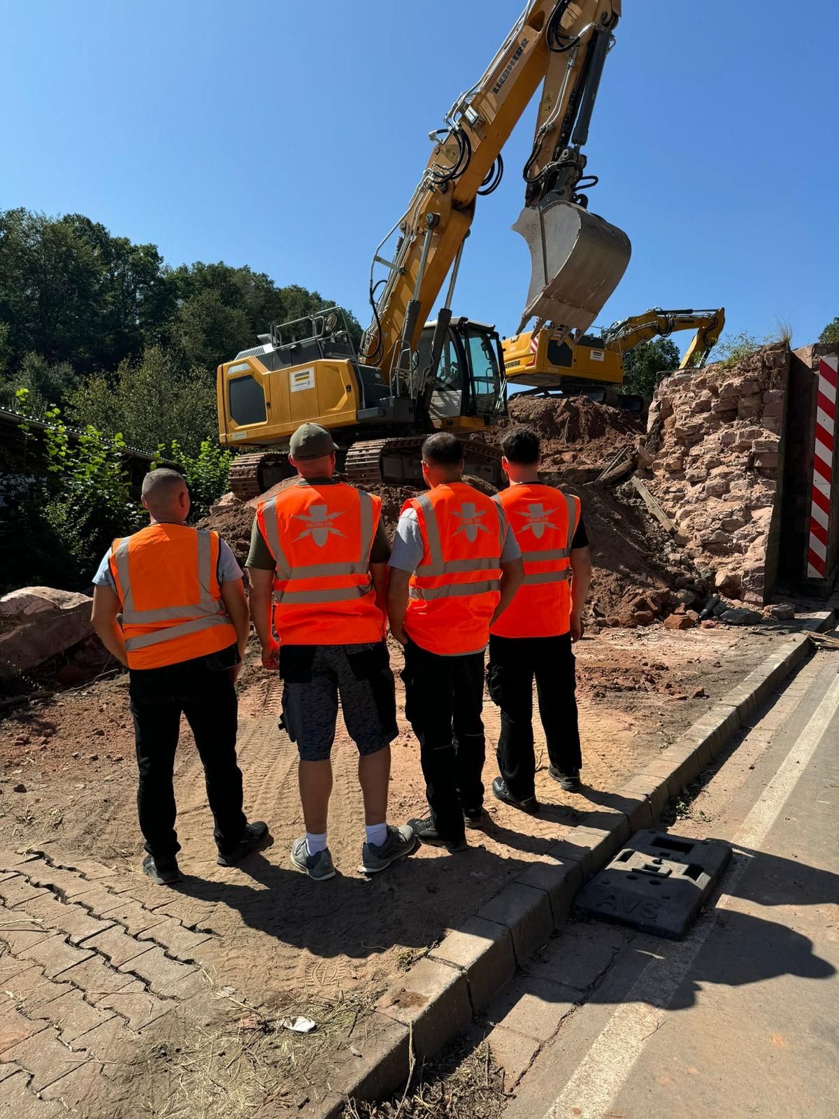
Surveys, investigations alongside construction and documentation must be coordinated with the planned trench and shaft sections.
Chainage, shaft identifier and intervention depth link the individual services to the execution design.
Place sewer construction and drainage in the wider road and civil engineering context.
Assess the sewer project in its civil engineering context
Establish the spatial basis for the suspected hazard and affected route sections before technical investigation.
Clarify historical suspicion indicators
Relate deep shafts, shoring, pumping stations and borehole points to the subsequent intervention geometry.
Have deep shaft areas investigated by a specialist
Assess the suitability of an explosive ordnance survey alongside construction for remaining trench and shaft areas.
Prepare trench and shaft excavation
Coordinate recovery of confirmed ordnance with the permitted activities and local responsibilities.
Clarify the recovery and handover process
Coordinate the service specification, chainage reference, quality control and final documentation.
Prepare the specification and chainage documentation
Assess the project location, federal state and regional interfaces for finds and procedural matters.
Check regional responsibilities
Have the route plan, shaft list, depths, construction phases and existing documents relating to suspected ordnance reviewed by a specialist.
Enquire about the sewer project with supporting documentsProvide the project location, route alignment and chainage together with the shaft list. Excavations additionally require dimensions and base elevations. Link this information to the current utility and construction phase plan so that results are not extended to a neighbouring or deeper ground volume.
A depth requires a clear height reference. If the excavation base, shoring or dewatering changes, check whether the ground volumes occupied are included in the existing report.
Check depth and area referencesUtility plans and information about existing installations are additionally required. Explosive ordnance investigation does not replace utility locating or coordination with the network operator; existing infrastructure also affects survey conditions and safe work planning.
Distinguish service limitationsTechnical information
How can carriageways, bridges and deep excavations be investigated for ordnance? The brochure explains preparation, suitable survey methods and supervision of earthworks.

Investigation should begin once the route, shaft locations, construction method, trench depth and construction sections are sufficiently identifiable. For new construction, renewal, stormwater retention basins, pumping stations, culverts or open utility trenches, the suspected hazard, existing utilities, dewatering and accessible investigation volumes must be brought together before tendering.
The utility trench, shaft excavations, property connections, pumping stations, retention basins, culverts, launch and reception pits and site establishment areas differ in area, depth and access. An area survey of the route corridor does not automatically address deep shafts or bore paths. Each ground volume therefore receives its own location and depth reference.
Shafts and pumping stations often require deep excavations, shoring, dewatering and localised foundations. Investigation must cover the excavation geometry, shoring alignments, base elevation and any piles or anchors. Near-surface surveys are sufficient only if the entire ground volume of the subsequent works can be technically covered and assessed by a specialist.
Where possible, provide site and route plans with chainage, pipe dimensions, invert levels, shaft lists, excavation and shoring details, open-cut or trenchless construction method, construction sections, existing utilities, dewatering, historical assessments and existing survey reports. Incomplete existing-condition plans are also relevant if their uncertainty is identified.
Include existing information and conditions from authorities with their dates, complete attachments and spatial scope. In Germany, the responsible explosive ordnance disposal service, local public order authority and, where applicable, building control authority are identified for the project location. Outside Germany, coordination takes place with the authorities responsible there. Outstanding questions are assigned to the actual construction section.
The work is linked to the section sequence, traffic management, dewatering, material logistics and access. Areas that can be surveyed are brought forward where possible. Necessary investigations and protective measures are defined before groundworks during demolition or surface removal. Areas accessible only afterwards receive their own investigation date. Where an explosive ordnance survey alongside construction is technically suitable, technical investigation and assessment of each working layer are scheduled before controlled removal. Supplementary visual inspection, excavation layers, hold points and documentation are agreed before work begins; the sequence is repeated down to the agreed excavation base.
The documentation links the route, chainage, shaft or structure identifier, plan revision, method, depth reached, interference zones, anomalies, outstanding areas and follow-up decision. This makes it possible to trace which utility or shaft section was investigated and which measures are still needed before the next civil engineering step.
Decisive factors are route length, working width, trench depth, number and depth of shafts, traffic phases, utility density, surface, construction method, dewatering, necessary depth investigations, inaccessible areas and documentation scope. A reliable cost calculation therefore requires clear plan revisions, chainage and construction section priorities.
An initial enquiry does not yet need to contain a complete specification. However, it should identify the route section, shaft geometry, intended depths and construction method.
In addition to length and depth, state traffic management, dewatering and the date by which the specialist statement is needed for each section.
Provide the site plan, route alignment, chainage, construction sections, pipe dimensions and current plan revision.
Shaft locations, crossings, special structures and inaccessible areas should be clearly marked.
Include shaft lists, invert levels, excavation dimensions, shoring, dewatering and the open-cut or trenchless construction method.
Bore paths, launch and reception pits and particular traffic phases affect the methodology.
Utility and existing-condition plans, historical assessments, correspondence with authorities, ground data and earlier survey reports are useful.
State when the statement is needed for planning, tendering, network operation or site management.
A site plan, brief route description, shaft list, maximum depth, construction phases, planned period and existing indications of suspected ordnance are often sufficient for an initial review.
FONTANA-EOD then identifies the documents still needed and the appropriate scope of services for trenches, shafts and special structures.
Alignment, chainage, working width, construction sections and crossings.
Shafts, pumping stations, shoring, base elevations and excavation depth.
Traffic management, dewatering, open-cut or trenchless construction and time windows.
Basis for planning, tendering, the network operator, site management or the project file.
For long sewer routes, also identify which sections will be tendered first, built under traffic or accessible only after utility diversion.
For open-cut construction, trench width, slopes or shoring and the intended layer sequence are required. For trenchless construction, the launch pit, reception pit, bore path, diameter and planned depth must be specified separately.
Network operators benefit from a data structure agreed early: chainage reference, shaft identifier, coordinate system, plan revision and status designation should match across survey data, daily reports and as-built documentation.
Existing utility information does not replace checking its positional accuracy. Utilities with uncertain positions or shown only schematically are considered as a separate constraint for equipment routes, safety clearances and interpretation.
For stormwater retention basins and pumping stations, excavation dimensions, slope angle, dewatering, possible deep foundations and temporary access routes are also relevant. These areas may lie outside the sewer alignment itself.
Investigation by section allows route areas needed early to be brought forward without mixing their status with later construction sections. Every partial handover is retained in the overall file and clearly delineated spatially.
The final enquiry should also state expected daily output, available intermediate working areas and the sequence of shaft structures. These details affect how surveying, exposure work and section-by-section handover are integrated into the sewer construction sequence.
Whether historical aerial photograph analysis, explosive ordnance surveying, surface surveying using GPR, magnetometry or TDEM, deep-ground surveys, downhole surveys, excavation supervision, area clearance or ordnance recovery is needed depends on the location, ground disturbance, depth, ground and existing documents. An early ordnance assessment provides clarity for tendering, programming, occupational safety and construction.
FONTANA-EOD combines its Section 7 SprengG licence, specialists holding Section 20 SprengG certificates of competence, suitable survey and clearance methods, and traceable documentation. Send the site plan, depth of ground disturbance, construction phase and existing documents for an initial technical assessment.


