Project pathway
The quickest route to the right decision.
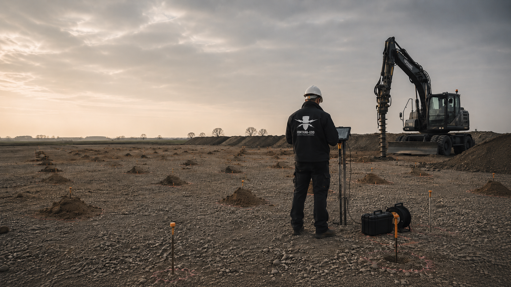
Before piled foundations, sheet piles, anchors, masts or ground investigation boreholes, developers and designers need an investigation of the subsurface envelope actually affected. Deep-ground and downhole surveys are specialist explosive ordnance survey services for this purpose. Send suspected-hazard records and the current plan with coordinates, depths and structural geometry so FONTANA-EOD can assess the drilling and survey strategy for your intervention.
Establish the point, alignment and target depth.
Agree the grid, method and casing.
Document survey profiles and limitations.
Deep-ground surveying is needed where a proposed ground intervention extends beyond the useful range of a surface survey or a suspect point at depth needs targeted investigation. Downhole surveys guide probes through positioned and usually cased boreholes. Whether one profile is sufficient or multiple survey boreholes are required depends on the target, interference and actual intervention envelope being assessed.
Records for strengthening works at Kirchhellener Straße near the A2 in Bottrop document 30 downhole surveys. View project details.
Service areas:Downhole magnetometry / deep-ground survey
The AMZL Goodman DNW5 project in Troisdorf documents 161 vertical downhole surveys. Other services included an investigation and clearance plan, and setting out. View project details.
Service areas:Downhole magnetometry / deep-ground surveySetting out and marking survey areasInvestigation and clearance plan
In downhole surveys, spatial conclusions depend on survey geometry, data quality and the target. An individual profile has limited lateral reach. If it does not adequately cover the working envelope, or interference requires it, several suitably arranged survey boreholes are interpreted together.
Show proposed foundations with coordinates, dimensions and depths. Where several plan revisions exist, identify the version used for technical coordination. Investigation scope relates to the construction task actually proposed. A general description as piled foundations does not by itself define the spatial envelope to be assessed.
Prepare foundation information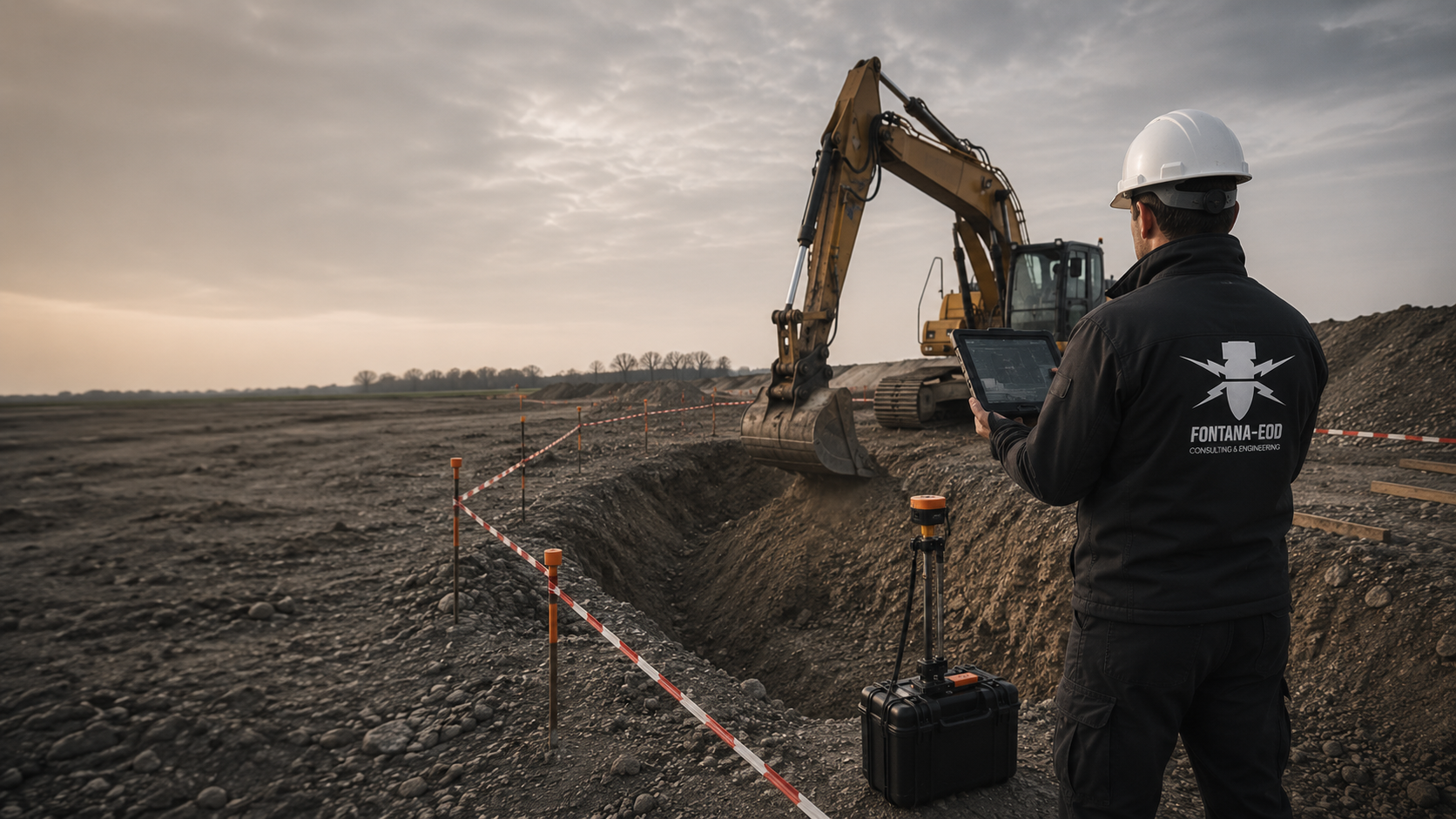
Linear structures are described by alignment and associated depths. Transitions and differing sections remain visible on the plan. Specialist planning can then assign existing results to the actual working envelope. Records for individual points are not extended to the entire proposed line without a spatial comparison.
Coordinate adjoining earthworks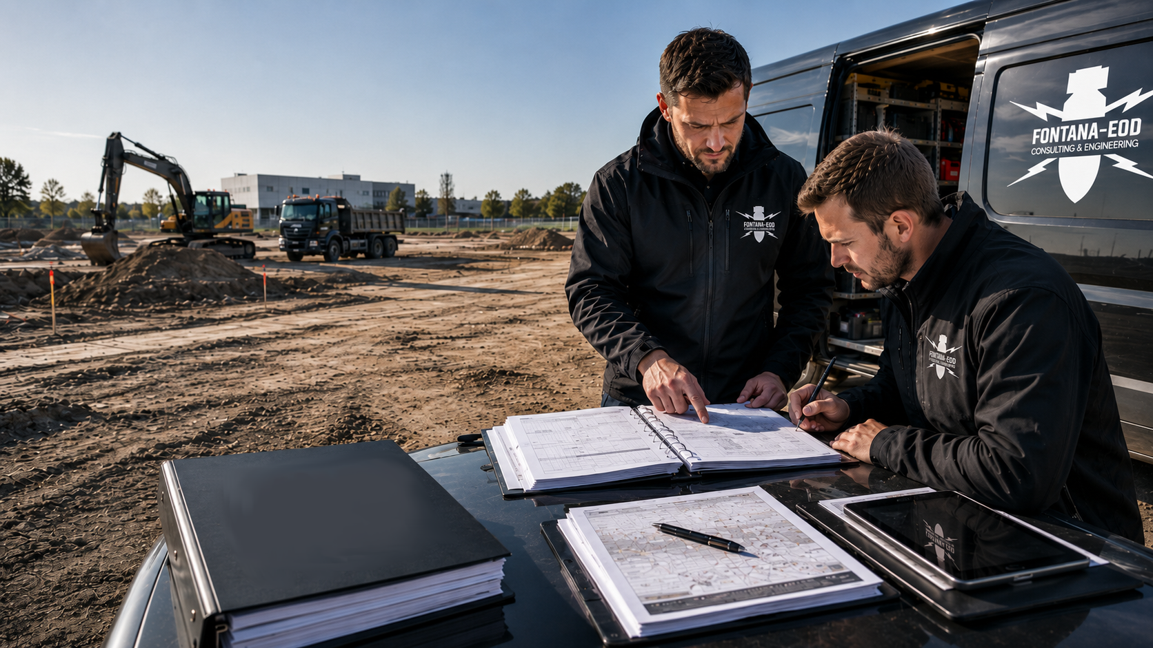
The position and extent of inclined structural geometry are shown clearly. A plan view may need supplementary sections. The actual intervention is compared with the documented investigation envelope. Design changes are provided before the relevant works so that the technical reference remains traceable.
Understand spatial documentationDescribe the proposed points and associated groundworks. Existing records are assessed against location and depth. The explosive ordnance assessment remains distinct from the subsequent geotechnical investigation. Project organisation brings the results together without conflating their different conclusions. One documented project example is downhole magnetometry for ground investigation along the A6.
Clarify investigation scope for borehole locationsDepth investigation does not begin with drilling. Historical assessment, near-surface investigation, drilling and survey planning, and subsequent investigation of anomalies serve different purposes. Each stage is used only where it answers the actual structural or suspected-hazard question.
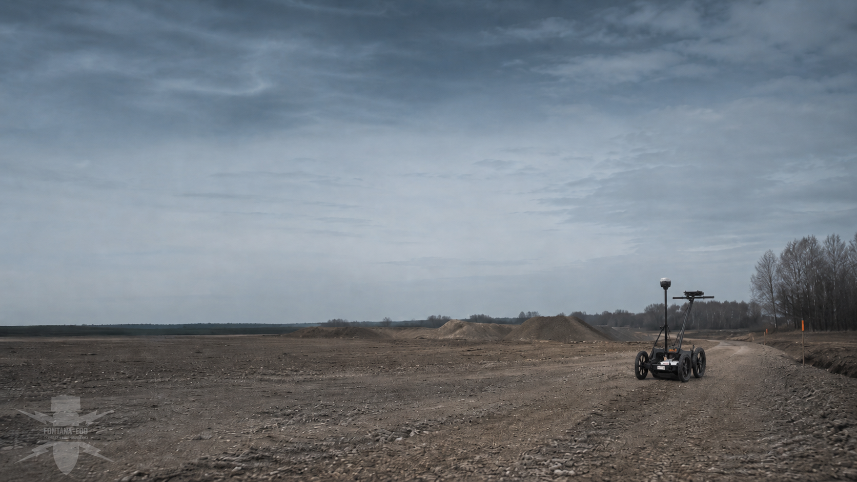
Downhole magnetometry requires the borehole starting point, creation of the survey path and surveying to be planned together. Under BFR KMR, the first borehole is advanced in sections and surveyed after each section. It is continued only where results show no anomalies. Unexpected resistance stops drilling and triggers a fresh local assessment. Construction and sequencing of neighbouring boreholes depend on the established survey range and borehole grid.
Conclusions apply to the planned borehole geometry and the subsurface envelope it covers. Borehole depth, spacing, arrangement, survey system and backfilling must therefore be defined together before execution.
Measurements are taken at controlled depth intervals and linked to position, final depth and borehole condition. Control surveys and plausibility-checked processing help distinguish instrument offsets, probe movement or local interference from reproducible anomalies.
Drilling and survey records link identifiers, actual coordinates, elevation reference, achieved depth and surveyed path to the depth profiles. Unreached areas, dominant interference and probe-movement restrictions remain identified explicitly. Documentation states the subsurface envelope that can actually be assessed.
Plan downhole surveysPiled foundations, sheet-pile alignments, shoring piles, masts and other deep structural elements affect clearly defined working envelopes. Surveys are referenced to the location, inclination, target depth, diameter and construction method of these interventions.
An area-wide survey at ground level does not automatically answer this question. What matters is whether the selected survey geometry covers the subsequent intervention envelope with traceable overlap.
For closely spaced piles or long shoring alignments, assessment checks whether the survey boreholes provide appropriate overlapping coverage. Edge points, changes in alignment and interfaces with existing structures are considered separately because their geometric and magnetic conditions often differ.
The results plan assigns profiles and assessment limits to current pile locations, shoring alignments or anchor corridors. Edge points and geometric gaps remain visible. Changes in position, diameter, inclination or depth are checked against this spatial assessment again.
Agree investigation geometry
Aerial photographs, maps, previous uses, known finds and existing statements indicate which targets and depth horizons may be relevant. This information determines whether an area-wide borehole grid, individual control points or investigation along a suspect alignment is required.
Historical assessment does not replace technical surveying at depth. It does establish survey objectives, priorities and spatial boundaries, preventing borehole locations being distributed without a reliable investigation question.
Assessment of suspicion may produce different priorities: a uniform area-wide grid, closer spacing around a suspect point or a linear arrangement along a structure. This reasoning makes the borehole plan technically traceable and verifiable for tendering.
The source register, image dates, suspect-area map and data gaps support selection of targets and investigation areas. Historical observations remain distinct from present-day survey findings. Their spatial reference and uncertainty are carried into borehole planning.
Assess the basis for suspicion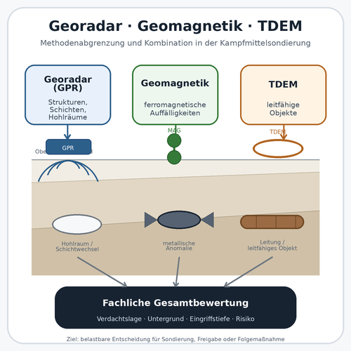
Magnetometry detects ferromagnetic anomalies, but steel, reinforcement and scrap may mask them. It helps define magnetic interference zones and relevant targets before deep survey boreholes are positioned.
TDEM measures electromagnetic responses from conductive objects. Utilities, large metal structures and survey geometry may limit interpretation. Any supplementary use is assessed for the additional information it can provide beyond the magnetic data.
In suitable ground, GPR can show layer boundaries, utility corridors and other structures. High ground conductivity and metal installations may limit conclusions. A radar reflection does not identify explosive ordnance.
Near-surface and downhole investigations address different depth and geometry questions. Combining them is useful where each step reduces a clearly defined uncertainty.
A preliminary survey can also identify areas where utilities, scrap or substantial installations prevent safe or meaningful use of drilling equipment. Alternative points or measures can then be included early in the construction sequence.
Surface profiles, sensor arrangement, positioning data and assessed anomalies are linked to the proposed borehole schedule. Survey gaps, masked zones and potential utility conflicts remain visible. A surface survey showing no anomalies is not extended to the full drilling depth without assessment.
Understand surface survey methods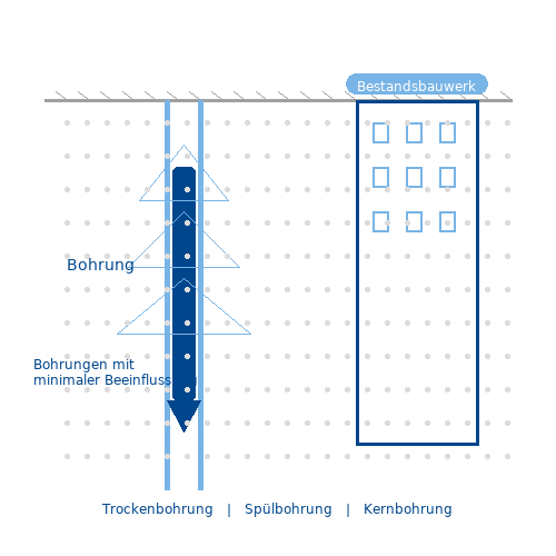
The drilling method is tailored to ground, groundwater, access, shoring, existing utilities and risk assessment. Casing and internal diameter must permit probe movement along the proposed survey path with little interference.
Utility and cable records are checked before work begins. Backfilling, groundwater protection and subsequent use of the borehole location must also be considered to keep surveying compatible with geotechnical requirements.
We select casing to guide the probe while minimising its effect on measurements. It must subsequently be removable properly or able to remain in the agreed condition. Differences between planned and achieved final depth are stated as actual survey limits, not replaced by calculated values.
The drilling record and casing information document the actual path, final depth, obstacles and condition of the survey path. These are compared with probe profiles and control measurements. Casing removal or retention and backfilling are referenced to the agreed completion condition.
Clarify execution requirementsFerromagnetic installations, casing, structures, utilities or unsuitable borehole geometry may restrict survey coverage. These limits are identified spatially rather than hidden by a blanket conclusion.
Depending on the situation, follow-up may include additional boreholes, another survey system, target investigation, area clearance, ordnance recovery or supervision tailored to the actual excavation.
Each limitation leads to a project-specific decision: an additional survey borehole, relocation of the structural element, controlled exposure, excavation in layers or reassessment after a design change. This identifies prerequisites still to be met before each deep intervention.
The follow-up decision remains linked to the point identifier, affected depth interval, survey limit and work performed. Exposure or area clearance adds findings and clearance records. Unresolved points and inadequately investigated areas are identified before the next construction activity.
For any subsequent area clearance, the clearance objective, working limits, depth and protective measures are defined. Access and interfering objects may restrict execution. Where surveying during construction is technically suitable, technical investigation and a specialist decision precede each stage of soil removal. Excavation then proceeds in layers under additional visual supervision, with repeated surveying to the proposed formation level.
Assess follow-up measuresShow the location, extent and depth of the proposed construction activity. Keep different design options clearly separated. These details underpin the spatial comparison.
Provide available specialist reports and project-specific information with their complete appendices. Their relationship to the current design is established during coordination.
Identify contacts for design, access and existing infrastructure information. Keep missing details identifiable so prerequisites for the proposed specialist work can be clarified selectively.
A pile, linear shoring alignment and inclined anchor affect different subsurface envelopes. The survey is therefore developed from the subsequent intervention and technically justified suspicion, not taken from a general area grid.
For piles, the alignment, diameter, embedment depth, pile-head area and sequence must be known. Investigation geometry follows the subsurface envelope actually affected rather than a general area.
The result describes investigated points and depths and remaining limitations. Changes in pile position or foundation method require reassessment of the spatial reference.
For pile groups, assessment also considers whether a shared grid covers overlapping working envelopes or whether individual edge and corner piles need separate control points. Current construction design is decisive, not an earlier outline design.
Linear specialist foundation works need traceable coverage along the entire alignment. Curves, corners, tiebacks and interfaces may require their own drilling or survey geometry.
Design and surveying must use the same spatial reference. Only then is it clear which alignment sections were actually investigated and where supplementary work remains necessary.
Documentation can be organised by chainage or alignment identifiers. This helps site management and specialist foundation contractors assign results and prevents a finally assessed section being confused with an unassessed continuation.
Vertical boreholes do not automatically cover inclined or horizontal working envelopes. Inclination, starting point, target depth and the intervention’s spatial path determine the appropriate arrangement.
Near existing structures, shoring or utilities, magnetic interference and safe drilling options are considered during planning.
For inclined elements, the three-dimensional path between start and target points is considered. Survey planning explicitly identifies corridor sections covered by vertical or inclined survey boreholes and areas where structural adjustments may be required.
Geotechnical boreholes, dynamic core sampling and monitoring installations enter the ground at individual points. Where explosive ordnance is suspected, the technical assessment of the proposed borehole location must be clarified before the geotechnical investigation itself.
The borehole schedule, coordinates, target depth, diameter and execution sequence underpin depth-specific investigation.
Where explosive ordnance and geotechnical investigations are coordinated in time, responsibilities, drilling sequence and hold points must be clear on site. Geotechnical investigation begins only after the proposed point has been addressed under the agreed explosive ordnance investigation strategy.
A mapped or technically derived suspect point requires its own investigation strategy. Location uncertainty, expected depth, target size, surrounding infrastructure and subsequent exposure options determine the number and arrangement of survey boreholes.
The survey does not automatically confirm an object type. It provides a reliable data basis for further specialist assessment and, where appropriate, targeted exposure.
To narrow down a location, survey boreholes may be arranged radially, tangentially or at varying density. Selection depends on uncertainty around the suspect point and whether the immediate objective is to refine its position or prepare controlled exposure.
Sheet piles, reinforced concrete, pipes, rails, foundations and near-surface scrap may mask magnetic signals. Borehole spacing and the survey system are planned so that interference can be recognised and treated separately during interpretation.
Zones that cannot be assessed adequately are documented and assigned a specific alternative, rather than applying one conclusion to the entire construction site.
Where possible, the report locates interference sources spatially and by depth rather than merely mentioning them. This allows subsequent assessment of whether an anomaly can be measured again outside the interference zone or requires another investigation method.
Comparable tendering needs more than a borehole count. The working envelope, ground, drilling technique, survey configuration and required conclusions must be described together.
Execution requires safe access, coordinated traffic and operating conditions, and clear lines of instruction and reporting. Soil moisture, hard surfacing and existing installations inform method selection. Signal quality and limitations remain documented alongside the depth actually surveyed or worked.
Borehole locations, alignments and reference points must use a common coordinate system. Relocations during design are recorded with version control.
At acceptance, planned and actual coordinates are distinguished; shifts within tolerances remain traceable.
Required investigation depth depends on the structure, construction method, suspected hazard and safety envelope. Measured depth and subsequent intervention depth are clearly distinguished.
Additional safety depths or overdrilling are specified only where technically justified and compatible with drilling equipment and ground conditions.
Grids, rows, individual points or inclined boreholes are arranged to investigate the relevant subsurface envelope for the required result.
Coverage is related to target size and location uncertainty; a fixed standard grid does not replace this assessment.
Drilling technique, diameter, casing material and borehole condition must permit safe construction and probe movement with little interference.
Drill cuttings, drilling fluid, stability and possible metal equipment components are considered in surveying and occupational safety.
Current utility plans, locating results, permission to excavate and information on foundations or shoring are required before boreholes are advanced.
Unclear utility alignments or missing as-built information remain unresolved planning inputs before the borehole location is executed.
Steel components, reinforcement, vehicles and metal infrastructure affect survey data. Distance, survey direction and interpretation methods are adapted accordingly.
Control profiles and repeat surveys may be required to distinguish reproducible signals from changing site influences.
Ground construction, groundwater, borehole stability, possible contamination and proper backfilling requirements form part of execution planning.
Reinstatement of the borehole location is coordinated with geotechnical design, environmental requirements and subsequent use.
Before work begins, establish whether the result is needed to assess borehole locations, design foundations, investigate a suspect point, support tendering or inform site management.
The agreed objective determines the detail of data, plans, limitations and assessment boundaries in the completion report.
Documentation must show where drilling took place, how measurements were made and the depth actually assessed. The drilling record, survey profile and site plan form a linked chain of evidence.
If anomalies are subsequently exposed or cleared, findings and clearance records supplement the survey documentation. Point identifiers, depth and location link them to the original finding. A survey profile alone does not demonstrate completed clearance.
Each point receives a unique identifier, coordinate, target depth, structural reference and work status. Linear works additionally record chainage and alignment sections.
Revisions and subsequent point relocations are identified so site management and the survey team use the same version.
Drilling method, final depth, diameter, casing, ground observations, obstacles and deviations are recorded for each point.
Unreached final depths, drilling obstacles and unusual ground conditions receive their own specialist assessment.
Probe type, number of axes, survey direction, measurement interval, zero and control checks, and relevant equipment settings are described transparently.
Equipment and configuration details must be sufficient for technical review of the survey and assignment of control measurements.
Raw data, processed profiles, signal patterns and anomalous depth intervals remain assigned to the relevant borehole.
Anomalous areas are assessed using depth, signal pattern, neighbouring profiles and interference, not just a point value.
Effects of steel, shoring, utilities, casing or incompletely constructed boreholes are identified spatially and explained technically.
Depth intervals that cannot be surveyed or are strongly masked are located spatially and assigned a specific follow-up decision.
The conclusion identifies assessed points and depths, further investigation needs and recommended follow-up measures.
Plans, tables and the written report use identical point identifiers, depth references and work statuses. Conclusions distinguish points with no anomalies, points that can be assessed only to a limited extent and points needing further work.
Each item of information remains linked to the actual borehole location and associated structural element. Even after design changes, this shows which survey was used for which geometry and depth envelope.
Historical assessment, authority records, earlier findings and project requirements are linked to the current borehole plan.
Historical evidence and previous technical findings are referenced to the point, expected depth and proposed structural element.
Setting out, actual coordinates, elevation reference and, where applicable, borehole inclination establish the spatial reference for surveying and reporting.
Planned and actual positions, coordinate system, reference points and point identifiers are documented to permit subsequent reproduction.
Drilling progress, ground changes, obstacles, casing, survey conditions and deviations are documented during execution.
Drilling equipment, method, actual path, final depth, casing and notable observations are compared with the survey plan.
Original data, processing steps, profiles, anomalies and control measurements remain traceable through to the specialist conclusion.
Zero checks, function checks, data completeness and unusual survey conditions are reviewed before specialist interpretation.
Each borehole receives a traceable status referenced to depth, surveyability, anomalies and any further measures.
Neighbouring depth profiles are considered together; unreached depths and interference-affected intervals remain explicitly visible.
Reports, borehole plans, records and data are handed over so that designers, site management and other parties use the same work status.
The report identifies which specific deep intervention the documentation supports and where further work remains necessary. Subsequent findings and clearance records, together with related authority correspondence, are assigned by point identifier and plan revision.
Changes to pile locations, shoring alignments and target depths are incorporated into drilling and survey design before execution. Previously investigated areas and newly added working envelopes remain distinguishable on the plan.
Pile plans, shoring alignments, anchor locations, borehole schedules and target depths are checked for clear spatial references and current revisions.
Historical and technical evidence is assigned to the actual point or depth envelope; unresolved data gaps are identified.
Borehole depth, spacing, arrangement, method, casing, survey system, quality checks and backfilling are defined for the project.
Existing records, locating information, access, equipment standing areas, protected areas and interfaces with site operations are prepared.
Borehole locations are marked and constructed using a method suited to the suspected hazard. The first survey borehole is deepened in sections with intermediate measurements; continuation, neighbouring boreholes and hold points follow the assessed results. The survey path is appropriately cased for probe movement.
The probe follows the defined depth intervals; survey conditions, repeats and anomalous intervals are recorded.
Signal patterns, interference and spatial plausibility are assessed and compared with neighbouring boreholes and project information.
Borehole status, limitations, supplementary investigations and agreed next steps are assembled for the project file.
Survey boreholes provide linear information. Technically justified positioning and combined interpretation are needed to reach conclusions about a pile, alignment or suspect area.
A deep borehole alone does not establish that the proposed construction envelope has been adequately investigated. Borehole spacing, arrangement, survey path, probe type and structural geometry are considered together. A profile shows magnetic conditions along a borehole. Whether it is sufficient or further boreholes are required depends on the investigation envelope and measured interference.
Casing keeps the borehole open and guides the probe. Material, internal diameter, installed condition and possible metal components affect surveyability. Casing and the survey system are therefore planned together. Removal or retention and backfilling after completion must be defined according to use, soil mechanics and groundwater protection.
Interpretation considers more than individual amplitudes. Signal shape, depth, repeatability, directional components and comparisons between neighbouring boreholes help distinguish local object responses from broader interference. Near sheet piles, reinforcement or steel foundations, a three-axis system can provide additional directional information; conclusions still depend on geometry and distance.
A borehole location can be assessed only within the area actually covered by the survey. If drilling ends early, the probe cannot reach target depth or a metal structure dominates the data, the affected depth interval is shown as restricted. This leads to a specific decision: another borehole, a different arrangement, another measurement principle or adapted construction.
For piles, sheet piles and anchors, the subsequent working envelope is the decisive reference. If structural design changes, existing surveys must be assigned spatially again. Documented point clearance cannot be extended to relocated or deeper structural elements without assessment.
Grids and rows are derived from the target, expected location uncertainty, probe range and structural geometry. A standard spacing applied by formula does not replace this planning.
Vertical boreholes suit many point and alignment tasks. Inclined survey paths may be required to assess anchors, raking piles or spatially offset working envelopes.
The probe must move along the survey path without jamming and with reproducible positioning. Non-magnetic casing and documented depth marks support data quality.
Vertical gradiometers measure defined field gradients. Three-axis systems provide additional spatial directions and can better describe complex interference, but still require suitable geometry.
Measurement steps, direction of travel and repeats are selected so anomalous intervals can be checked reproducibly and neighbouring profiles compared technically.
A signal is assessed by depth, extent, shape and surroundings. The survey produces a technical anomaly, not automatic identification of an object.
The final assessment assigns the investigated depth range, limitations and permissible next project step to each borehole location.
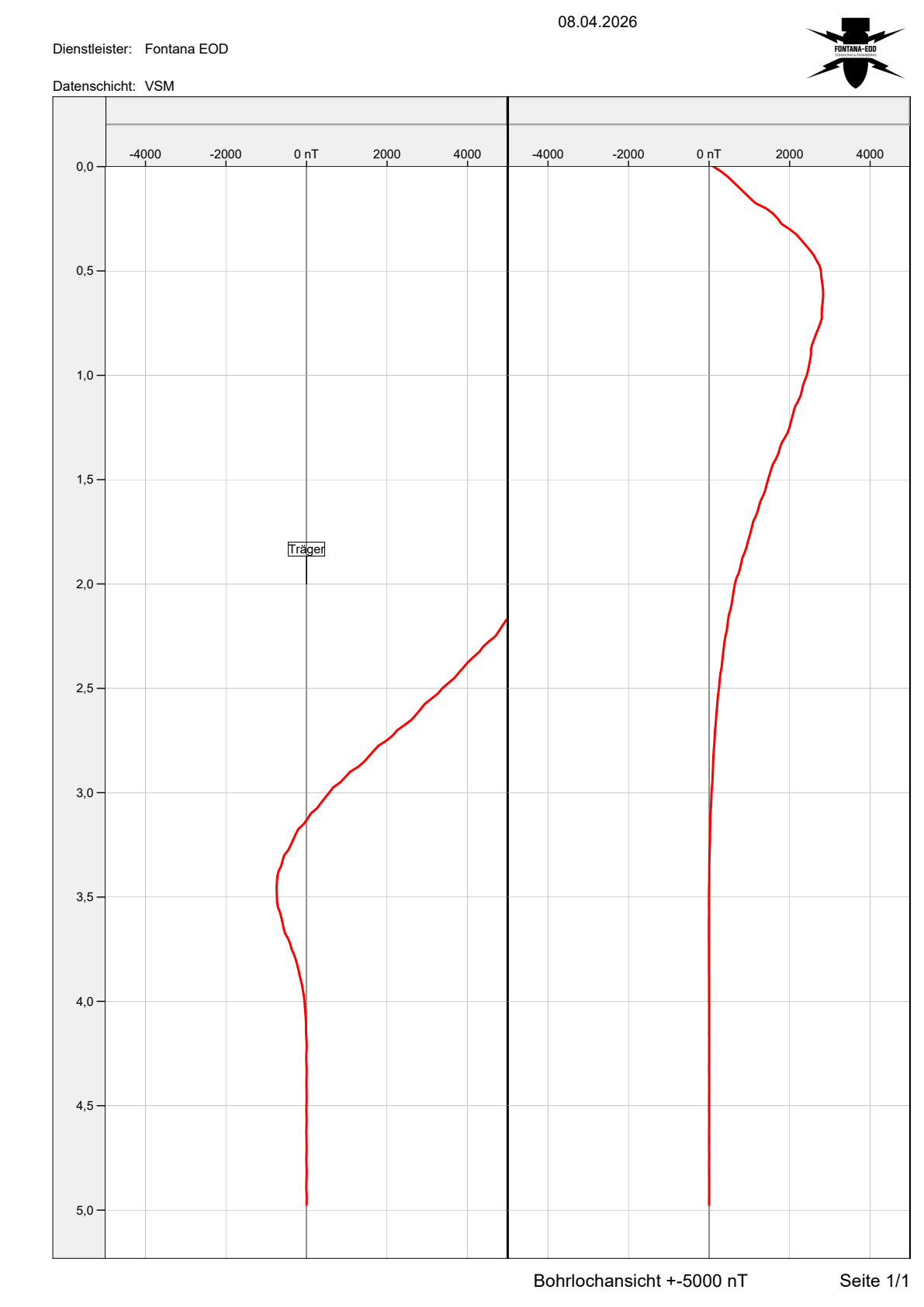
The report dated 13 April 2026 documents a downhole survey for a railway construction section in Landstuhl. Four borehole starting points specified by the client were investigated magnetically at depth and positioned using GPS. An interpretation depth of 5.0 metres is stated for this commission. The extract shows two of the four associated borehole profiles.
The red curves show magnetic measurements against depth. A deflection alone determines neither an object’s type nor its hazardousness. Specialist assessment considers the measured field and proposed intervention. The project report records that no anomalous points were detected. Partial clearance applies only to the investigation scope defined in the associated plans. Neighbouring areas and changed construction plans are not automatically covered.
Surface measurements, downhole magnetometry, radar, exposure and excavation supervision provide different types of information. Selection depends on the target, depth, structural geometry and interference.
Answers: ferromagnetic anomalies on accessible sites with sufficiently little interference.
Limitation: deep point interventions and areas near substantial steel structures are not automatically covered.
Answers: magnetic anomalies along defined survey boreholes and within the depth envelope they cover.
Limitation: Conclusions and coverage remain dependent on borehole spacing, arrangement, survey system and interference.
Answers: additional spatial components of a magnetic anomaly, particularly in complex geometries.
Limitation: More components compensate neither for an inadequate borehole arrangement nor for insufficient distance from dominant steel structures.
Answers: structural and dielectric anomalies around suitable boreholes.
Limitation: Ground conductivity, borehole condition and the absence of definitive material identification limit interpretation.
Answers: the actual cause of a prioritised anomaly through controlled intrusive investigation.
Limitation: Protective arrangements, access and regional responsibilities must be clarified before the intervention.
Answers: Which excavation layers were technically surveyed and assessed by specialists before removal under additional visual supervision. The next layer is investigated again. Technical suitability for the actual working envelope is a prerequisite.
Limitation: unsupervised areas and depths, and changed construction sequences, remain outside the conclusions.
Historical images and other available records establish spatial grounds for suspicion and help define expected targets and investigation areas.
Image quality and temporal coverage limit the conclusions. The report documents suspect areas and data gaps; a suitable technical investigation establishes present-day object locations.
TDEM records time-dependent electromagnetic responses from conductive objects. It can add information where magnetic data alone is insufficient to answer an unresolved question.
Utilities, reinforcement, large metal objects and survey geometry may limit interpretation. Spatially referenced survey data and assessed anomalies must be distinguished from object identification.
Reliable depth investigation requires everyone to use the same borehole plan revision, coordinate system and clear communication arrangements.
Define the construction task, programme, investigation area and required conclusions. Provide current plans, suspected-hazard records and access, and decide on follow-up measures.
Provide pile, shoring and anchor geometry with coordinates, depths, inclinations and construction methods. Changes are incorporated into investigation planning in good time.
Coordinate drilling methods, equipment, casing, equipment standing areas, ground and groundwater conditions, and interfaces with geotechnical investigation.
Operate probes, perform quality checks and acquire data according to the agreed design. Anomalies and limitations are documented immediately.
Assesses suspected hazards and structural geometry, develops the depth-related investigation strategy, coordinates surveying and documentation requirements, and assesses the project-specific next step.
Depending on the federal state and findings, handle hazard response, finds and decisions on further measures. The interface is prepared for the specific project and location.
The responsibilities of KBD, KMBD or KRD and local public-order authorities vary by location. Building control may be involved in the construction project. Existing requirements are supplied with dates and area references; competent bodies and reporting arrangements are clarified for the actual project site.
Downhole surveys combine drilling, geophysical measurement and potentially intrusive follow-up work. Risk assessment, qualifications, technical specifications and regional responsibilities are therefore considered together before work begins.
For downhole magnetometry, the BFR KMR construction guidelines address borehole depth, spacing, arrangement, survey system, casing, backfilling, quality assurance and documentation. This framework is applied to the actual structure and site conditions.
Before boreholes are advanced, utility and cable records and permission to use the drilling area for the proposed operation are clarified. Ground, groundwater, contamination, existing structures and safe equipment positioning inform risk assessment.
Commercial activities involving explosive substances that require authorisation are carried out within the company licensing framework of section 7 SprengG. Responsible persons need the competence required under section 20 SprengG for the relevant tasks. DGUV Information 201-027 supports risk assessment and protective measures for explosive ordnance clearance work. Searching for found ammunition is itself expressly covered by section 1b(1), no. 3(d) SprengG; the purpose of geophysical surveying is therefore assigned to the necessary responsibility framework.
The First Ordinance to the German Explosives Act (1. SprengV) includes requirements for specialist competence and state-recognised courses. For drilling, geophysical surveying and potential follow-up works, responsible personnel’s qualifications are matched to the actual scope of activity.
DGUV Rule 113-003 concerns dismantling or destroying explosives or corresponding articles and also includes disposal of found ammunition. Its application follows that activity scope; downhole surveying and subsequent work involving a find are described separately during preparation.
The borehole location, utilities, working envelope, method, personnel, equipment and stopping criteria are defined as binding requirements.
Borehole condition, probe movement, anomalous signals and changes are recorded immediately and assessed by specialists.
Its location is checked and referred to a separately prepared follow-up measure with suitable qualifications and protective arrangements.
Investigated points, depths, limitations and follow-up decisions must agree clearly between the site plan and report.
Relocated, additional or deeper structural elements are checked against existing surveys again before execution.
Prematurely ended boreholes, blocked casing or dominant interference are identified as separate limitations with a follow-up decision.
Stop work immediately. Leave the object untouched and undisturbed and leave the immediate area. In Germany, notify the police on 110; outside Germany, use the local emergency reporting arrangements. Further measures are coordinated with the competent authorities.
The borehole plan, drilling record and depth profile use the same identifiers and elevation references. The assessed survey path can then be assigned to the proposed pile, shoring or anchor geometry.
The borehole starting point, equipment position and subsequent working envelope are coordinated spatially. Coordinates, elevation reference and target depths are essential to planning.
Specify borehole locations and target depths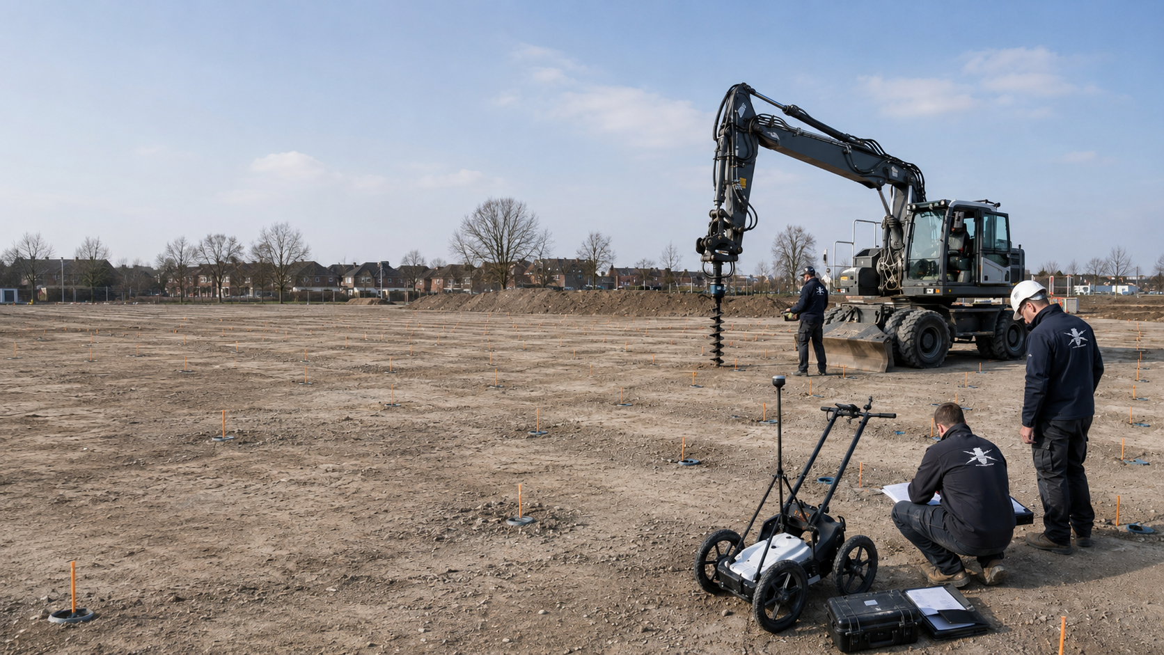
Grids, rows and individual points are derived from structural geometry, suspected hazards and the survey system, then positioned and documented.
Clarify the survey grid and depth reference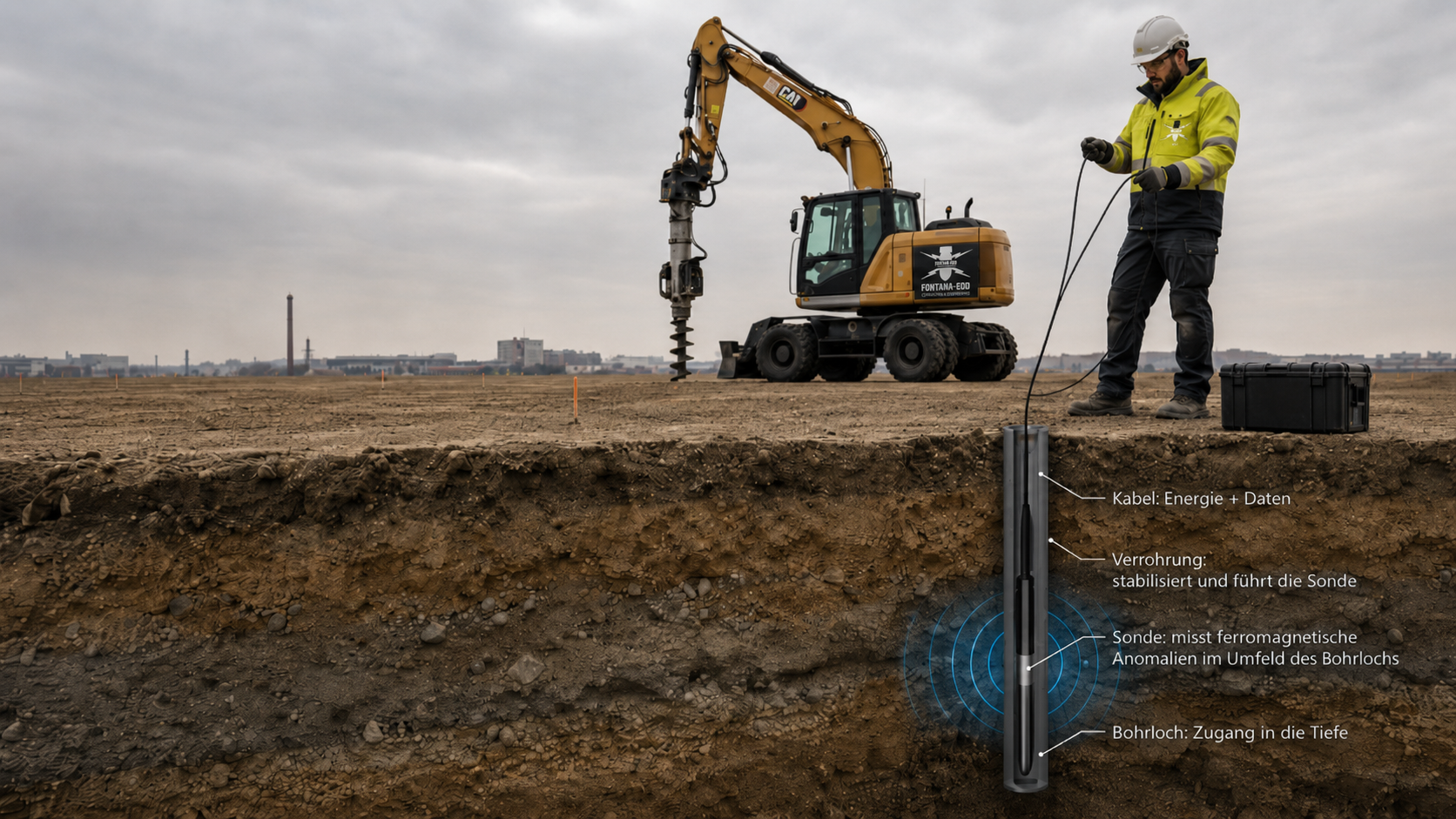
Casing material, internal diameter and installed condition affect measurements and are stated alongside the probe system used.
Match the task and methodUnder confined conditions, the starting point, spacing, equipment position and potential interference are assessed together before work begins.
Coordinate interfaces with ground intervention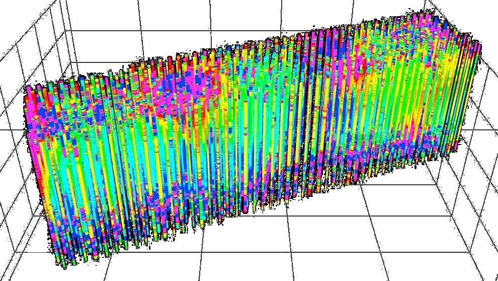
Interpretation shows which sections were covered, where signals occur and which depth intervals are restricted by interference or lack of surveyability.
Assign survey paths and documentation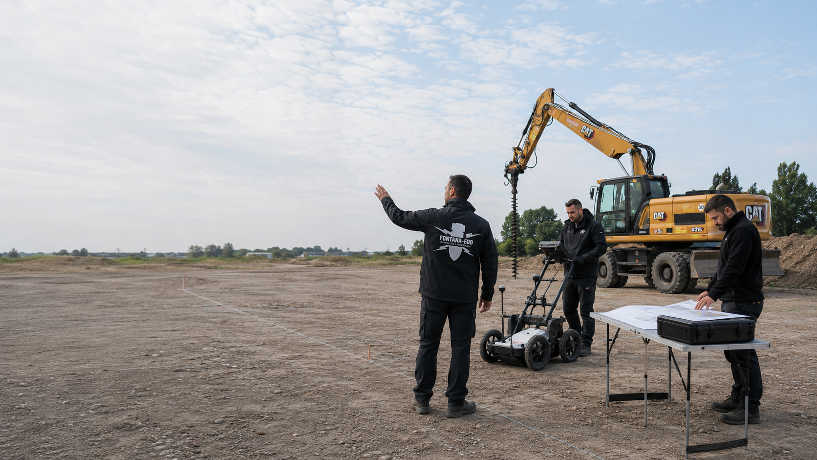
Early specialist assessment helps avoid poorly defined borehole grids, unsuitable survey configurations and later changes to the construction sequence.
Agree records before drilling begins
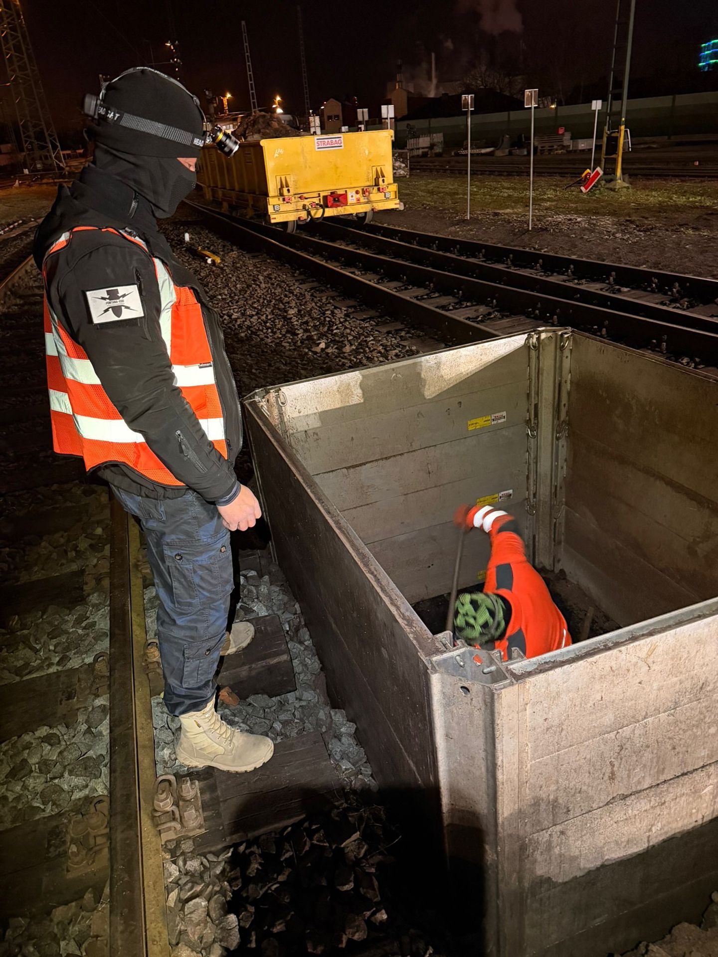
Deep-ground surveys remain tied to the defined point and depth envelope. Area-wide investigation, work on anomalous targets and subsequent recovery each require an appropriate service scope and their own documentation.
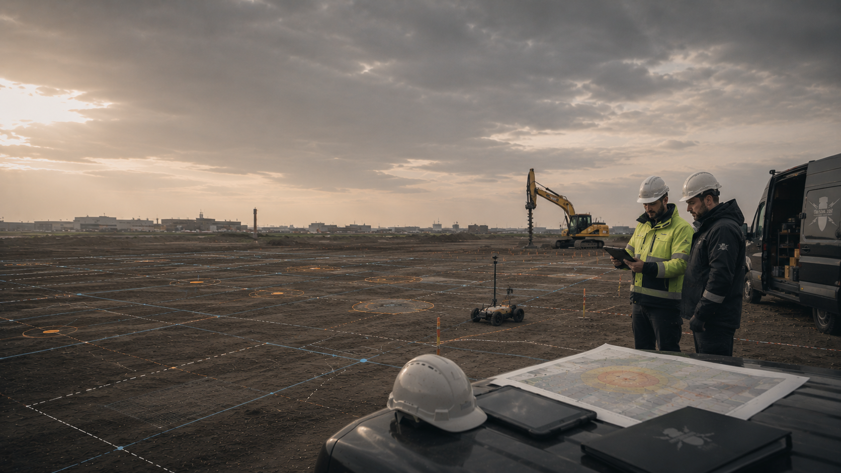
Consider historical assessment, surface and deep-ground surveys, clearance, recovery and documentation together.
Open the services overview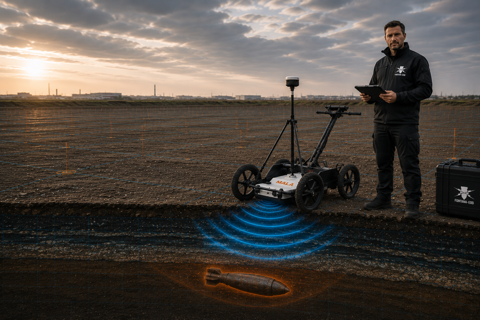
Compare GPR, magnetometry and TDEM for accessible areas and near-surface interventions.
Survey the surface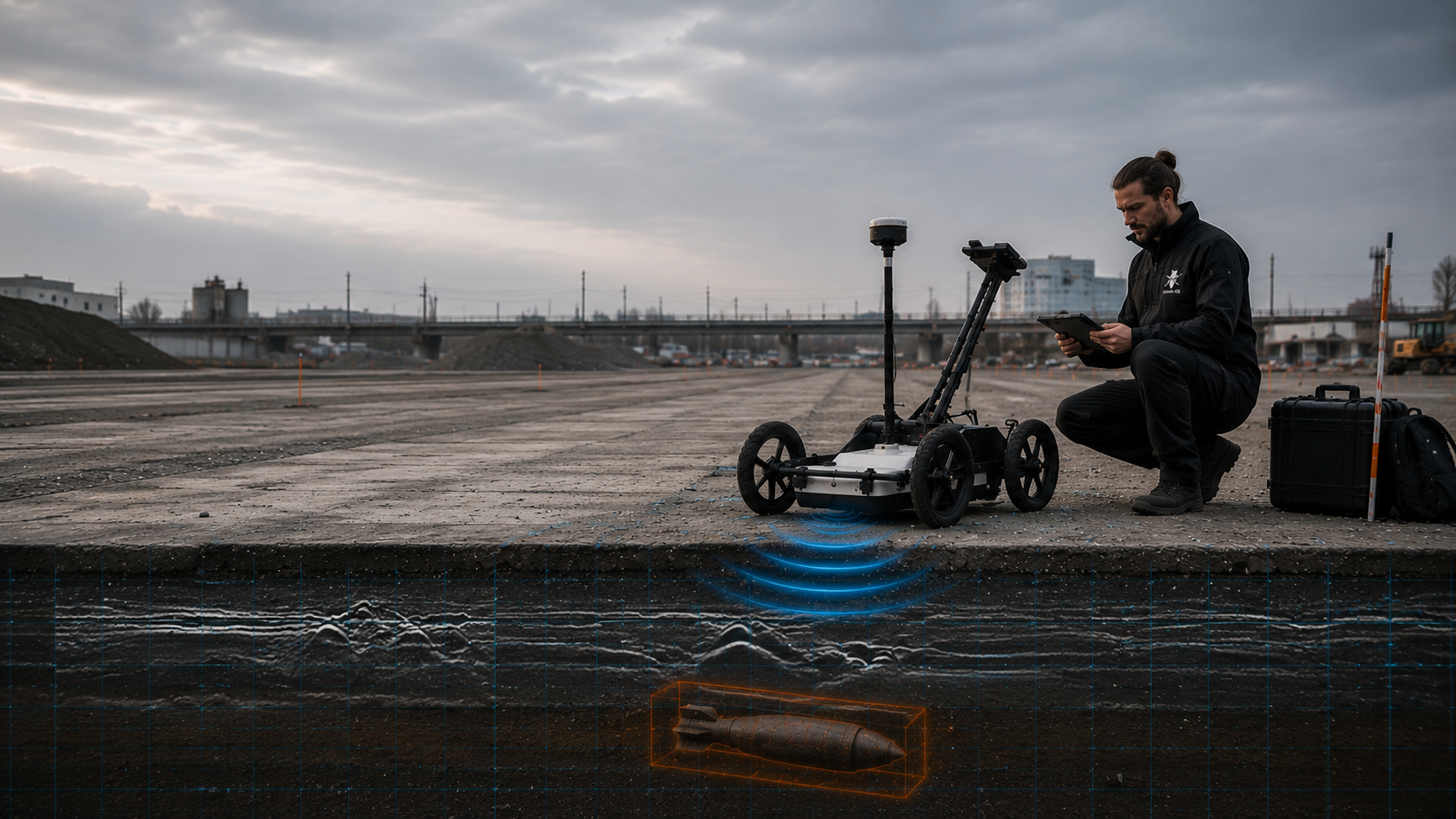
Assess subsurface structures, utility corridors and supplementary radar questions.
Open GPR guidance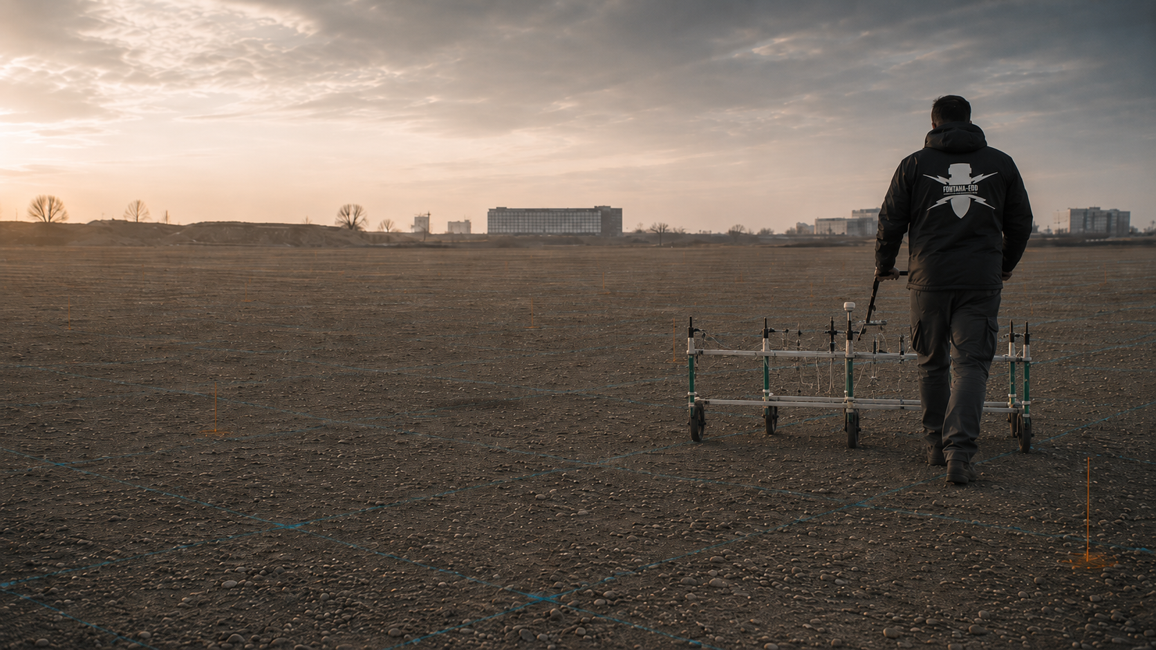
Explore area-wide magnetic data and its limitations compared with downhole measurements.
Open magnetometry guidance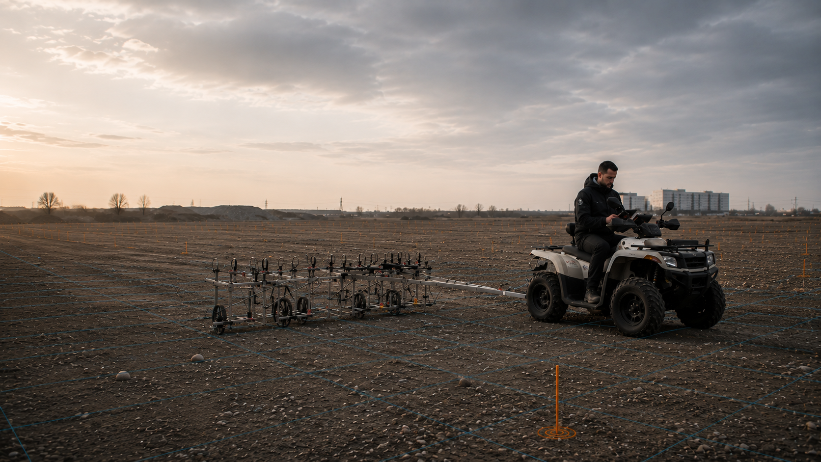
Assess time-domain electromagnetics as a supplementary surface method.
Open TDEM guidanceAddress areas that cannot be investigated adequately within the actual construction sequence.
Open excavation supervision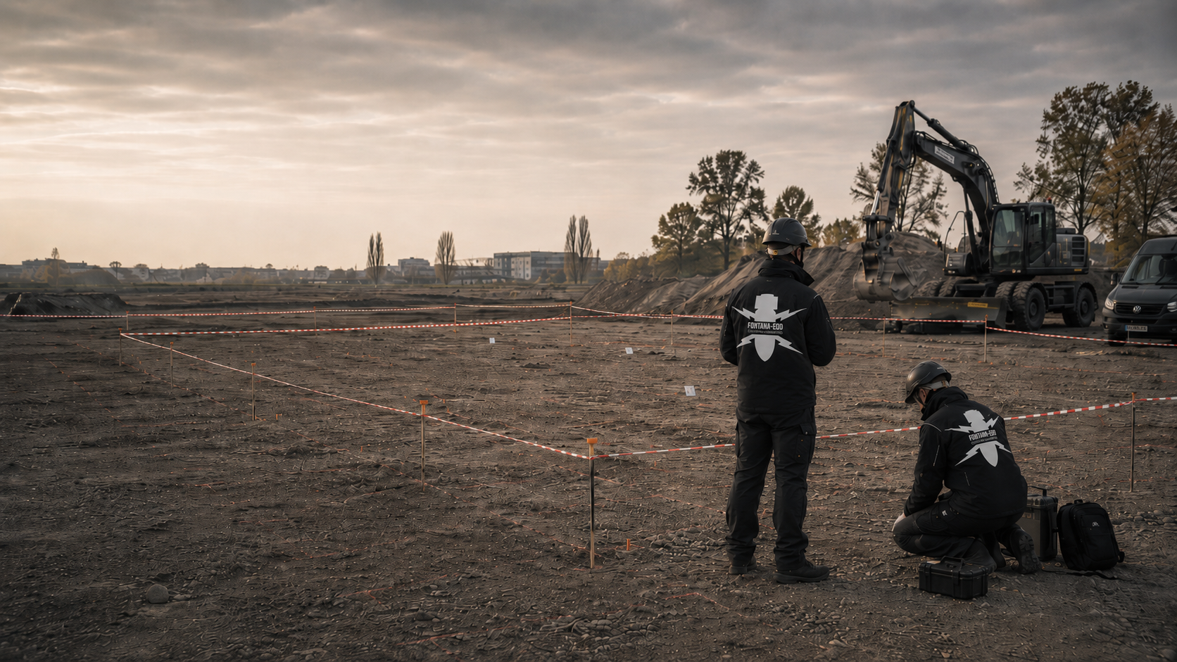
Explore anomalies, clearance objectives, exposure and documented working limits.
Open area clearance guidance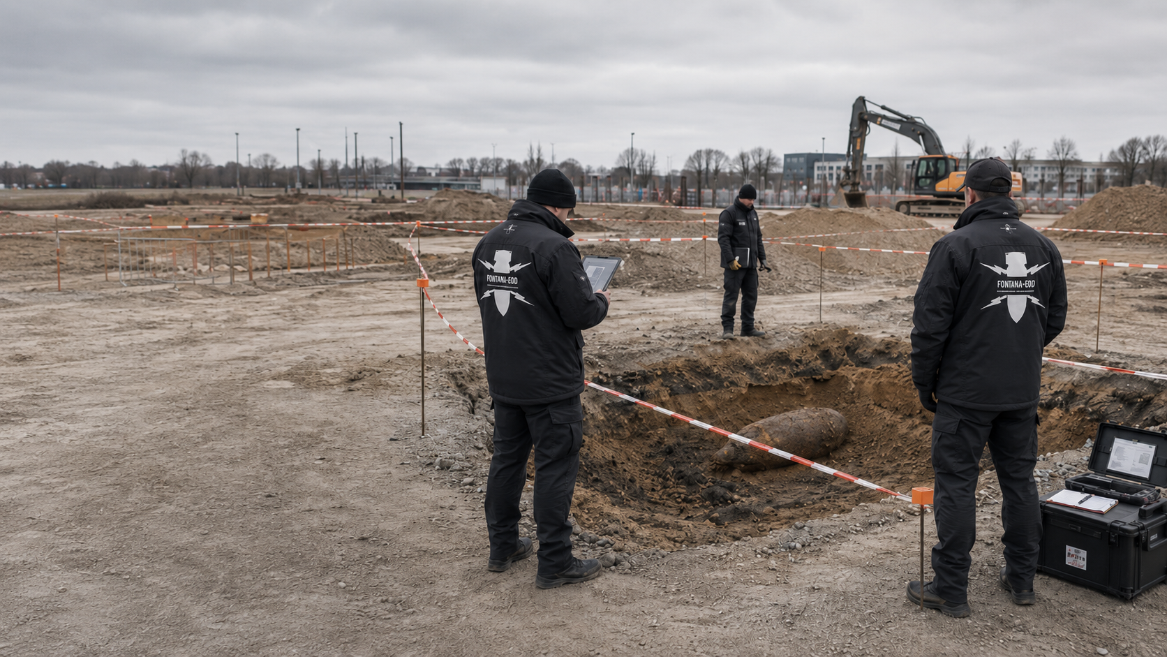
Understand responsibilities and the approach to identified ordnance-related objects.
Understand recoveryAgree borehole plans, survey data, limitations and follow-up decisions for the project file and site management.
Open documentation guidance
Explore project-specific requirements from railways, utilities, specialist foundation works, energy and geotechnics.
Choose the project settingFONTANA-EOD tailors specialist work to current plans and available evidence. The agreed scope defines the envelope to be assessed and the documentation needed. Subsequent conclusions remain tied to the work actually performed. Limitations and unresolved questions stay clear for the next project decision. Our references illustrate different commission sizes, with 149 downhole surveys in Neuss and five downhole surveys in Saarbrücken.
Discuss the investigation taskDesigners provide coordinates, depths and relevant elevation references. Changes are identified against the previous version. This makes it possible to understand the structural geometry underlying the assessment and whether the proposed construction still matches it.
Access, available working areas and known installations form part of preparation. The relevant project parties provide the required existing-infrastructure information. Unclear details remain identified. The specialist contractor tailors the task to achievable conditions and states unresolved prerequisites for the agreed scope.
Reports and spatial appendices are provided as a linked set. A point name alone or a short completion message does not adequately describe the investigated envelope. Site management can then relate the documented scope to the actual upcoming work.
A relocated point, different inclination or changed depth is checked against existing records. Earlier documentation is retained. An additional technical question is assigned specifically rather than extending the original conclusion to changed construction plans by default.
Before execution, the basis for suspicion, coordinates, target depths, drilling method, utilities, groundwater and documentation objective are considered together. Restricted survey coverage or relevant anomalies lead to a clearly defined supplement, such as another borehole, a different method, target investigation, area clearance or excavation supervision.
Send the current plan and existing reports during preparation. Identify options that remain undecided. Coordination can then establish which information is missing for a specific assessment and which subtask is already described adequately.
The structural information actually proposed is brought together with specialist planning. Access and site conditions are clarified through the relevant contacts. Before work begins, the agreed prerequisites are checked. Changes follow a clear communication route.
The report is read together with its spatial appendices. Proposed works must be locatable within the described investigation envelope. Unresolved areas remain identifiable and receive specialist assessment before conclusions are used for a further construction activity.
If additional points are planned, the new plan is compared with existing documentation. Work in a neighbouring area may provide useful information but does not automatically cover the addition. Further needs are described as a separate, traceable scope.
Construction decisions depend not only on whether a signal is anomalous. It also matters whether the proposed drilling or installation alignment lies entirely within the assessed envelope. Changes to coordinates, inclinations, diameters or target depths are therefore compared with survey records before intervention.
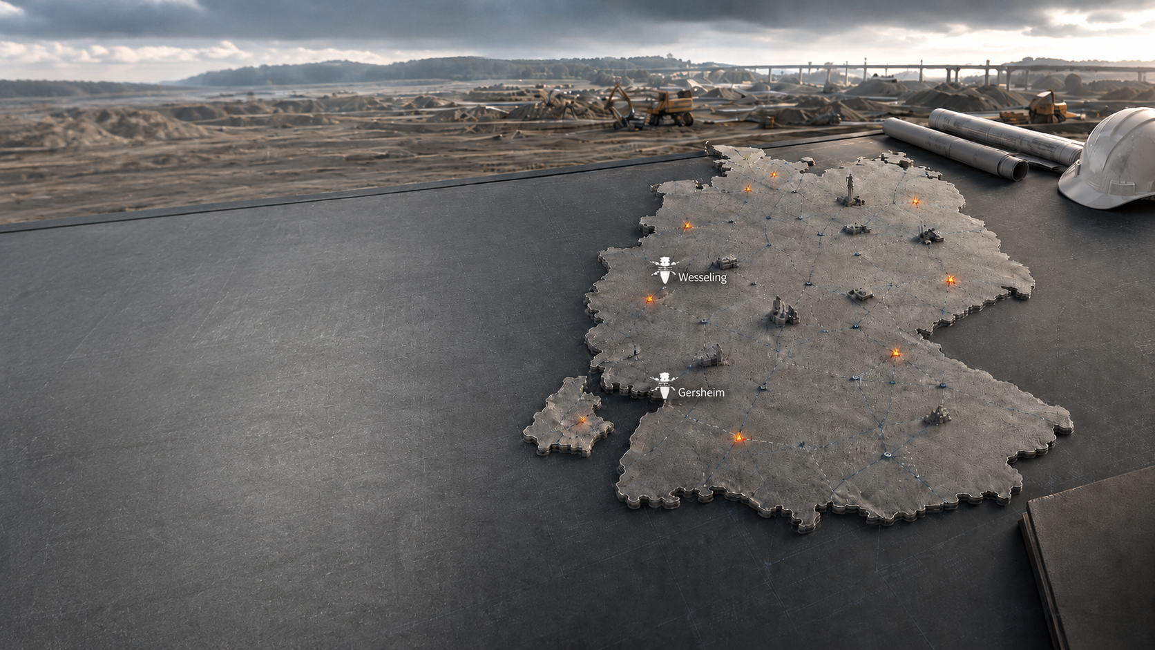
Provide the site, construction section and plan identifiers used. Location and depth information is supplied with its reference system. The regional overview helps orientation; specialist planning also needs precise assignment of each proposed intervention.
Provide project-specific information and previous reports in full. Their original plans and spatial boundaries remain identifiable. A conclusion from an earlier construction section is compared with current geometry before use for the new task.
Conclusions do not depend on achieved borehole depth alone. Spacing, arrangement, inclination, survey system, casing, magnetic interference and subsequent structural geometry determine the envelope that can actually be assessed. A single profile showing no anomalies cannot therefore be extended to neighbouring or relocated interventions without spatial assessment.
Documentation describes the envelope actually assessed and its conditions. For construction, the report, survey reference and construction plan are considered together. An individual depth figure does not replace this comparison. Unclear boundaries are resolved before different works are carried out.
Explore results and terminologyExplosive ordnance assessment, geotechnical investigation and structural design address different tasks. Project organisation combines their results for the actual works. A conclusion from one discipline does not automatically confirm every other prerequisite for the intervention.
Understand the service scopeFor later changes, position, dimensions, inclination and depth are compared with the documented scope. Existing records remain the basis. The comparison shows which findings still apply and which additional question requires investigation.
Explore results and terminologyTechnical information
The brochure explains investigation of deep ground using downhole magnetometry. It shows the information needed for planning and how surveying, interpretation and subsequent ground interventions are coordinated.
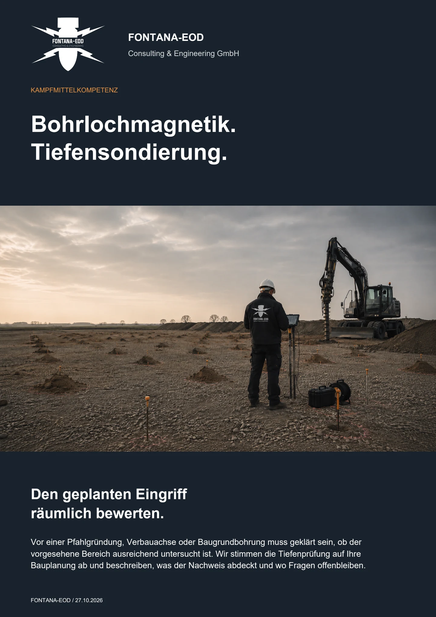
It becomes relevant where piles, sheet piles, anchors, masts, ground investigation boreholes or other deep interventions are planned and near-surface investigation does not adequately assess the actual working envelope. Suspected hazards, structural geometry, target depth, construction method and existing interference are decisive.
Clarify the task before tendering and ground disturbance wherever possible. Records review, method planning, execution, assessment and handover are tailored to the upcoming construction phase.
Deep-ground surveying is the umbrella term for technical investigation of ground at depth. Downhole surveying is a specific method in which probes are guided through planned, usually cased boreholes. Conclusions depend on survey geometry, data quality and the relationship to subsequent ground intervention. Depending on interference and the working envelope, one or several survey boreholes may be required.
Borehole spacing and arrangement are derived from the target, expected location uncertainty, required depth, survey system and structural geometry. Pile locations, linear shoring alignments and inclined anchors require different grids or survey directions. A general standard spacing does not replace project-specific planning.
Sheet piles, reinforcement, steel foundations, pipes, metal casing, vehicles and near-surface scrap may mask magnetic signals. Incomplete or unstable boreholes also limit the survey path. These effects are documented by point and depth.
The survey records magnetic or other geophysical anomalies and supports location and depth assessment. It does not automatically determine the actual object type. Definitive identification may require controlled exposure and involvement of the appropriately responsible specialists and authorities.
If a suspicious object is found, stop work. Do not touch or move it. Leave the immediate area, warn others without putting yourself at risk and, in Germany, notify the police on 110; outside Germany, use the local emergency reporting arrangements. The competent authorities determine further action according to the actual find.
Documentation includes project and spatial references, a borehole schedule, actual coordinates, drilling and casing information, survey system, survey paths, raw and interpreted data, anomalous depth intervals, interference, unassessable areas and a point-specific follow-up decision.
Factors include the number and arrangement of borehole locations, target depth, ground, groundwater, utilities, equipment access, casing, survey system, interference, necessary control boreholes, data scope and construction periods. A reliable estimate therefore needs current plans and a clearly defined working envelope.
Current plans, suspected-hazard information and a clear description of the later deep intervention are often enough for initial assessment. More precise geometry allows the grid, survey system and documentation scope to be defined more accurately.
Send the point schedule, coordinates, alignments, target depths, diameters, inclinations, pile or shoring plan and proposed execution sequence.
Useful details include geotechnical data, groundwater, utility plans, foundations, shoring, possible contamination, access and standing areas for drilling and survey equipment.
Include aerial photograph assessments, authority correspondence, previous surveys, known finds and an explanation of how the result will be used in the project.
Current PDF plans and a tabulated borehole schedule help avoid transcription errors. For linear works, show chainage, section boundaries and changes of direction. FONTANA-EOD then assesses which information is still missing for drilling, survey configuration and documentation.
Define service boundaries, data formats and treatment of unreachable depths in the specification. Describe necessary control boreholes and the deadline for plan changes. New or relocated points must be notified, assessed and added to the current borehole schedule. This allows checks of which structural elements have been investigated and which remain uncovered.
Project address, coordinate system, land parcel, construction site and reference points.
Target depth, embedment depth, borehole diameter, inclination and construction method.
Utilities, steel components, reinforcement, vehicles, installations and existing buildings.
Basis for assessing borehole locations, foundation design, suspect points, tendering or the project file.
Whether historical aerial photograph analysis, explosive ordnance surveying, surface surveying using GPR, magnetometry or TDEM, deep-ground surveys, downhole surveys, excavation supervision, area clearance or ordnance recovery is needed depends on the location, ground disturbance, depth, ground and existing documents. An early ordnance assessment provides clarity for tendering, programming, occupational safety and construction.
FONTANA-EOD combines its Section 7 SprengG licence, specialists holding Section 20 SprengG certificates of competence, suitable survey and clearance methods, and traceable documentation. Send the site plan, depth of ground disturbance, construction phase and existing documents for an initial technical assessment.


