Project pathway
The quickest route to the right decision.
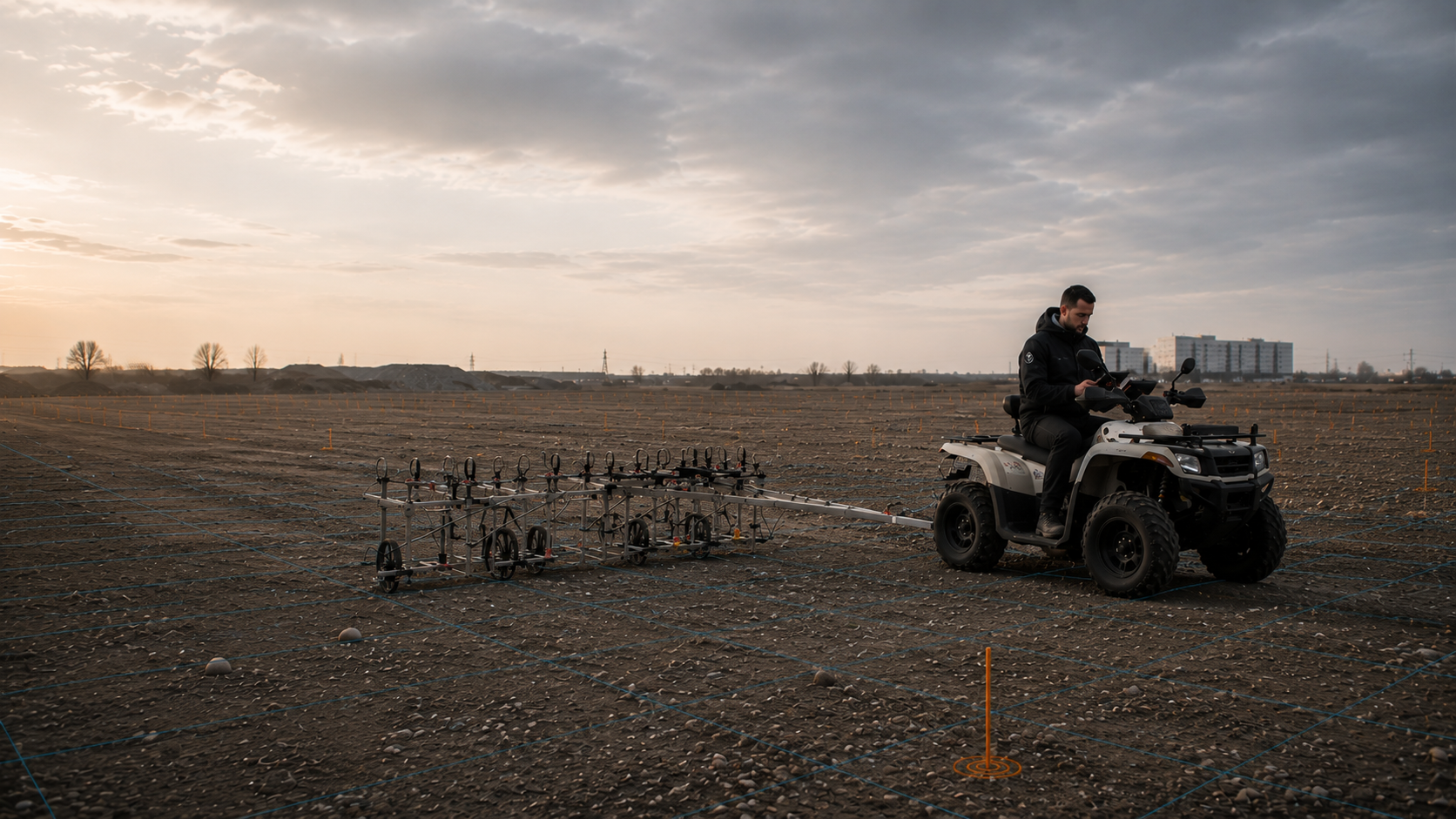
Before excavation, route works or foundations, clients and designers must clarify whether TDEM can detect the objects sought in the proposed space affected by the works. TDEM stands for Time Domain Electromagnetics and measures the time-dependent electromagnetic response of conductive metal objects. Send the site plan, intervention depth and documents on the suspected hazard so that FONTANA-EOD can assess suitability, coil geometry, survey scope and the evidence needed for your site.
Compare the target object with the interference field.
Define the coil, grid and spatial reference.
Assess time channels and anomalies.
TDEM is an active electromagnetic method for investigating conductive metal objects and can supplement an ordnance survey where the target object, depth range and survey environment are suitable. After the generated field is switched off, the decay of the object response over time is measured; this initially produces a technical anomaly, not a positive identification of ordnance. Coil geometry, survey grid, interference sources and required data are therefore defined before commissioning so that the result supports a specific decision on further investigation or work.
TDEM records the electromagnetic response of conductive bodies. Magnetometry responds to ferromagnetic objects, while ground-penetrating radar responds to material differences below ground. The appropriate survey or combination for your project depends on the basis for suspicion, area and planned intervention.
After relevant findings have been clarified, area clearance with a defined objective may be needed for a delimited suspected area. Accessibility, interfering bodies, depth and protective measures determine how it is carried out. Findings and clearance records connect the actual work with the preceding anomaly list; unresolved targets and untreated zones remain identifiable.
The method induces eddy currents in conductive bodies and measures the decay of the secondary field over time. Depending on the system, several time channels, different coil sizes or several receiver areas can be used to assess signal strength, spatial extent and decay behaviour.
The conclusions depend substantially on object size, shape, orientation, depth, coil dimensions, survey height and interference. TDEM is therefore suitable for clearly defined questions, not as a general replacement for historical investigation, magnetometry or depth-related assessment.
The TDEM evidence connects coil configuration, survey height, time channels and positioning data with the assessed secondary signals. Interference areas, unrecorded edges and technically unresolved anomalies are stated separately so that the next investigation can address a specific information gap.
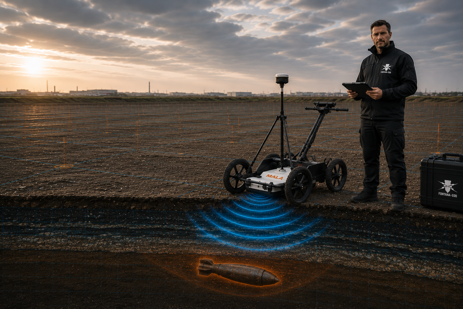
Compare survey methods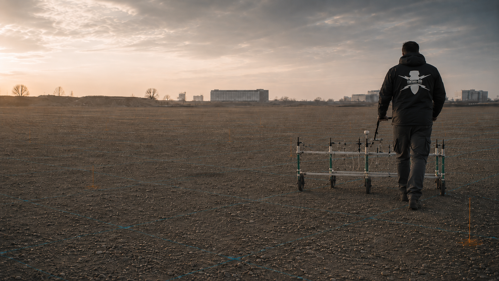
Magnetometry measures changes in the natural Earth’s magnetic field and is particularly sensitive to iron-containing or ferromagnetic bodies. On open sites with little interference, it can provide high survey productivity and dense, georeferenced anomaly mapping.
Magnetic infrastructure, reinforcement, rails, vehicles and metal-rich topsoil can strongly mask the data. TDEM can supplement them in suitable cases because it responds actively to conductivity; however, extensive metal structures and services also affect electromagnetic measurements.
Magnetic data, sensor handling and spatial reference are documented in anomaly and interference-zone plans. When compared with TDEM, the different survey principles and limitations remain identifiable. The combined assessment states what each dataset contributes to interpreting an anomaly.
Understand the scope of magnetometry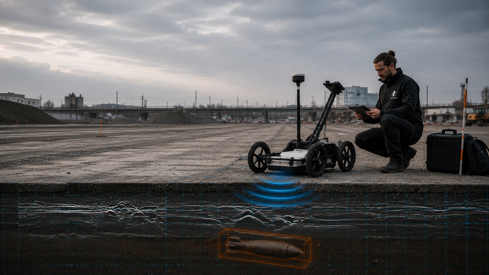
Ground-penetrating radar emits electromagnetic pulses and records reflections at changes in material and moisture. It can show layer boundaries, made ground, service zones, foundations, voids and individual spatial features, provided the ground and survey frequency allow sufficient wave propagation.
TDEM and ground-penetrating radar answer different questions. A conductive object can produce an electromagnetic anomaly without being unambiguously interpretable in radar; conversely, a non-metallic structure can produce a clear radar signal without causing a TDEM anomaly.
Radar profiles and assessed structures are handed over with profile direction, spatial reference and usable depth range. Combined interpretation shows which structural information comes from radar and which conductive anomaly comes from TDEM. Agreements and unresolved causes are explained technically.
Define the technical role of ground-penetrating radar
Historical investigation describes why suspicion exists, which subareas may be affected and which links to ordnance or events matter for technical investigation. It helps define survey areas, priorities and expected target objects traceably.
This basis is important for TDEM because coil size, interpretation parameters and relevance thresholds must suit the expected object and planned intervention depth. A technical survey without a sound question may produce many signals without improving the project decision.
The historical report identifies the image and archive sources used, their spatial reference, assessed suspected areas and data gaps. This supports the choice of areas and object types relevant to the TDEM survey plan. Historical conclusions remain distinct from current survey findings.
Prepare the basis for suspicion
Piles, sheet piles, anchors, geotechnical boreholes and other deep interventions require assessment of the specific point and depth space. A TDEM surface survey does not automatically cover this geometry, particularly where the required depth is beyond the range that can be reliably investigated.
Coordinates, design depth, drilling method, diameter and the space affected by the works determine whether downhole magnetometry, borehole radar, electromagnetic additions or other depth-related methods become necessary.
The point list and supporting evidence connect coordinates, drilling and survey geometry, intended and achieved assessment depth and limitations. They are checked against the actual pile, borehole or retaining works space. Changed points and additional depths require the technical findings to be related to them afresh.
Assess the depth investigation
Existing buildings, services, substantial reinforcement and large metal bodies can limit TDEM interpretation. A suitable further investigation is defined for these areas. An ordnance survey during construction requires that it can assess the actual excavation space adequately from a technical perspective.
The technical survey and specialist decision take place before each removal of ground. The defined layer is then excavated with additional visual checks. This sequence is repeated down to the planned formation level. Equipment operation, stop points, instruction channels and communication of finds are agreed before work begins.
Layer and section records assign the technical survey, specialist decision and excavation to the same space affected by the works. Findings, stop points and insufficiently assessed areas remain linked to the construction conditions. Handover describes the section actually worked and the outstanding measures.
Understand excavation supervision requirementsDoes an entire site need its first survey, or does a known anomaly need remeasurement? Both tasks may suit TDEM, but require different survey configurations. The objects sought, relevant depth range and existing interference sources are clarified first.
Area mapping, repeat measurements of selected anomalies and more detailed classification are different tasks. Each requires appropriate grids, coils, time windows and acceptance criteria. Planning and costing must therefore establish whether the first task is to assess a continuous area, check an existing anomaly list or prioritise a limited number of suspect points for the next stage.
Services, reinforcement, shafts, foundations and metal installations generate electromagnetic responses that can overlap possible target signals. Site plans, accessible areas and dominant interference sources are brought together before surveying.
TDEM is useful where a justified electromagnetic question remains despite these conditions. Uninterpretable edges and areas persistently dominated by interference are identified spatially and assigned a follow-up measure.
Heterogeneous fill may contain numerous small metal objects and varying conductivities. A suitable coil configuration can weight small near-surface pieces differently from larger, deeper objects; however, their effects cannot generally be excluded completely.
Relevant object sizes and depths and known metal interference are considered in advance. Strong overlap may require a subarea assessment or targeted investigation of individual anomalies. An ordnance survey during construction is an option only where technically suitable for the actual space affected by the works.
Asphalt, paving or compacted surfaces can allow surveying without ground intervention, provided the survey frame can be guided evenly and no extensive metal structures dominate the site. Height steps and varying separation affect signal strength.
Survey direction, track spacing, reference points and areas inaccessible to vehicles are checked on site. The result is compared with as-built plans and visible installations.
On utility, railway or transport projects, surface conditions, interference and intervention depth may vary by section. A uniform survey system does not necessarily provide equivalent conclusions along the entire route.
The route is divided into technically comparable sections. Survey configuration, data quality and required additions are documented for each section so that the project file does not create an apparently continuous conclusion.
Where magnetometry shows anomalies that cannot be sufficiently differentiated because of magnetic overlap or object geometry, TDEM can provide additional information on conductivity and decay over time. Both datasets must use the same spatial reference.
An additional TDEM survey must answer an outstanding question, such as the conductivity of an anomaly. The information it is intended to add is defined before commissioning.
For comparable procurement, the work area, target object, coil system, survey grid, positioning, data formats, interpretation, relevance criteria and documentation scope must be specified. General wording such as “carry out a TDEM survey” leaves essential quality characteristics undefined.
The evidence due should make clear which areas were surveyed under which conditions, which areas remained limited and what specialist follow-up decision arises from the data.
TDEM data result from the interaction of the primary field, conductive object, survey geometry and ground. Even small changes in survey height, strong conductivity variations or large metal structures can change the response. The main conditions are therefore defined before costing and fieldwork.
Edges, obstacles, changing survey height, interruptions and extensive metal structures are considered in the survey plan. They affect both fieldwork effort and later interpretability. Where tracks cannot be followed correctly or nearby metal bodies overload the system, the area must be identified spatially and linked to a suitable additional measure.
Preparation also includes safe access, traffic and operating conditions, responsible personnel and arrangements for reporting finds. Gaps and poor-quality data are documented spatially. The depth that can actually be interpreted, considered against the proposed intervention, determines the conclusions the report can support.
Material, expected size, shape, orientation and depth determine whether a sufficient electromagnetic response can be expected and which time windows are relevant to assessment.
The size and arrangement of transmitter and receiver coils affect range, spatial resolution and sensitivity to small near-surface objects. Larger does not automatically mean better.
The separation between coil and ground must remain as constant as possible. Uneven ground, vegetation, kerbs and obstacles change coupling and can produce apparent signal differences.
Track spacing, survey direction, acquisition speed and triggering must suit the target object. Excessive spacing may miss narrow anomalies; uneven tracks make area interpretation more difficult.
Moisture, clay content, salinity, made ground and small-scale material changes affect the early signal. Suitable time windows and a specialist plausibility assessment are required to separate the ground and object response.
Services, reinforcement, fences, rails, vehicles, shafts and extensive metal components can restrict the usable dynamic range or mask anomalies.
Survey data, interference areas and later targets need a common coordinate system. High sensor resolution loses its project value if position and work boundaries cannot be reliably assigned.
Raw data, time channels, reference measurements, survey gaps and deviations are documented. Uninterpretable areas remain visible and are not concealed by blanket statements about the site.
A coloured anomaly plan alone is not enough for designers and site management. Usable documentation connects project information, survey configuration, spatial reference, raw and interpreted data, interference areas and the specialist conclusion. The report also identifies the time channels used for assessment, survey areas limited by saturation or overlap, and how control measurements informed the conclusion. The assessment criteria remain traceable for later design and construction stages.
The conclusion distinguishes areas without project-relevant anomalies, zones that cannot be adequately assessed technically and anomalies requiring further investigation. These categories lead to different follow-up decisions. If area boundaries, time channels, filters or assessment rules change during processing, it also remains traceable which data and map version represents the status handed over.
The project name, site plan, parcel, coordinate system, construction area, route, chainage and surveyed subareas are clearly identified. Unsurveyed edges and obstacles are traceable on the maps.
Historical documents, authority records, known finds, planned intervention depth and expected target objects explain why TDEM was used and which signal types are relevant to the follow-up decision.
Transmitter and receiver geometry, coil size, survey height, time channels, grid, acquisition speed, positioning method and checks are described so that data acquisition can be understood technically.
Surface conditions, moisture, vegetation, services, reinforcement, vehicles, installations, terrain steps and other influences are documented spatially. Changes during surveying are identified.
Relevant signals are georeferenced, examined in the available time channels and compared with geometry, adjacent profiles, as-built data and the suspected hazard. Automatic marking does not replace a specialist plausibility check.
The report describes which areas and depths can be assessed under the documented conditions, what uncertainties remain and whether exposure, further surveying, specialist excavation supervision or another measure is required.
The interpretation must be traceable to the survey data and field record. Maps and the report show where measurements were taken, which data were used and how the conclusions were reached. It is particularly important to distinguish the surveyed area, the area actually interpretable and the area to which the later conclusion applies. These three levels are kept consistent in maps and text.
If surveying is followed by exposure, area clearance or recovery, the resulting findings and clearance records are linked to the preceding survey documentation. The record then identifies the stage actually completed and its limitations. Survey documentation alone does not claim that these follow-up works have already been completed.
The aerial photograph assessment, site plan, utility information, ground information and project requirements are assembled with their versions recorded. This makes clear what information underpins the survey plan.
Survey date, system, configuration, personnel, weather, site conditions, obstacles, survey gaps and deviations are recorded during the work and linked to the digital data.
The original measurements are retained as the basis for verification. Processing, corrections and filters are documented so that anomalous signals can be traced back to the original survey.
Relevant signals, known services, extensive interference, uninterpretable areas and work boundaries are shown within a consistent spatial reference.
The assessment distinguishes the measured finding, interpretation and recommendation. It identifies which project question was answered and what further measures are appropriate for unresolved or ordnance-relevant areas.
Reports, plans and data are prepared so that the client, designers, site management and, where appropriate, responsible authorities can use the same work status and limitations.
Before fieldwork, target objects, investigation depth, area boundaries and existing metal structures are clarified. The coil configuration, driving tracks and survey spacing can then be defined.
The process closely connects fieldwork and interpretation. Control tracks, reference areas and quality checks are included in the survey plan so that changes in survey height, saturation or unusual conductivity changes do not first become apparent in the final report.
The conductive targets relevant to the planned intervention and the area and depth space to be covered are defined. Existing site plans, utility documents and earlier survey reports are checked for spatial correspondence, currency and outstanding questions. For ordnance questions, it is clarified whether historical knowledge is missing. Any necessary historical research or aerial photograph assessment is related to the affected area and the unresolved question. Its result supplements the basis for suspicion on which the electromagnetic survey objective is founded.
Services, reinforcement, shafts, fences, installations, vehicles, surface changes and poorly accessible zones are located before field acquisition.
Coil dimensions, transmitter-receiver arrangement, survey height and usable time windows are matched to object size, required resolution and ground conditions.
Track spacing, overlap, survey direction, spatial reference and control passes are defined so that coverage and edge zones can be checked. Obstacles, omitted areas and deviations from the intended track guidance remain documented.
Driving tracks, sensor height, interruptions and changes in the surroundings are documented during acquisition; anomalous areas are checked immediately.
Early and later signal components are examined for ground response, overload, object response and spatial consistency before anomalies are delimited.
Relevant responses are prioritised by location, extent, decay behaviour and project relevance; known installations and explainable interference sources inform the assessment.
The report separately classifies interpretable areas, limited zones and anomalies requiring further investigation and identifies the appropriate next work stage.
TDEM does not directly measure object type or depth. It records the time-dependent electromagnetic response and derives spatial anomalies from it. Reliable interpretation distinguishes the measured value, processing, model assumptions and specialist conclusion.
Time channels are not assessed in isolation. Spatially recurring signals, a consistent pattern across several tracks and plausible decay behaviour strengthen the conclusions. Broad background responses, linear existing structures, abrupt height changes and isolated outliers are examined separately before a target point is derived. Interpretation therefore connects the temporal signature and spatial pattern.
For a sound tender, the survey objective, target object, required depth range and spatial work scope are established before equipment selection. The specification also includes the intended coil geometry, relevant time channels, spatial reference requirements, quality checks and data to be delivered. This allows assessment of whether an area TDEM survey, targeted repeat survey or combination with other methods genuinely answers the project question.
During excitation, the transmitter coil generates an electromagnetic primary field. Eddy currents arise in a conductive body. After the primary field is switched off, these currents decay and generate a secondary magnetic field, which receiver coils record in successive time windows. The time channels represent different parts of the decay curve. Ground and object responses, material, geometry and survey separation affect this pattern; a late time channel alone is therefore not a direct depth measurement.
The measured response is also influenced by material conductivity, magnetic permeability, object shape, orientation, separation and coil geometry. A similar signature can therefore have different causes. Reliable conclusions require spatial repeatability, several channels, known conditions and comparison with further project information.
Area surveys do not examine a single maximum value alone. The development of the response across several tracks and time channels is informative. It is equally important whether the anomaly remains reproducible in control measurements and how it relates to known services, shafts or metal installations. Outliers, edge artefacts and signal changes caused by changing survey height are separated from spatially consistent object responses. This check reduces the risk of treating a striking map colour as a relevant target without a sufficient data basis.
Interpretation must also suit the later ground intervention. An area-wide excavation may need different prioritisation from a narrow route or an individual foundation point. An anomaly outside the proposed space affected by the works is assessed differently from a signal directly within the intervention area. Conversely, a zone without conspicuous technical anomalies cannot support wider conclusions if obstacles, services or unfavourable coil geometry restricted its coverage. The area worked and scope of conclusions are therefore explicitly distinguished.
Suitable reference and control areas are used for quality assurance. Repeat measurements show whether signal shape and location remain stable under comparable conditions. Checks also establish whether driving direction, proximity to edges or changes in coil handling cause systematic differences. These checks are especially important where individual anomalies will later be exposed or included in a priority list. The documented decision is therefore based not solely on an interpolated area map but on a traceable connection between raw data, field records, time channels, survey geometry and spatial plausibility.
Early measurement windows often contain stronger contributions from near-surface conductivity changes and small metal pieces. Later channels can emphasise larger or more conductive objects but provide weaker signals. The choice of interpretable channels is documented.
Coil geometry affects the region of ground excited and sensitivity to different targets. Whether a larger transmitter loop suits the task also depends on the survey system, acquisition parameters and interference environment. A general improvement in range and spatial separation cannot be inferred from size alone.
The spatial extent of an anomaly depends not only on the object but also on the coil, track spacing, driving direction and data interpolation. An anomaly patch is therefore not a scale representation of the object.
Several receiver heights, time channels or models can support an estimate. However, size and depth jointly affect signal strength; without additional information, inversion remains ambiguous.
Large metal surfaces, services, reinforcement or very close objects can dominate the measurement range. These zones are not treated as normal anomalies but as separate interference areas with limited conclusions.
If an unexplained anomaly affects the proposed space of the works, it is prioritised spatially. Depending on the project, control measurement, target investigation, exposure, depth-related investigation or specialist work during construction follow.
TDEM assesses the response of electrically conductive bodies to an actively generated field. Method selection therefore depends on whether conductivity, magnetic response, subsurface structure or a deep individual ground intervention is central to the project question.
Suitable for: providing a spatial basis for suspicion using historical aerial photographs, archives and existing indications. The results help define relevant subareas and expected object types for the TDEM survey plan.
Consider: image quality, temporal coverage and source gaps limit the conclusions. The report documents suspected areas and data gaps; it does not replace technical investigation of present-day findings.
Suitable for: area-wide detection of conductive metal anomalies and further differentiation through spatial signal shape and decay over time.
Consider: ground conductivity, large metal surfaces and nearby infrastructure can restrict the usable survey range; an anomaly initially remains a technical finding.
Suitable for: sensitive mapping of iron-containing bodies on sites with a sufficiently quiet magnetic environment, often with high area productivity.
Consider: non-ferrous metals are not detected as targets in their own right; rails, fences, vehicles, reinforcement and magnetic scrap produce extensive interference.
Suitable for: representation of layer changes, service zones, structural remains and other dielectric interfaces in suitable ground.
Consider: radar reflections do not directly distinguish ordnance from a service or other installation; wet or conductive soils can strongly attenuate penetration.
Suitable for: defined spaces affected by piles, sheet piles, anchors, poles or geotechnical boreholes where near-surface conclusions are insufficient.
Consider: the assessment applies to the planned survey geometry and must be matched to coordinates, design depth and the later construction method.
Suitable for: investigation of selected electromagnetic anomalies whose location and relevance affect the proposed ground intervention.
Consider: sequence, protective measures, exposure technique and handling of findings are defined before intervention; the survey itself does not replace this work stage.
Suitable for: technically appropriate work in defined spaces with residual suspicion, using a technical survey and specialist decision before each removal of ground. Layer-by-layer excavation with additional visual checks and a new survey of the next layer are coordinated down to the planned formation level.
Consider: specialist supervision is planned and documented by layer and section; it does not establish conclusions outside the supervised excavation.
The construction task determines which decision should arise from the TDEM data. A different scope is prepared for an unsurveyed area than for repeat measurements of selected anomalies. Also identify the next ground intervention and the person who needs the report for design or construction. This allows the survey assignment and handover to be aligned.
Assess the survey against the construction taskAn additional survey needs a justified objective. Historical documents and existing assessments help clarify which object types and subareas matter for the planned intervention. Only then can the suitable technical investigation be selected.
An interpretable surface survey does not automatically cover a deeper pile, borehole or anchor. The space actually required is therefore compared with the documented conclusions and a suitable depth-related investigation is considered.
Who provides the project documents? Who checks the survey, and who decides on further investigations? These tasks must be allocated between the client, designers and specialist contractor before work begins.
Determine which ground intervention is being prepared, which areas and depths matter and when survey results must be available. They provide documents on the suspected hazard, as-built plans and current project boundaries.
Translates the construction project into a verifiable survey objective. The specification clearly defines the target object, coil system, acquisition geometry, positioning requirements, data handover and criteria for restricted areas.
Operates the system with controlled height and track guidance, documents obstacles and saturation, and repeats anomalous or insufficient-quality sections. Site changes are assigned directly to the spatial reference.
Checks raw data, time channels, control measurements and spatial consistency. Anomalies are assessed not just by signal strength but in relation to coil geometry, ground response, known installations and the basis for suspicion.
Assesses TDEM suitability, plans and carries out the survey, and evaluates the results for the proposed intervention. For zones with remaining uncertainty, technically appropriate additions such as magnetometry, deep-ground surveys, target investigation or specialist excavation supervision are identified.
Are involved under the procedure applicable at the project location where a specific suspicious object or find situation exists. The required information channel is clarified before follow-up work involving ground intervention.
The responsibilities of KBD, KMBD or KRD and local public-order authorities vary by project location. Building control may also be involved. Existing correspondence is forwarded with its date and spatial reference; specific decision-making and reporting arrangements are clarified locally.
TDEM acquisition is a geophysical investigation service. Its survey purpose is already assigned to the necessary qualification and responsibility framework. Target investigations involving ground intervention, exposure and handling of discovered munitions require appropriate work and protection arrangements. Tendering and work preparation bring these stages together with their respective responsibilities.
The Baufachliche Richtlinien Kampfmittelräumung contain specific technical requirements for digitally recorded TDEM surveys on foot and with vehicle-mounted systems. In particular, project requirements for the instrument, coil arrangement, acquisition geometry, spatial reference, control measurements and report are derived from them; specific planning remains tied to the survey objective and site conditions.
Activities involving explosives that require a licence are performed within the company authorisation framework of § 7 SprengG. Responsible persons need the certificate of competence required under § 20 SprengG for the relevant activities assigned to them. The role needed at each work stage depends on the actual service scope, not solely on the overall assignment’s title. Searching for munitions is also explicitly covered by § 1b paragraph 1 no. 3 letter d SprengG. The actual purpose of the survey and specific scope of activity are decisive.
For ordnance clearance activities, DGUV Information 201-027 supports risk assessment and the selection of protective measures. Where TDEM anomalies become targets for exposure, the working area, equipment operation, safety distances, communication route, reporting of finds and stop criteria must be established before intervention.
The First Ordinance to the Explosives Act (1. SprengV) includes requirements for specialist knowledge and state-recognised courses. Surveying and subsequent target investigation are planned within the qualification and responsibility framework required for each activity.
DGUV Regel 113-003 concerns dismantling or destroying explosives or corresponding objects and also covers disposal of discovered munitions. Its application depends on this activity scope; producing a TDEM anomaly list alone does not amount to carrying out work on a find.
The area, target object, coil system, measurement density, positioning quality, data formats, quality checks and required report are specified as a connected service.
Access, traffic arrangements, moving metal sources, installation states and safe separation from construction operations are organised for the proposed acquisition period.
Before exposure, priorities, position transfer, responsible specialists, working equipment and reporting channels are established using the actual anomaly list.
Documentation is suitable for acceptance where it clearly identifies surveyed and unsurveyed areas, configuration, data quality, assessment criteria and further measures.
The site is assessed for accessibility, interference sources and safe equipment handling. Project documents and survey limits must match the current construction conditions.
An electromagnetic target is accurately transferred to the ground and turned into a separately prepared work task with appropriate qualifications and protection arrangements.
Stop work immediately. Do not touch or move the object. Leave the danger area, warn others without putting yourself at risk and notify the police immediately, on 110 in Germany. Follow the instructions of the emergency services.
Measurements and anomalies are assigned to the same coordinates as track guidance, coil configuration and field records. This makes it possible to check which data underpin an anomaly and how it relates to known installations and the proposed space affected by the works.
Track guidance, survey height, coil size and positioning provide the basis for comparable measurements. Obstacles, height changes and unrecorded areas are documented during fieldwork.
Assess the area-based investigation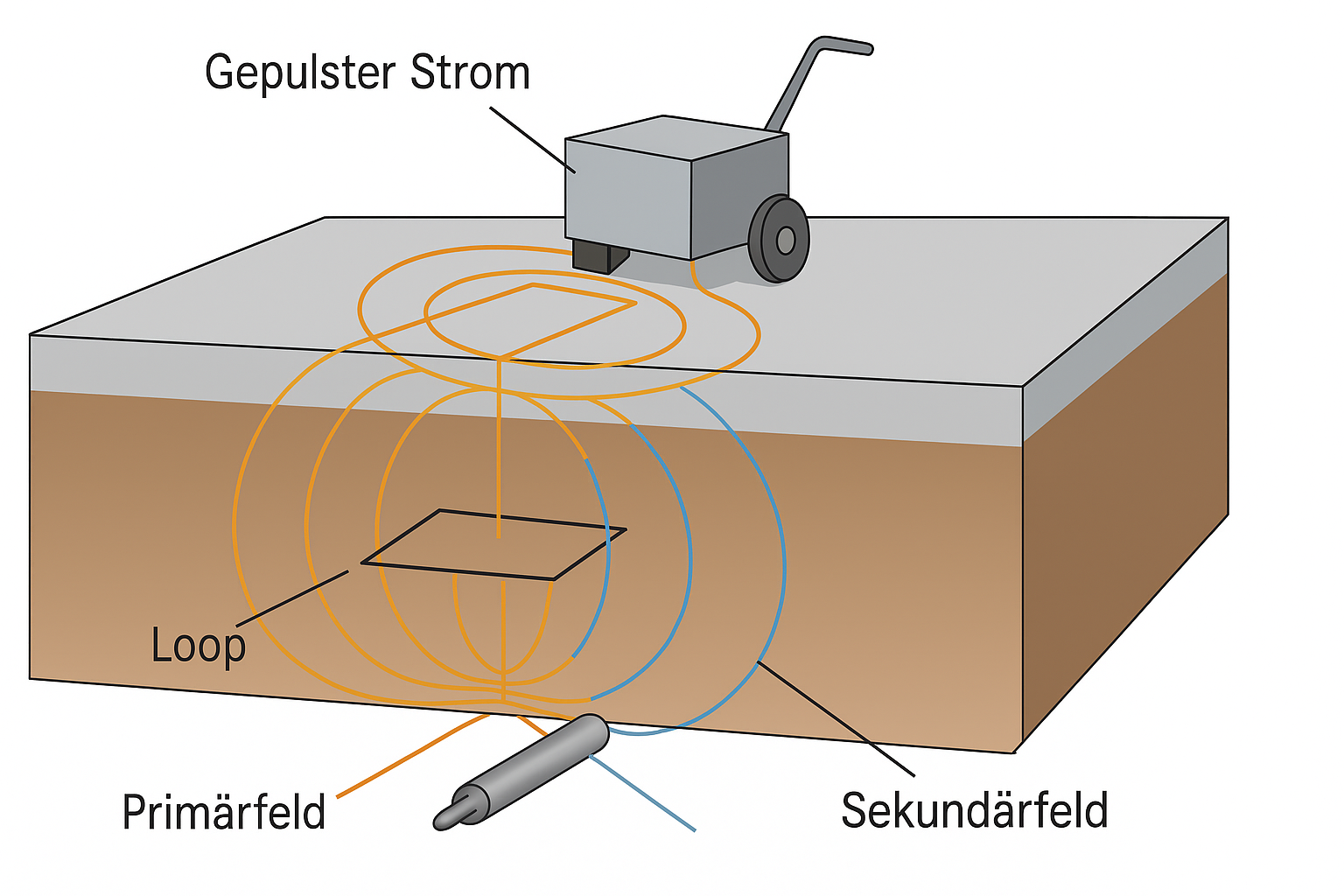
Conductive bodies contribute a secondary signal through induced eddy currents. Several time windows allow more differentiated assessment than a single summed amplitude.
Explore time channels and coil geometry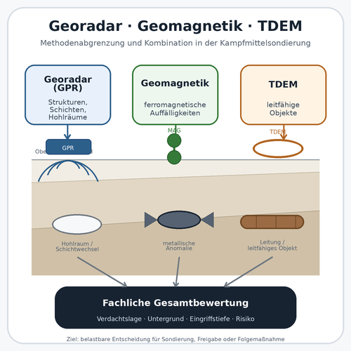
TDEM assesses conductivity, magnetometry ferromagnetic anomalies and ground-penetrating radar structural contrasts. A combination is technically useful only if each dataset addresses a clearly defined uncertainty.
Compare survey methods in contextFerromagnetic anomalies can provide an effective starting basis. TDEM supplements the assessment where conductivity, time channels or a different susceptibility to interference provide additional information.
Assess magnetometry as an addition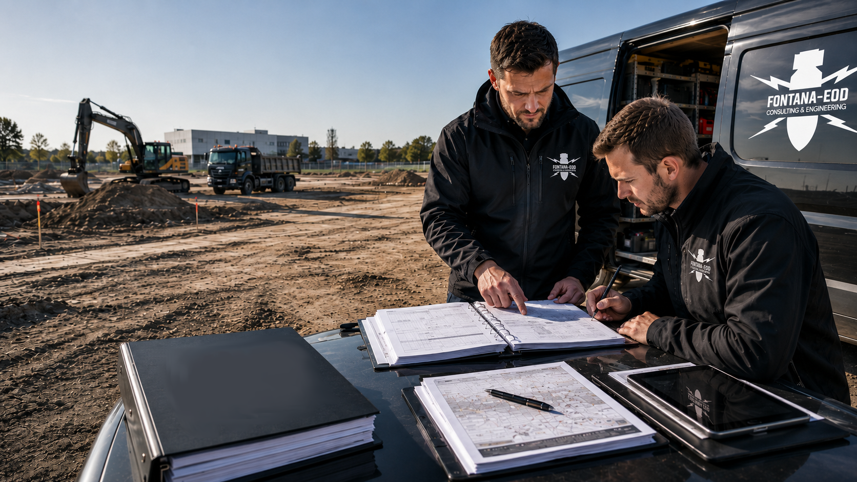
The project file contains not only anomalies but also survey conditions, uninterpretable zones and the technical reasoning for further investigation, exposure or measures during construction.
Document results and follow-up measures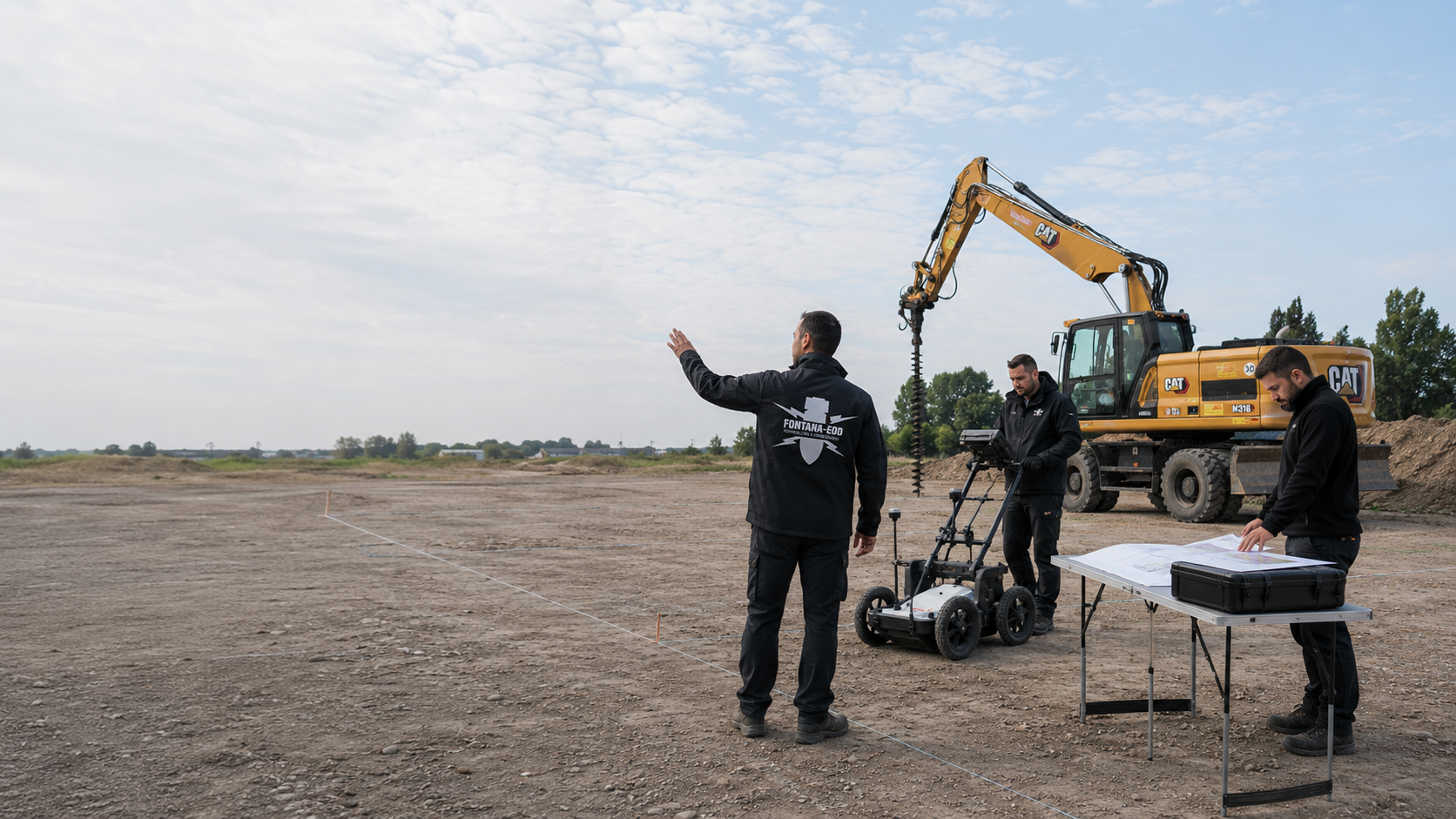
Before the quotation, suitable coil geometry, survey scope and required documents are clarified. This makes clear what service is to be commissioned.
Send project documents for the suitability assessment
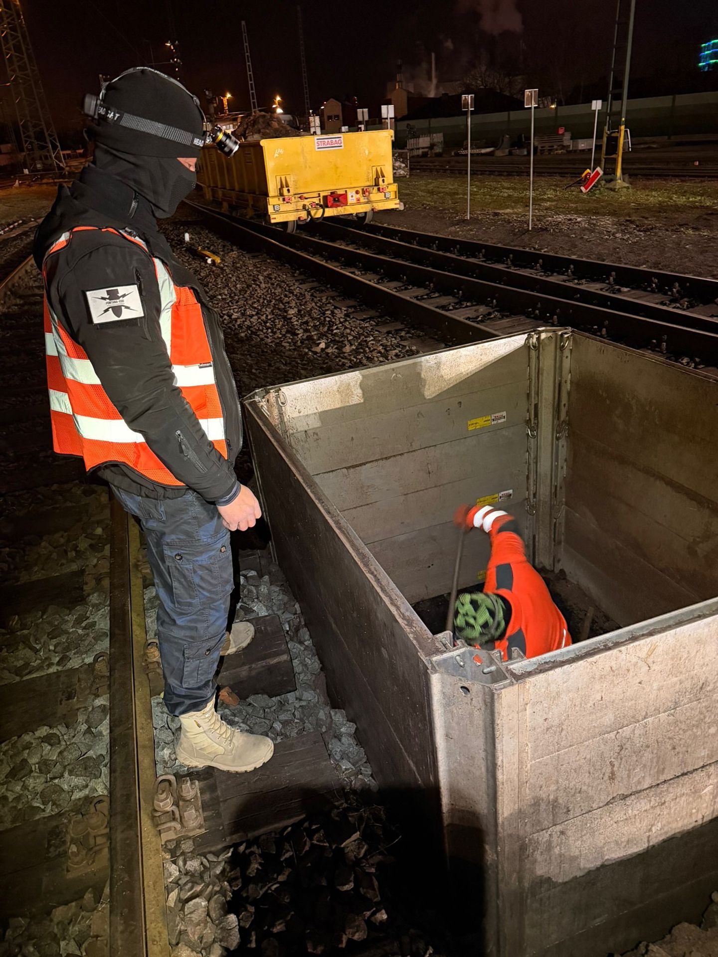
Further work depends on whether an electromagnetic anomaly is explainable, affects the proposed space of the works or lies in a technically restricted area.
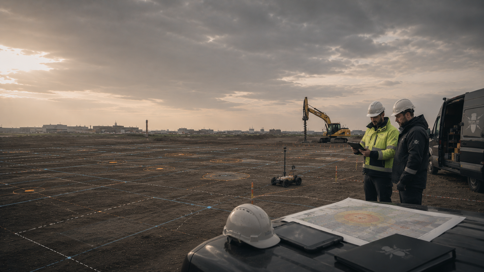
Relate historical assessment, technical investigation, services during construction, clearance and supporting records to the current project phase.
Open the services overviewWeigh up TDEM, magnetometry and radar according to target material, ground, site conditions and desired survey depth.
Check method selectionCheck whether ferromagnetic targets and a sufficiently quiet magnetic field support an additional or primary magnetic survey.
Compare magnetometryInvestigate layers, service zones and structural remains where structural information is needed to interpret the TDEM data.
Assess the use of ground-penetrating radarPrepare boreholes, piles, sheet piles and other individual ground interventions using survey geometry matched to coordinates and design depth.
Plan a deep-ground surveyIntegrate construction areas with persistent metal interference or no survey access into the actual excavation sequence.
Agree specialist excavation supervision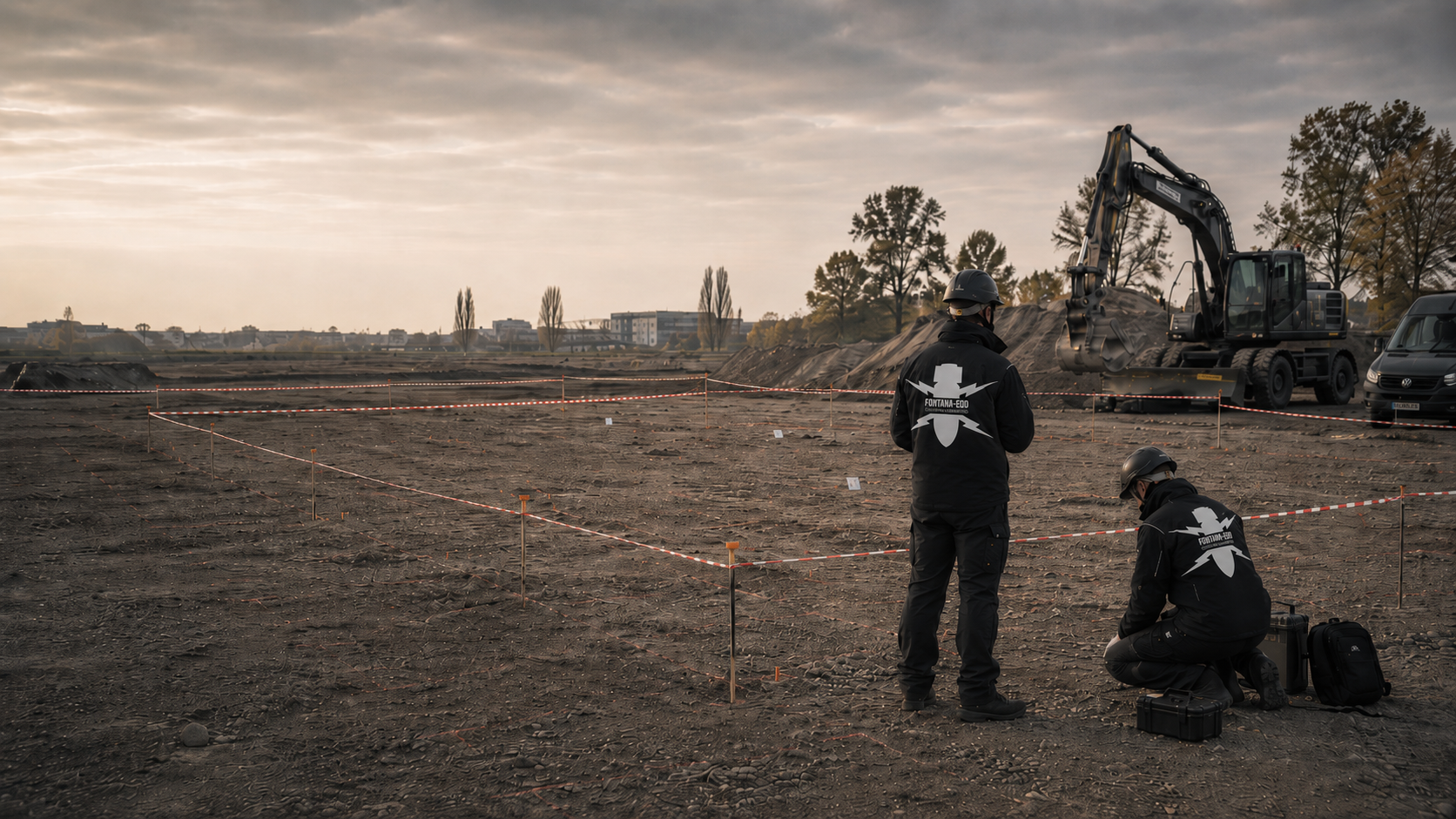
Organise a larger number of anomalies with a defined clearance objective, work limits, quality checks and spatially referenced findings records.
Prepare area clearance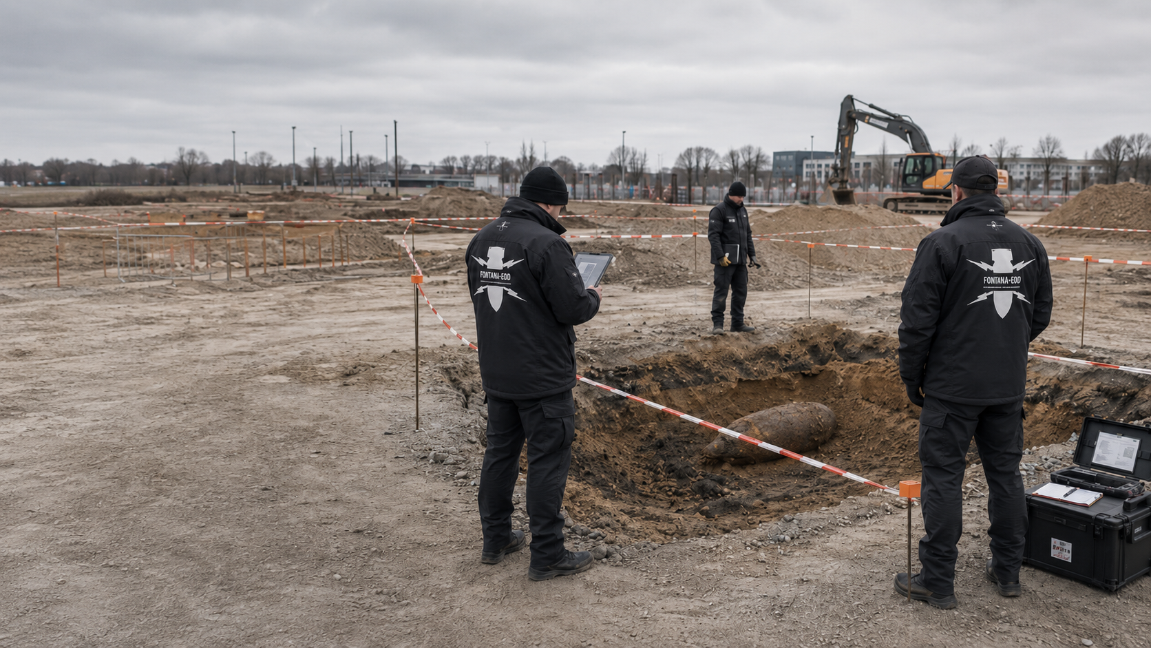
Prepare the handling of an identified ordnance-relevant object within the intended competence and responsibility framework.
Ordnance recovery and responsibilitiesTransfer survey configuration, raw data, target lists, limitations and the follow-up decision into a verifiable project file.
Define the evidence scopeConnect the route, transport surface, industrial site, municipal project or geotechnical investigation with the appropriate working procedures.
Select the application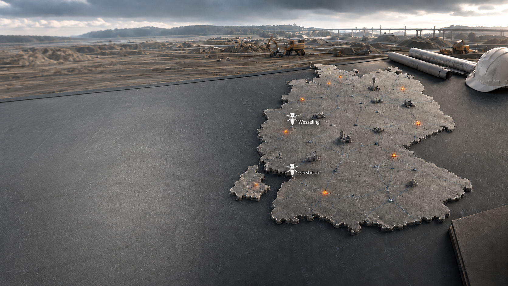
Attach existing official letters for the project location with dates, file references and the associated plan. What matters is whether they address the same area and proposed ground intervention. If additional documents are required, this allows the enquiry to connect with the existing case.
A strong TDEM signal can be caused by a harmless metal object or a known installation. Further work therefore depends on specialist assessment using location, survey conditions and the basis for suspicion. Colour alone determines neither the object type nor how a find is handled.
Understand the survey finding and subsequent decisionBefore target investigation, the anomaly list, plan and report are assigned to the same version. Changed identifiers, relocated points and unresolved survey areas must remain identifiable. Anyone taking over the data therefore receives both the spatial assignment and the technical limitations.
Technical information
The brochure explains time-domain electromagnetic surveying. Technical illustrations make the survey principle, important conditions and interpretation understandable.

TDEM stands for Time Domain Electromagnetics. A transmitter coil generates a primary field. After switch-off, the secondary fields produced by eddy currents in conductive bodies are measured in several time windows. Their spatial distribution and decay behaviour provide indications of conductive anomalies.
The method responds to electrical conductivity and can therefore detect both ferrous and conductive non-ferrous metals. Whether an object is actually detectable depends on its material, size, shape, orientation, depth, coil dimensions and distance from the sensor. Small or deep bodies may remain below the signal strength usable for the project.
TDEM can provide additional information where non-ferromagnetic metal components are relevant or a magnetic survey is limited by a strong background field. This does not mean electromagnetic measurements are free of interference: services, reinforcement, large metal surfaces and technical installations also produce strong TDEM responses.
No. TDEM shows an electromagnetic anomaly, not a certain object identification. Conductive services, scrap, reinforcement, shafts and other installations can cause similar signals. Specialist assessment therefore combines time channels, signal shape, position, the basis for suspicion and known infrastructure; target investigation or exposure follows where necessary.
Problematic areas include zones immediately beside large metal bodies, heavily reinforced surfaces, bundles of services, rails, vehicles, changing sensor heights and ground with strong small-scale conductivity changes. These influences are mapped and may lead to more restricted subarea assessments, additional methods or specialist work during construction.
If a suspicious object is found, stop work. Do not touch or move it. Leave the immediate area, warn others without putting yourself at risk and notify the police — in Germany, call 110; outside Germany, use the local emergency reporting arrangements. KBD or the competent local authorities take responsibility for further hazard response according to the actual find.
At minimum, the survey area, coordinate system, coil configuration, survey height, grid, time channels used, quality checks, survey gaps, interference areas, georeferenced anomalies and specialist follow-up decision are required. Raw and interpreted data should be assigned so that subsequent target points and changes in work status can be traced.
A sound TDEM quotation needs more than the site size and date. The expected range of metals, relevant depth range, achievable sensor height and all installations that can generate their own electromagnetic signal or obstruct coil guidance are decisive.
If surveys already exist, the enquiry should also identify the system used and whether raw data, time channels, driving tracks and positioning data are available. Only then can it be assessed whether a new survey, targeted addition or specialist reassessment is appropriate.
A current site plan with the polygon, route alignment or subareas, the coordinate system used and marked edge zones, slopes, shafts and areas inaccessible to vehicles or people is needed.
For construction in sections, priorities and handover points should already be identifiable so that field acquisition and interpretation fit the programme.
Describe the object sizes and materials underlying the suspicion. State the depth of the later ground intervention. Also indicate whether initial mapping or further investigation of known anomalies is intended.
For individual interventions, coordinates, intervention dimensions and the intended construction method are also needed so that the limits of area-based TDEM conclusions remain clear.
Utility plans and information on reinforcement, fences, rails, vehicles, machinery, transformers, metal building structures and other technical installations are particularly important for the suitability assessment.
Moisture, cohesive ground, made ground, changing surfacing and height differences should also be identified because they can affect early time channels and even guidance of the survey frame.
An initial technical assessment is generally possible where the area plan, basis for suspicion, maximum ground intervention, target object information and current as-built or utility plan are available. For third-party data, please also identify the survey system manufacturer and type, coil arrangement, survey height, available time windows, data format and existing interpretation products.
Survey polygon, route sections, reference points, obstacles and desired field acquisition sequence.
Proposed or existing coils, time channels, track spacing, survey height and positioning method.
Services, reinforcement, installations, vehicles, large metal bodies, surface scrap and changing ground conductivity.
Initial assessment, target prioritisation, tendering, construction sequence, follow-up investigation or final documentation.
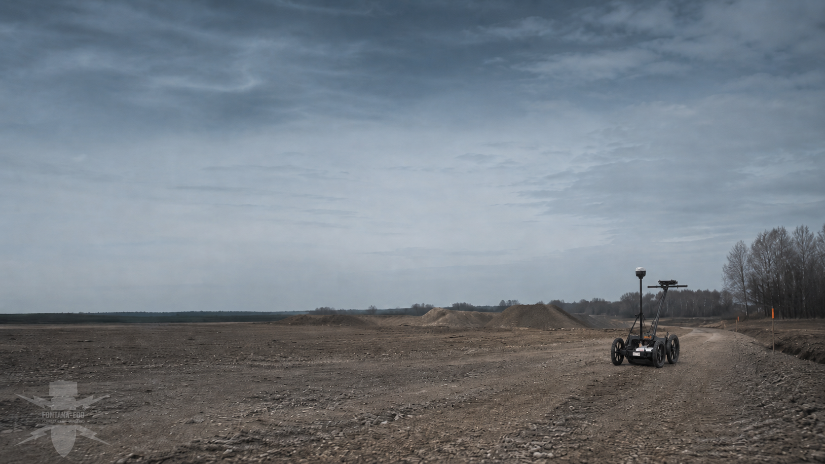
Whether historical aerial photograph analysis, explosive ordnance surveying, surface surveying using GPR, magnetometry or TDEM, deep-ground surveys, downhole surveys, excavation supervision, area clearance or ordnance recovery is needed depends on the location, ground disturbance, depth, ground and existing documents. An early ordnance assessment provides clarity for tendering, programming, occupational safety and construction.
FONTANA-EOD combines its Section 7 SprengG licence, specialists holding Section 20 SprengG certificates of competence, suitable survey and clearance methods, and traceable documentation. Send the site plan, depth of ground disturbance, construction phase and existing documents for an initial technical assessment.


