Project pathway
The quickest route to the right decision.
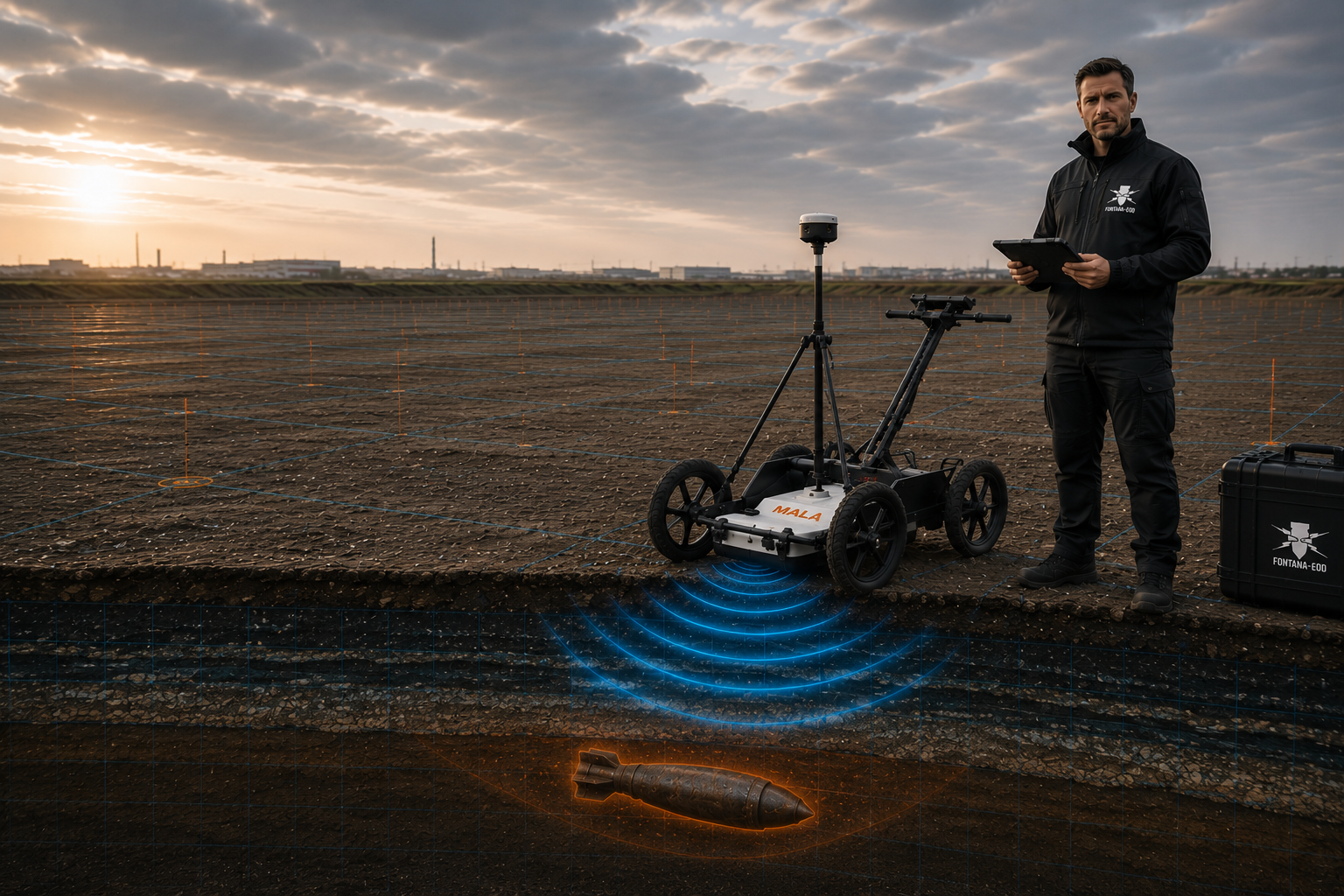
Before ground disturbance, developers, designers and site management need to establish whether the construction site can be investigated adequately from the surface. FONTANA-EOD assesses whether magnetometry, TDEM or GPR suits the target, ground, surfacing, access and interference. Send a site plan, intervention depth and existing suspected-hazard records so survey scope and further investigations can be agreed.
Clarify the surface and access.
Compare magnetometry, TDEM and GPR.
Document anomalies and limitations.
Surface surveys detect geophysical anomalies from the ground surface or the surface of a structure. Suitability of magnetometry, TDEM or GPR depends on the suspected hazard, target, ground and intervention depth. Survey limits and further investigation needs are recorded for the actual construction site.
The scope for “Plattling — track 20, area clearance Plattling / Germany · Lower Bavaria” included surface radar surveying.
Service period: 2026-10
Service areas:Surface surveys: GPR, TDEM and magnetometryMethod used in this project: Ground-penetrating radar
View project details · GPR and limitations · Region: Lower Bavaria
The scope for “Böhne–Bergheim, Edertal — K26 full-depth renewal, Böhne–Bergheim Böhne–Bergheim, Edertal / Germany” included surface radar surveying.
Service period: 2026-10
Service areas:Surface surveys: GPR, TDEM and magnetometryMethod used in this project: Ground-penetrating radar
The scope for “Howald — Howald multimodal interchange, station and track alterations Howald / Luxembourg · Luxembourg” included surface radar surveying.
Service period: 2026-10
Service areas:Surface surveys: GPR, TDEM and magnetometryMethod used in this project: Ground-penetrating radar
View project details · GPR and limitations · Region: Luxembourg
Method selection starts with the investigation objective. The task is not an abstract “search for explosive ordnance”, but a search for particular object types within a defined area and depth envelope under specific conditions. This determines a suitable measurement principle, expected data quality and supplementary measures for uninterpretable areas.
Historical aerial photograph analysis defines suspected hazards before technical survey planning. Image quality, temporal coverage and available sources limit its conclusions; suspect areas and data gaps are described spatially in the report. If technical investigation identifies further work, target investigation and, where appropriate, area clearance are planned according to the findings. The clearance objective, access and working conditions determine their scope; findings and clearance records document areas actually worked and handovers.
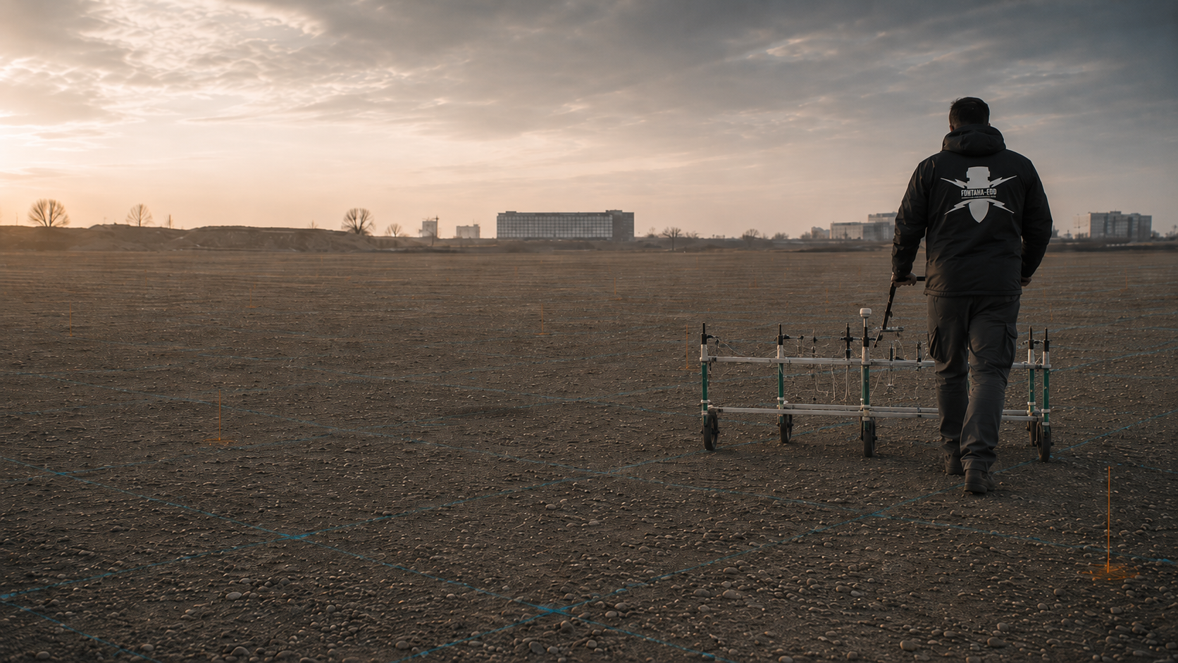
Magnetometry detects changes in the Earth’s natural magnetic field, particularly those caused by iron-bearing or ferromagnetic objects. It often suits open, adequately accessible sites where survey lines can be acquired with consistent sensor movement and traceable georeferencing. Depending on area and terrain, handheld probes, multichannel carts or vehicle-mounted systems may be considered.
Steel components, vehicles, fences, rails, reinforcement, utilities, scrap and magnetically anomalous fill may mask the survey image. Suitability therefore depends on the target, required detection depth, sensor distance, interference and achievable data quality, not area size alone.
Survey lines, sensor movement and positioning are linked to the anomaly map. Documentation distinguishes interpretable survey areas, magnetic interference zones and unrecorded margins. Assessed anomalies can then be relocated for further field investigation.
Assess magnetometry for the site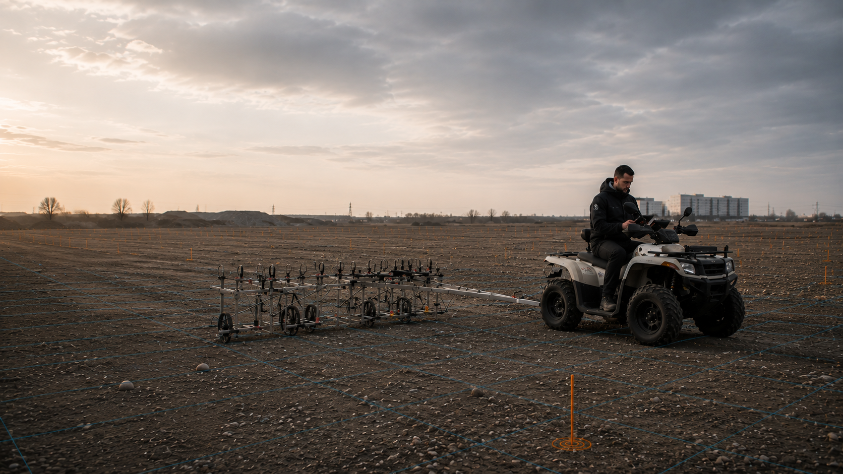
TDEM is an active electromagnetic method. A time-varying primary field excites conductive objects in the ground; resulting secondary signals are measured within defined time windows. The method can respond to ferrous and non-ferrous metals and complement magnetometry for suitable tasks.
Coil size, survey height, object size and position, ground, utilities and other conductive structures affect detection. TDEM is therefore neither generally interference-free nor automatically deeper-reaching. The configuration is tailored to expected targets and the required assessment envelope.
The TDEM record states coil configuration, survey height, time windows and spatial reference. Interpretation assigns anomalous secondary signals to surveyed areas and marks zones where conductive infrastructure limits object assessment.
Assess TDEM for the site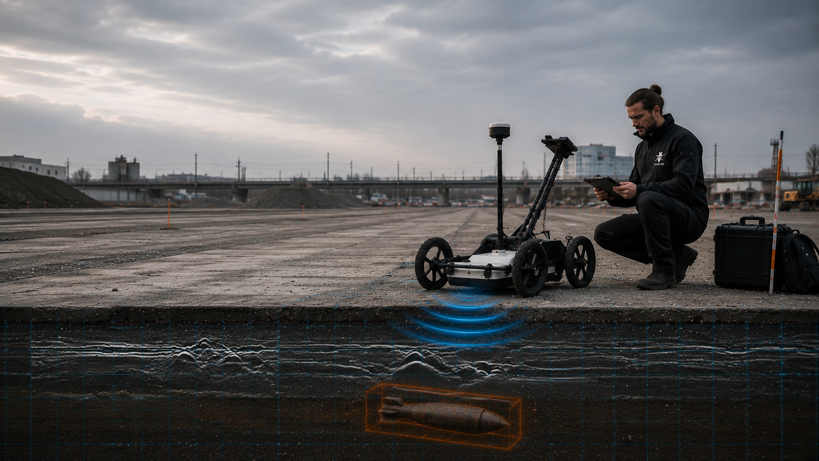
GPR transmits electromagnetic pulses into the ground and records reflections at material contrasts, layer boundaries and objects. In suitable conditions, it can indicate utilities, fill, foundations, voids, buried installations and other structural anomalies.
The conclusions supported depend particularly on moisture, electrical conductivity, clay content, ground variability, surface construction and antenna configuration. GPR does not identify a suspect object from a single radar image alone. Its value lies in specialist interpretation of structural information and supplementing other methods.
Radar profiles are referenced to the site plan with survey direction, positioning and antenna configuration. The report identifies assessed reflections, the usable depth reference and areas with inadequate penetration or ambiguous structural information.
Understand the technical role of GPR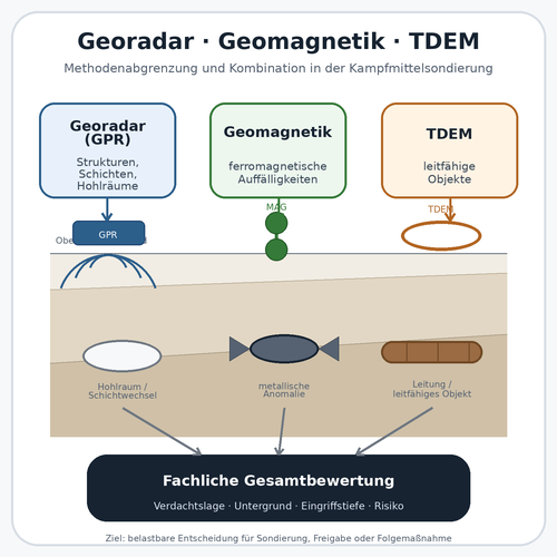
A combination is useful where several object types are expected, one method is restricted by survey conditions or additional structural information is needed for assessment. Methods are not merely run alongside one another; they address a shared project question in a common coordinate system.
The combined assessment must show which method covers each area and physical property. Contradictory or non-coincident findings are not mathematically “smoothed out”; they are assessed by specialists and, where necessary, clarified through trial measurements, target investigation or supplementary surveying.
A shared site plan shows which methods and data support assessment of each subarea. Differing findings, investigation limits and unresolved spatial assignments remain visible so supplementary investigation can be planned selectively.
Prepare the investigation design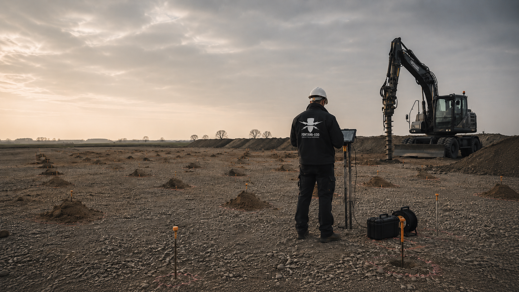
If the proposed intervention extends below the interpretable range of an area-wide survey, the actual working envelope must be assessed separately. This particularly concerns boreholes, piles, sheet piles, anchors, masts and other point or linear interventions at depth.
Surface surveys may provide important preliminary information, but do not replace depth-specific investigation geometry. Borehole locations, target depth, diameter, installation method, safety distances and interference underpin a separate deep-ground or downhole survey.
Point-specific records link coordinates, drilling and survey geometry, target depth, interference and results. Designers and contractors can then check whether the later intervention fits the investigated envelope. Relocated points or changed depths require another comparison.
Investigate the depth envelope separately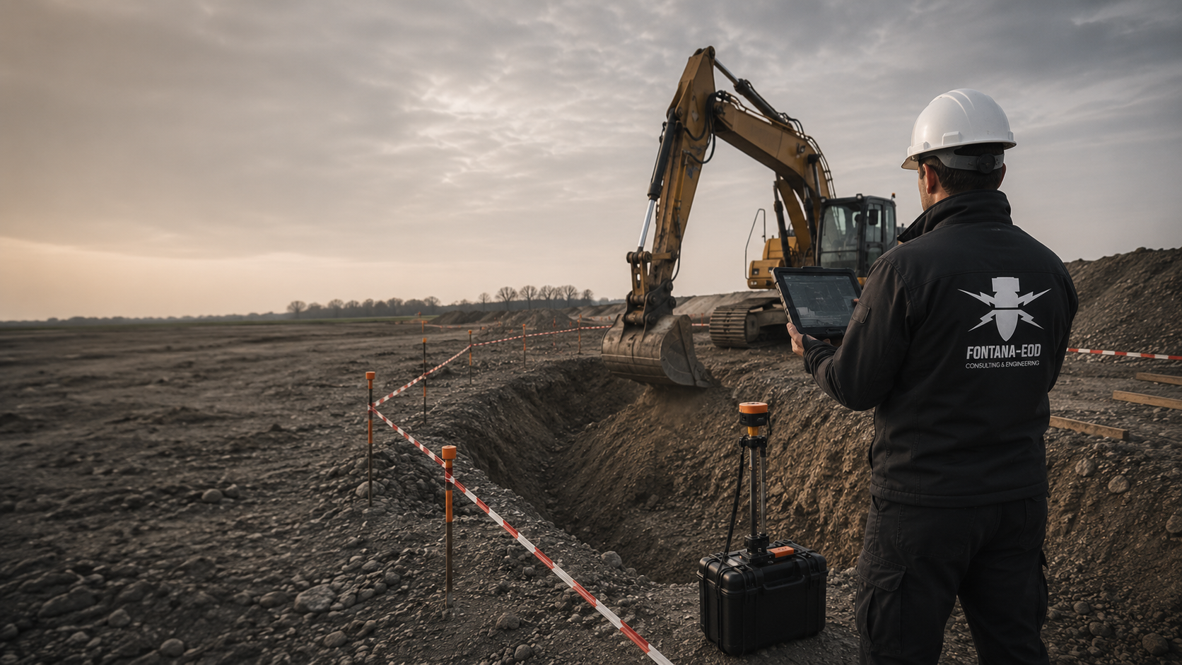
At existing sites, in fill, beside extensive utilities or reinforcement, and in inaccessible subareas, equivalent survey quality cannot be assumed throughout. These zones are defined spatially and compared with the proposed excavation or working method.
Explosive ordnance surveying during construction is an option only where it can adequately cover the actual working envelope. Technical surveying and a specialist decision precede each stage of soil removal. Excavation proceeds in layers under additional visual supervision, repeating to the proposed formation level. Work organisation and hold points are defined before work begins.
Layer and section records link technical surveying, specialist decisions and soil removal to the actual working envelope. Interruptions, changed construction conditions and uninvestigated zones are documented so site management can locate the next step spatially.
Understand excavation supervision requirementsBefore the first survey pass, we define which objects should be detected within which area and depth envelope. We compare the basis for suspicion and proposed ground intervention with the surface, ground and known interference.
Historical aerial photographs, archive information, former military or industrial uses, known finds and existing statements determine which object types and patterns of ordnance presence are plausible. General suspicion for a property is insufficient where only a subarea or particular intervention is to be investigated.
The basis for suspicion is referenced to the site plan, construction site, route or section. This establishes which areas need complete, section-based or point-specific work and whether a technical surface survey is the next appropriate step.
The survey task depends on whether larger ferromagnetic objects, smaller munitions, conductive non-ferrous metals, buried infrastructure or structural ground changes are relevant. Object size, shape, position and material properties affect which measurement principle can produce a usable signal.
The proposed intervention matters equally. A utility trench, area-wide topsoil removal, demolition, breaking out a road or foundation works affect different depths and working envelopes. The investigation area must cover this geometry rather than follow property boundaries alone.
Open ground, vegetation, ballast, paving, asphalt, concrete, track areas and indoor spaces place different demands on sensor movement, survey height and line positioning. Uneven ground, vegetation, obstacles and changing surfaces may affect coverage and comparability between lines.
Before execution, establish whether the site can be accessed on foot or by vehicle, which areas can be made accessible by removing obstacles or cutting vegetation, and where deviations from the planned grid are unavoidable. Inaccessible zones are identified clearly in the survey plan and subsequent report.
Utilities, rails, fences, sheet piles, reinforced concrete, vehicles, containers, scrap and former structures can generate magnetic or electromagnetic signals. Their location and extent determine whether a method needs local restrictions, a different configuration or supplementation by another measurement principle.
As-built plans are not always sufficient because their positional accuracy and currency may vary. Known interfering objects are therefore checked against field conditions. Subsequent interpretation distinguishes measurable anomalies from areas where interference prevents reliable individual-object assessment.
Line spacing, sensor arrangement, survey height, acquisition speed, coordinate system and positioning method follow the target and required conclusions. A high point count alone does not guarantee quality if survey lines are inconsistent, areas are omitted or coordinates cannot be assigned reliably.
Suitable quality checks are defined beforehand. These may include trial surveys, control lines, plausibility checks, coverage checks and comparison with known reference objects or interference sources. Quality control must be traceable in the report.
Before work begins, establish how the result will be used: design, tendering, selection of further surveys, target investigation, excavation supervision or documentation of a defined working area. The report addresses that decision and must not exceed the work scope.
The result may show that an area is technically interpretable, individual anomalies require further investigation or particular zones remain unresolved because of interference, depth or access. A technically suitable next step is identified for each category.
For technically reliable and economically comparable planning, the survey area, target, intervention, ground, interference and documentation objective must be defined clearly in the enquiry and specification or clarified jointly before work begins.
Tender specifications should describe the required conclusions functionally, with minimum requirements for coverage, georeferencing, quality checks and data handover. Specifying equipment alone without targets and constraints may produce technically different, incomparable quotations. Treatment of areas affected by vegetation, buildings, utilities or interference must also be defined. Such zones need a separate method, later exposure or documented investigation during construction.
Preparation also includes safe access, traffic and operating conditions, responsible personnel and arrangements for reporting finds. Gaps and poor-quality data are documented spatially. The depth that can actually be interpreted, considered against the proposed intervention, determines the conclusions the report can support.
Area size, boundaries, construction sections, route width, exclusions and overlaps are shown on an unambiguous site plan. The area actually requiring investigation is decisive, not property size alone.
Expected object types, relevant depth range and subsequent project decision must be identified. Only then can the sensor, survey grid, interpretation and quality checks be justified technically.
Vegetation, ballast, paving, asphalt, concrete, tracks, slopes, wet conditions and uneven ground affect sensor movement and access. Changing surfaces are described by section.
Geology, fill, moisture, clay content, rubble, layer changes and groundwater may alter signal propagation or background noise. Existing geotechnical and contaminated-land records are therefore relevant.
Utilities, reinforcement, fences, sheet piles, rails, vehicles, machinery, containers and metal-bearing fill are mapped wherever possible. Mobile sources of interference must be removed from the working area during surveying.
Access routes, bearing capacity, slopes, vegetation, operations, traffic, closure periods and simultaneous trades determine the survey systems that can be used and areas with restricted investigation.
The coordinate system, positional accuracy, GNSS reception, obstructions and existing control points must suit the required relocation accuracy. Alternative positioning methods are needed where reception is obstructed.
Report format, site plans, anomaly schedules, digital geodata, coordinates, raw and processed data, and required file formats are agreed beforehand so results can be used in design and the project file.
The report must show what was investigated and how interpretation was performed. This includes the survey commission, areas recorded, equipment and method parameters, data quality, findings and remaining limitations.
Acceptance requires more than a map or report. The service becomes verifiable when the agreed investigation envelope is fully referenced, data quality is assessed against the survey objective and each limitation has a specific follow-up measure. Before work begins, clients should define required digital and paper records, agree whether raw data is supplied and specify coordinate and file formats. It should also be clear how the anomaly locations can be found again on site. For phased construction, arrangements must additionally cover interim records, areas becoming accessible later and updates to changed project geometry.
If surveying is followed by exposure, area clearance or recovery, the resulting findings and clearance records are linked to the preceding survey documentation. The record then identifies the stage actually completed and its limitations. Survey documentation alone does not claim that these follow-up works have already been completed.
The report identifies the project, client, investigation objective, expected object types, relevant depth range and area worked. The site plan, coordinate system and boundaries must agree with the enquiry and execution.
The measurement principle, sensor system, channel count, survey height, line spacing, acquisition speed, positioning and special configurations are documented. Deviations from the design must explain their causes and effects on the conclusions.
Survey lines, omitted zones, obstacles, interference, surface changes, weather or operating conditions and control measurements are recorded traceably. This shows which areas were actually investigated under comparable conditions.
Raw data, filtering, corrections, interpolation and further processing are described so interpretation can be reviewed technically. An attractive map does not replace documentation of the underlying data quality.
Relevant anomalies are shown with coordinates, signal characteristics, priorities and specialist assessment. The schedule distinguishes individual anomalies that can be investigated, area-wide interference and zones where reliable object separation is impossible.
The conclusion identifies the project question answered, areas and depths covered and remaining limitations. Suitable follow-up measures, such as target investigation, deep-ground surveying or excavation supervision, are proposed for unresolved anomalies and uninterpretable zones.
The basis for suspicion, construction phase and site conditions determine the work sequence and survey design. Acquisition, interpretation and handover are tailored to the proposed ground intervention.
The proposed intervention, work area, target, required depth range and decision are described. This defines what the survey must establish.
Site plans, aerial photograph assessments, authority records, as-built plans, utility data and earlier investigations are checked for spatial relevance, currentness and unresolved questions.
The surface, vegetation, access, obstacles, utilities, reinforcement, vehicles, machinery and other interference are compared with the proposed survey design.
Magnetometry, TDEM, GPR or a combination is selected according to the target and survey environment. Sensor arrangement, line spacing, positioning and control measurements are defined.
The area is recorded along the proposed grid. Deviations, interference, inaccessible zones and unusual field conditions are recorded immediately.
Raw data is checked, georeferenced and interpreted by specialists. Anomalies are compared with interference sources, ground information and historical suspicion.
Relevant individual anomalies, area-wide interference and uninterpretable areas are shown separately. Further investigation needs are identified for each category.
Reports, location and anomaly plans, findings schedules, survey-data information and follow-up decisions are provided for design, tendering, site management or the project file.
A coloured survey-area visualisation does not establish that every part of the proposed working envelope was investigated. The spatial reference, areas actually recorded and interpretation limits are decisive.
Survey lines, vehicle tracks or individual points are compared with the investigation plan. Obstacles, inaccessible margins and areas with inadequate signal quality remain separately identifiable. A graphically continuous area must not conceal these differences.
The report must identify the ground or structural surface to which depth refers and how it was determined. Particularly for GPR, conversion from travel time to depth depends on the assumed propagation velocity. Later ground-level changes must therefore be considered when comparing results with construction plans.
For larger or differing subareas, trial surveys and early results can inform subsequent planning. Section identifiers, parameters and spatial references must agree. This distinguishes whether a new finding comes from another subarea, another method or changed survey conditions.
Selection is not based on a general ranking. Each method measures a particular physical property, has typical interference susceptibility and supports a limited type of conclusion. The appropriate combination follows the project question.
Project decisions must also distinguish whether a method should provide an area-wide overview, target prioritisation, supplementary structural information or a depth investigation. A method can perform well under suitable conditions yet remain unsuitable for another object type or survey environment. Assessment therefore relies on achieved signal quality rather than general range or accuracy claims.
The assessment establishes spatial grounds for suspicion from historical images and other available records. It helps define targets, affected subareas and the technical follow-up question.
Image quality, temporal coverage and available sources limit the conclusions. Suspect areas and data gaps are documented; an appropriate technical investigation establishes an object’s present-day location.
Technical contribution: Area-wide detection of ferromagnetic anomalies with clear spatial references on suitable sites with sufficiently little interference.
Principal limitation: Magnetic interference from steel, reinforcement, rails, vehicles or scrap may substantially restrict separation of individual objects.
Technical contribution: Active detection of conductive metal objects and additional differentiation where magnetic measurements alone are insufficient.
Principal limitation: Utilities, extensive metal structures, coil geometry, object size and ground affect the signal and achievable conclusions.
Technical contribution: Visual structural information about layers, buried installations, utilities, fill and objects under suitable electromagnetic ground conditions.
Principal limitation: Wet, clay-rich or highly conductive ground and heterogeneous fill may substantially reduce penetration depth and interpretability.
Technical contribution: Links different physical information and may support more differentiated assessment of interference zones or ambiguous findings.
Principal limitation: More data does not replace a common project question. Survey areas, coordinates, depth references and interpretation must be methodologically compatible.
Technical contribution: Investigates defined point or linear ground interventions at depth that a near-surface area survey does not cover adequately.
Principal limitation: Conclusions apply to the defined drilling and survey geometry, not automatically to the entire area between investigation positions.
Technical contribution: Where technically suitable, remaining working envelopes are surveyed and assessed before each stage of soil removal. Following the specialist decision, excavation proceeds in layers with additional visual supervision. The sequence repeats layer by layer to the proposed formation level.
Principal limitation: Does not replace prior planning and provides records only for the working areas and excavation layers actually supervised.
Use, construction methods and operating conditions affect access, data quality and potential follow-up measures. An open development site differs from a track area, industrial facility or urban utility trench. These constraints therefore inform method selection and preparation from the outset.
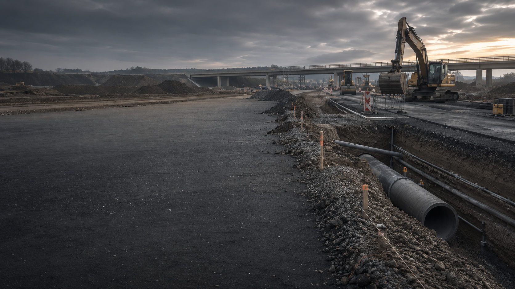
Carriageways, roadside areas, sewer routes and excavations combine changing surfaces, utilities and excavation depths. Survey sections are planned to keep subsequent working areas and construction phases clearly referenced.
Surveys for road and civil engineering works
Rails, overhead lines, cables, signalling and restricted working windows shape survey conditions. Magnetic interference, access and linear chainage must be considered together in survey and documentation design.
Surveys along railway routes
Cable and pipeline routes, mast locations, substations, wind farms and solar parks require section-specific assessment. Crossings, flush drilling, assembly areas and existing utilities affect methods and working width.
Assess utility and energy project requirements
Existing foundations, utility networks, production facilities, scrap and heterogeneous fill create complex interference. Subareas often need separate assessment and a combination of methods or measures during construction.
Investigate industrial sites
Public-sector clients need clear specifications, comparable quotations and verifiable results. Area references, data formats, quality requirements and follow-up measures should be defined during procurement.
Prepare a municipal project
New developments and neighbourhoods combine large sites with later individual construction plots, roads, utilities and foundations. Surveys are planned by construction section. Documentation records the intervention envelope investigated in each case.
Housing and site development
Operational facilities, protected areas, restricted access and dense technical infrastructure require coordinated survey and safety planning. Interference and operating conditions inform coverage and scheduling beforehand.
Understand sector requirements
Sampling, dynamic core sampling, wells, ground investigations and remediation enter the ground at individual points or over an area. Explosive ordnance, contaminated-land and geotechnical questions are assessed separately with coordinated field sequences.
Explosive ordnance assessment for environmental and geotechnical workFor risk assessment and project communication, a traceable basis for suspicion, defined work areas, documented survey limits and clear follow-up decisions matter more than blanket statements of safety.
Understand sector requirementsThe appropriate follow-up service depends on the conclusions still needed for your ground intervention, not solely on a striking colour in a survey plan.
Where the basis for suspicion is unresolved, existing historical records and the proposed intervention must first be considered together. This helps focus technical investigation on the relevant question.
If a borehole location, piled foundation or shoring alignment falls outside the reliable investigation envelope, supplementary investigation is assessed for that precise space. A surface survey cannot be extended by simply increasing a depth figure in the report.
Where survey limitations remain, measures during construction may be an option. Before excavation, their suitability for the actual task must be assessed against the suspected hazard, working method and achievable control.
Before work begins, responsibilities must be clear for providing the site, planning and conducting surveys, interpreting data and receiving results. Those responsible for occupational safety and action on a possible find are also identified.
Defines the project objective, work area, timing, required conclusions and interfaces. Provides existing records and ensures unresolved subareas and follow-up measures are considered in design and construction.
Translate the project into construction sites, routes, intervention depths and specifications. Coordinate the documentation objective with other design services and assess whether survey results support the proposed decision.
Arrange access, site preparation, traffic protection and agreed working conditions. Mobile interference, simultaneous trades and construction-sequence changes are communicated in good time.
Assesses suspected-hazard and project information, develops the survey design, performs the agreed surface survey and evaluates data, anomalies, interference zones and methodological limitations against the investigation objective.
Survey data is georeferenced, processed and interpreted by competent personnel. Explosive ordnance decisions are made within the appropriate qualification and responsibility framework and linked to the project question.
Depending on the federal state and circumstances, competent authorities handle hazard response, finds or decisions on further measures. Private specialist services provide spatially referenced project and investigation results for these tasks.
The responsibilities of KBD, KMBD or KRD and local public-order authorities vary by project location. Building control may also be involved. Existing correspondence is forwarded with its date and spatial reference; specific decision-making and reporting arrangements are clarified locally.
A surface survey forms part of a project-specific investigation and decision process. Applicable legal and technical requirements depend on the commission, expected ordnance type, subsequent target investigation and regional responsibilities.
Section 7 SprengG regulates the commercial licence for activities requiring authorisation; section 20 concerns the certificate of competence for responsible persons. A geophysical survey may also be intended to search for ammunition; such searching is expressly covered by section 1b(1), no. 3(d) SprengG. Purpose and actual activity scope are decisive, not the instrument’s name alone. The company, responsible personnel and required authorisations must match. The 1. SprengV and, where relevant to the actual activity, DGUV Rule 113-003 may also need consideration.
DGUV Information 201-027 supports clients, designers and specialist contractors with risk assessment and protective measures for explosive ordnance clearance work. It places investigation, planning, clearance concepts, working methods, responsibilities and documentation within a connected sequence.
For federal properties, the BFR KMR construction guidelines structure the planning and execution of investigation, assessment and clearance. Appendices address magnetometry, electromagnetics, GPR, trial surveys, geophysical documentation and technical specifications. Other projects may use this as technical guidance without replacing state-specific requirements or the actual specification.
The investigation objective, work area, expected object types, intervention depth and subsequent decision are defined clearly before procurement.
Working methods, expected hazards, area, equipment, personnel, traffic routes, interference and reporting arrangements are assessed for the deployment.
Specialist competence, responsibility and any required explosives licence or certificate of competence must suit the activities actually commissioned.
Survey design, coverage, data quality, findings, limitations and follow-up decisions are documented verifiably.
The area, target, survey method or functional service requirement, quality checks, data formats, treatment of interference zones and required records are described to enable meaningful technical comparison of quotations.
Working areas, responsible personnel, briefings, access arrangements, mobile interference, traffic and operating conditions, and responses to unexpected anomalies must be known on site.
If suspected explosive ordnance is found, stop work immediately. Do not touch or move the object. Leave the danger area, warn others without putting yourself at risk and notify the police immediately — in Germany, call 110. Follow the emergency services’ instructions.
Documentation covers the investigated area, survey data, findings and limitations. Site plans and reports must allow clients and site management to relate results to the proposed intervention.
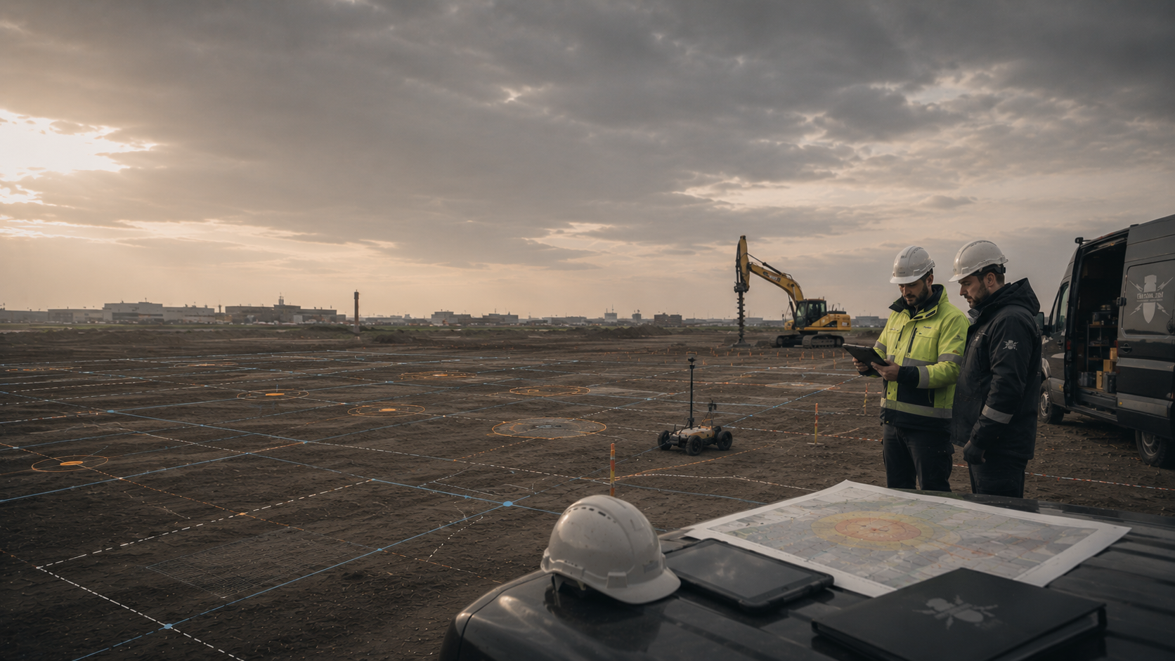
Shows survey boundaries, survey tracks, overlaps, obstacles, inaccessible areas and their relationship to the site, route or construction section.
Document survey coverage clearly
Combines measurements, map references, signal strength, interference zones and prioritised anomalies into a spatially verifiable basis for assessment.
Understand magnetometry and anomaly assessment
Documents the survey framework, time windows, acquisition conditions, anomalous secondary signals and their specialist distinction from known conductive sources of interference.
Assess TDEM data
Shows reflections, changes in strata, utilities, installations and other structures, and describes which areas can be interpreted and where interpretation is restricted.
Understand radar profiles and structures
Connects historical findings, project boundaries, the proposed ground disturbance and the technical survey area, so that interpretation and subsequent decisions use the same spatial basis.
Review historical evidence of suspected ordnance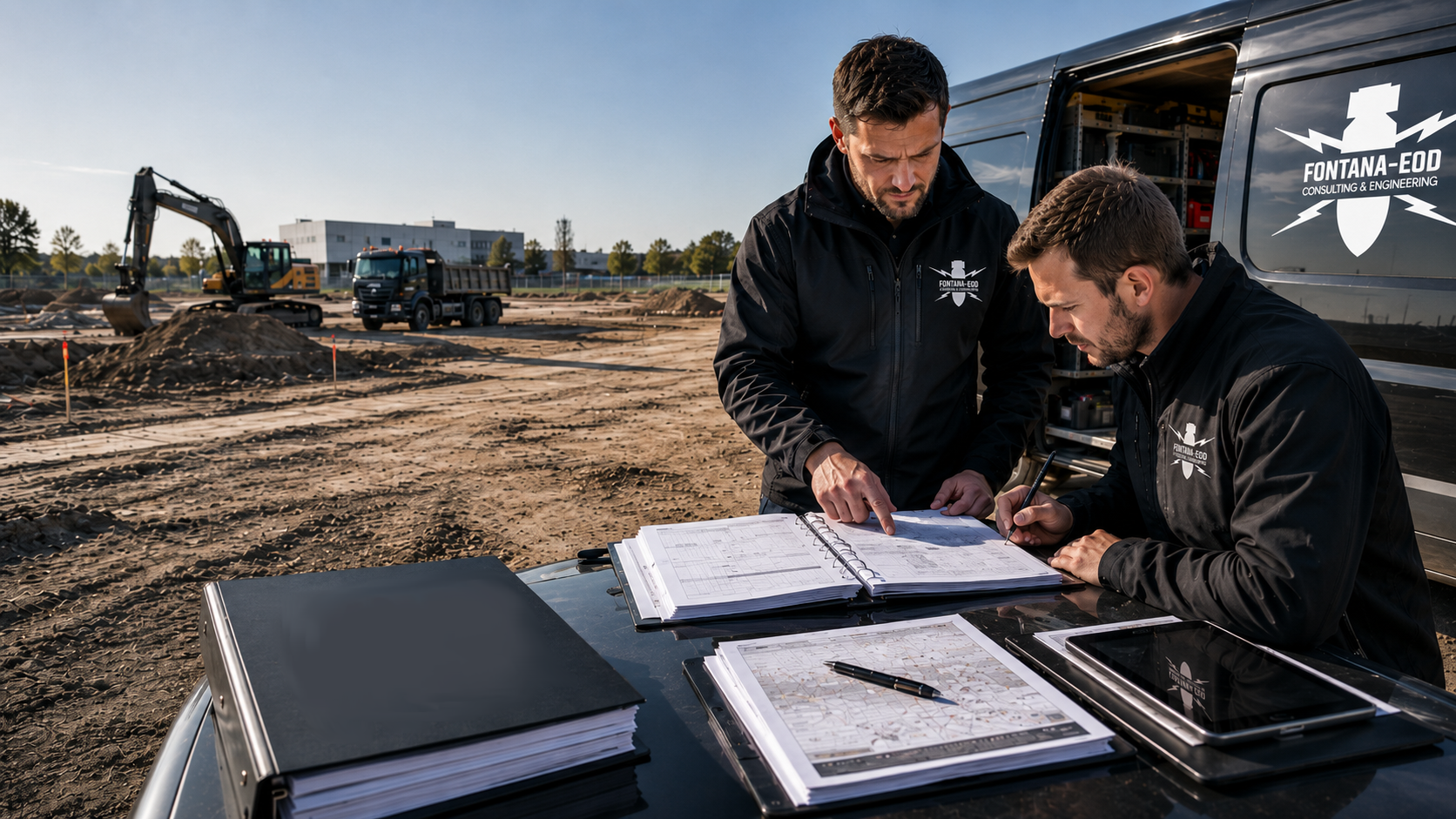
Describes the task, method, area coverage, data quality, anomalies, interference zones, unresolved areas and technically appropriate further work.
Document findings and next steps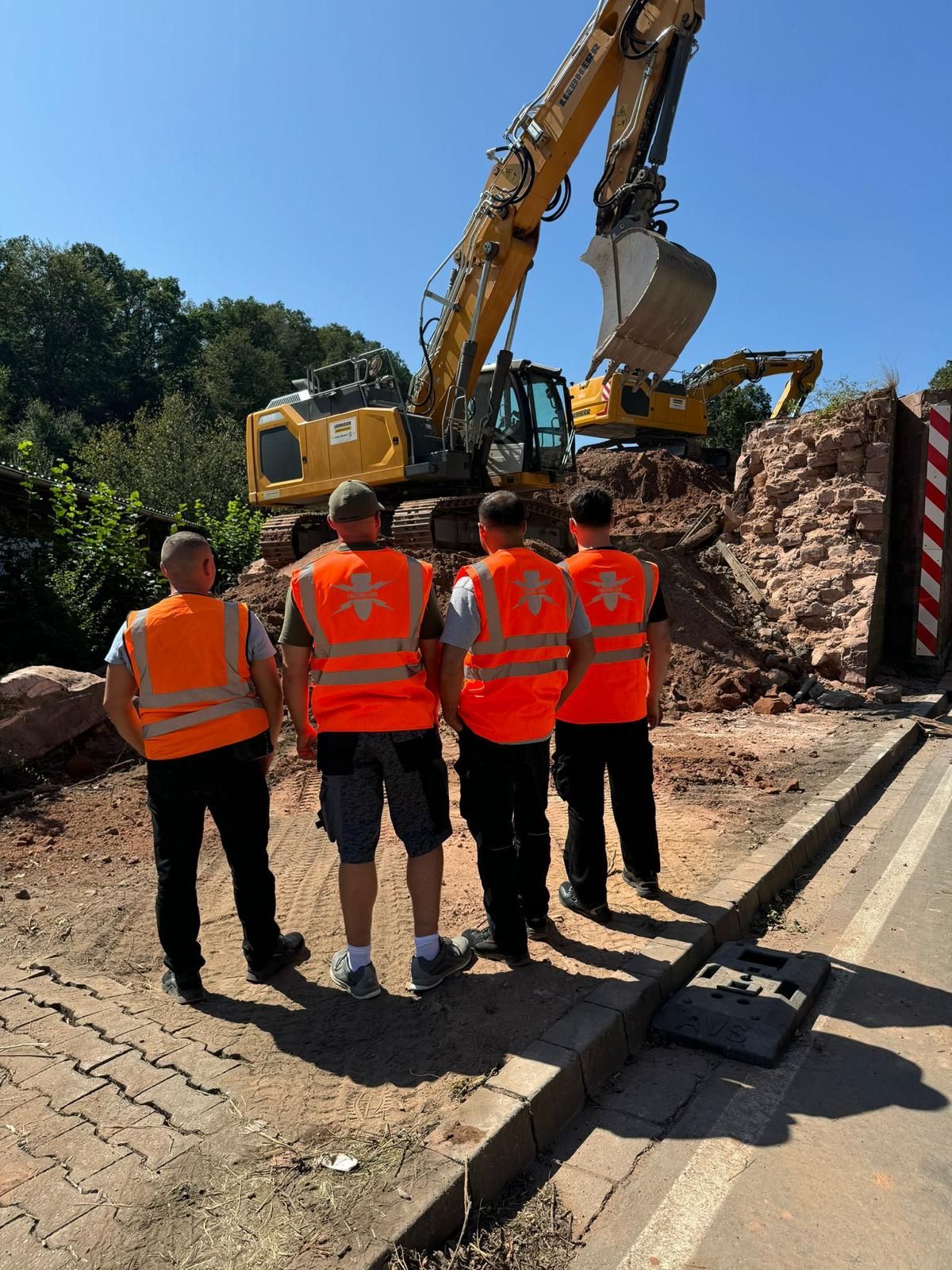
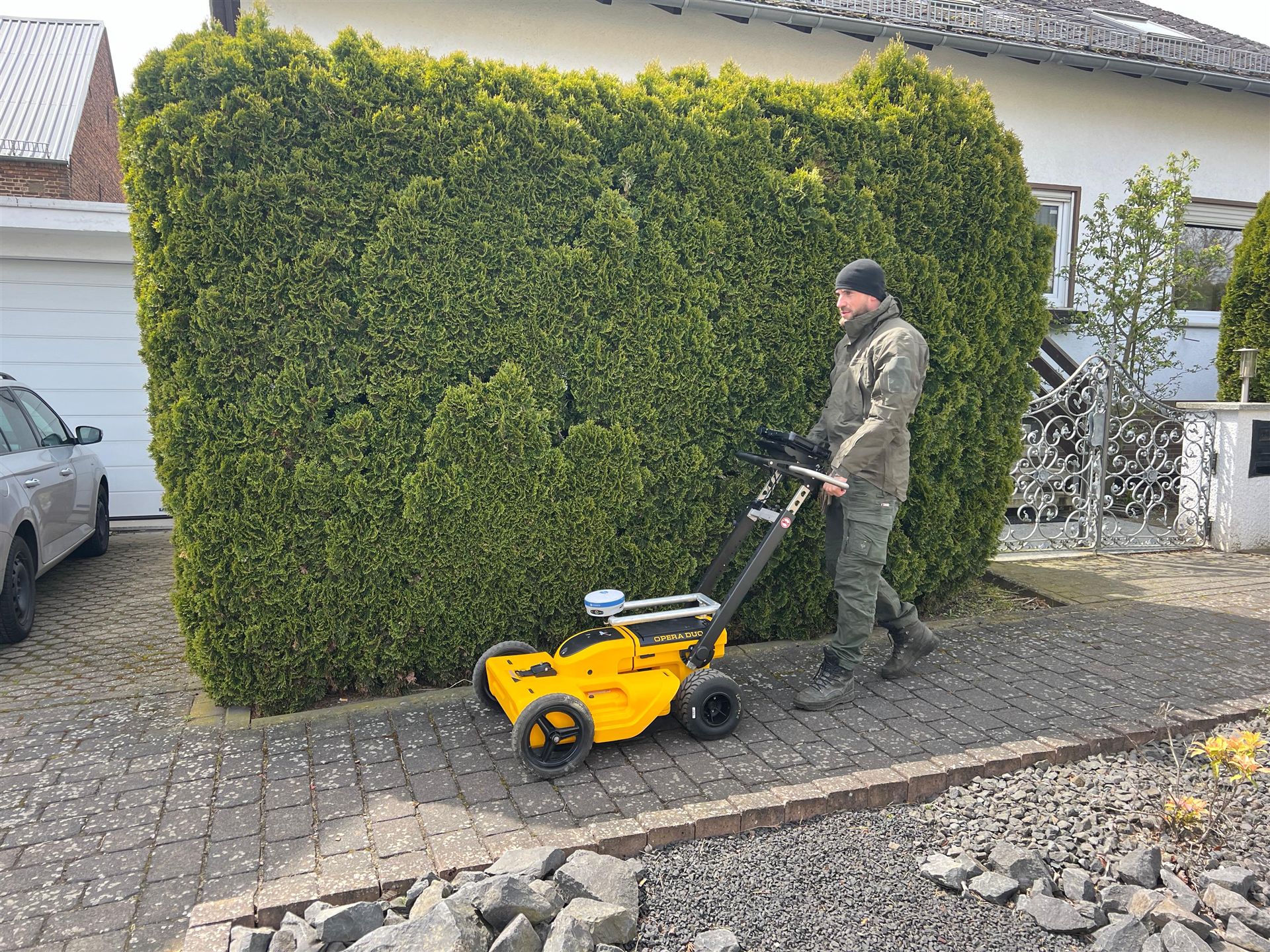
Depending on the findings, further investigation using a particular method, a depth-specific assessment, supervision during construction or preparations for clearance and verification may be required. The next step depends on the unresolved project question, the ground disturbance and the documented survey limits.
Relate the measurement principle, multichannel acquisition, ferromagnetic targets, interference fields and interpretation to the project area.
Magnetometry: applications and limitationsAssess coil systems, conductive targets, time windows, survey conditions and limitations in relation to the project question.
TDEM: applications and limitationsAssess radar profiles, subsurface structures, antenna selection, dependence on ground conditions and interpretation.
Ground-penetrating radar (GPR): applications and limitationsPlan borehole locations, piles, sheet piles, investigation geometry and depth-specific verification separately.
Survey at depthEstablish a reliable basis for the available sources, suspected areas, spatial boundaries and subsequent technical investigation.
Assess the suspected hazardIntegrate excavation layers, hold points, site organisation, communication of findings and documentation into construction operations.
Plan excavation supervisionMatch the service specification, survey documentation, anomaly assessment and completion documents to the scope of work.
Clarify documentation requirementsAssess service requirements by construction task, infrastructure type, operating environment and project phase.
Assess the project environment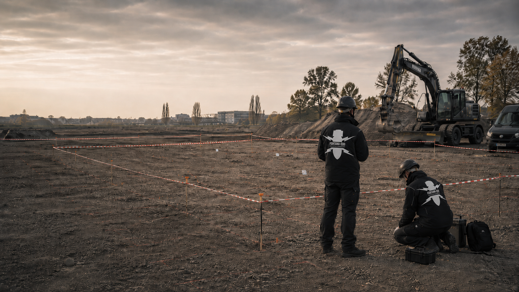
Define clearance objectives, target investigation, exposure, quality control and clearance records for affected areas.
Understand area clearance requirements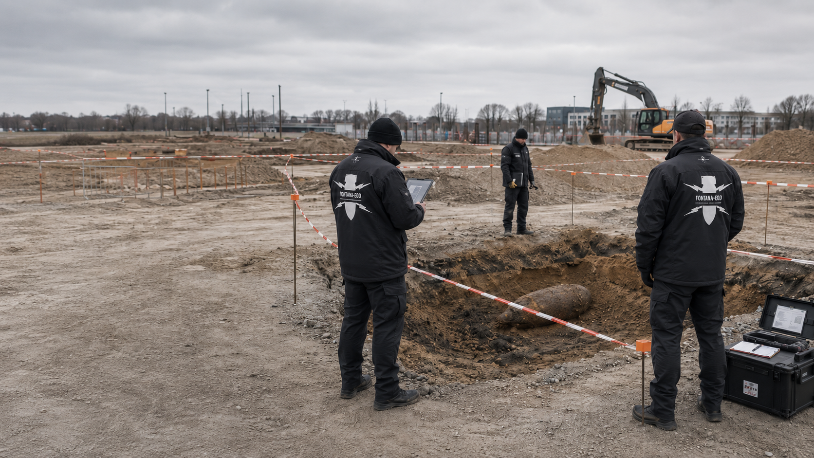
Understand responsibilities, making the area safe, recovery, handover and location-based documentation of confirmed finds.
Understand recoveryBring together historical assessment, surveying, clearance, recovery, supervision of groundworks and documentation.
View all services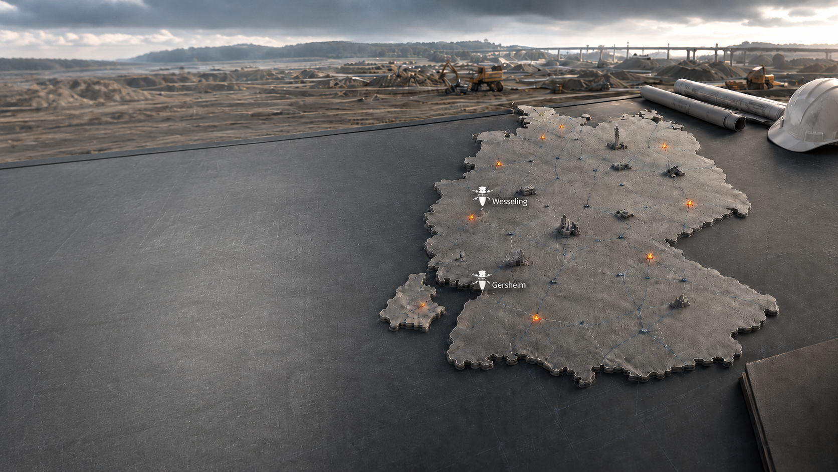
For your enquiry, we need the actual project location and the defined investigation area. Include any existing correspondence and documents with their dates. Regional information helps identify the location; the specific task and conditions on your site determine the survey scope required.
An anomaly initially describes an unusual measurement response. Utilities, scrap metal, reinforcement or other structures can produce similar responses. Location, survey conditions and the basis for suspected ordnance must therefore be assessed together.
Understand interpretation and supporting recordsTechnical specialist services, project responsibilities and the duties of public authorities are different roles. Before work starts, the parties clarify who provides the documents, who commissions the investigation and which competent authority must be involved in the specific case.
Guidance overview and terminologyDo not touch or move a potentially dangerous object. Stop work and leave the danger area. Reporting the find and subsequent actions must follow the instructions of the responsible emergency personnel.
What to do if you suspect an ordnance findThe area, ground disturbance, target object and required findings are recorded for the commission. If different conditions emerge during preparation, their effect on the method and scope of services is clarified.
Changes to survey parameters, obstacles and areas with limited interpretability form part of the documentation. Findings can only be understood when these limits can be read alongside the survey data and the area covered.
Site management must be able to see what the investigation establishes and which areas or anomalies still require work. The report is checked against the plan revision on which the next works are to be based.
Technical information
Ground-penetrating radar, TDEM and magnetometry measure different properties of the subsurface. The brochure explains their applications, preparation of survey areas and the limitations of the findings.

A surface survey uses geophysical methods to investigate a defined area without ground disturbance during the survey itself. It records measurable anomalies spatially, supports their specialist assessment and helps determine further investigation or work required for the proposed construction project.
Magnetometry primarily detects ferromagnetic anomalies in the Earth’s magnetic field. TDEM electromagnetically excites conductive metal objects and measures their time-dependent response. Ground-penetrating radar (GPR) records reflections from layer boundaries, installations and objects. The methods address different physical questions and are selected or combined for the specific project.
Surveying paved areas may be possible if the surface, reinforcement, utilities, layer structure and survey objective allow a suitable method to be used. Ground-penetrating radar or active electromagnetic methods may offer advantages here; however, reinforced concrete and dense metal installations can significantly limit what the findings establish.
No single depth can be stated reliably for every case. Detectability and interpretability depend on object size, material, position, sensor, survey geometry, ground conditions and interference. What matters is whether the working volume relevant to the construction project is covered with sufficient data quality; otherwise, a deep-ground or downhole survey should be considered.
The anomaly is first compared with survey data, sources of interference, subsurface information and the basis for suspected ordnance. Depending on the findings, subsequent work may include relocating the anomaly, supplementary surveying, target investigation, exposure, a deep-ground survey, area clearance or excavation supervision. An anomaly alone does not identify an item of explosive ordnance.
If a suspicious object is found, stop work. Do not touch or move it. Leave the immediate area, warn others without putting yourself at risk and notify the police — in Germany, call 110; outside Germany, use the local emergency reporting arrangements. KBD or the competent local authorities take responsibility for further hazard response according to the actual find.
Depending on the commission, these may include a report, a location and survey-area plan, details of methods and survey conditions, evidence of coverage, an anomaly map, a findings or coordinate list, marked interference zones, limitations and a specialist recommendation for further work.
Key factors include area size and geometry, surface conditions, vegetation, accessibility, interference sources, target objects, required methods, survey density, positioning, traffic or operating restrictions, data volume and documentation objectives. A reliable quotation therefore requires a site plan, a description of the ground disturbance and information about the area.
An initial enquiry does not need to contain a complete survey design. It should, however, show where surveying is required, what ground disturbance is planned, what evidence of suspected ordnance is available and what surface conditions and interference can be expected.
Early coordination reduces the risk of deploying survey equipment on an inadequately prepared site or receiving essential information only after work has begun. Particularly at transport infrastructure, operating sites and projects with several construction sections, time windows, permission to access the area, survey control and those responsible for short-notice decisions should be identified in advance. This can reduce interruptions and allow findings to feed directly into the next project stages.
Useful information includes the project address, federal state or country, site plan, land parcel, construction boundaries, route section, chainage, coordinate system and area size. Exclusions, buildings, slopes, traffic areas and inaccessible zones should be identifiable.
For projects with several construction sections, specify which area is needed first and whether findings should be provided in stages for tendering or site management.
Describe the excavation, utility trench, topsoil stripping, demolition, construction pit, crossing or other ground disturbance. Maximum depth, working width, proposed equipment and construction phase determine the area and depth to be investigated.
Existing information about expected ammunition, unexploded bombs, scrap metal, utilities or other interfering objects helps select magnetometry, TDEM, ground-penetrating radar (GPR) or supplementary methods.
Tell us whether the area is vegetated, gravelled, paved, asphalted, concreted, used by vehicles or operationally active. Include ground investigation records, utility plans, as-built plans, aerial photographic assessments, correspondence with authorities and previous survey reports.
Incomplete or contradictory documents are also relevant. They show which issues still need to be checked before a quotation or survey work can begin.
For an initial assessment, a site plan, area boundaries, a brief description of the ground disturbance, maximum depth, surface condition, known utilities or interference sources and existing documents on suspected ordnance are often sufficient. FONTANA-EOD then identifies which information needs to be added and which method or subsequent service should be considered.
Size, boundaries, subareas, route, access, obstacles and preferred order of work.
Surfacing, vegetation, terrain, utilities, reinforcement, rails, fences, vehicles and technical installations.
Planning, tendering, anomaly assessment, excavation preparation, depth-specific investigation or project records.
Report, site plan, anomaly list, digital geospatial data, raw data, processed data and coordinate format.
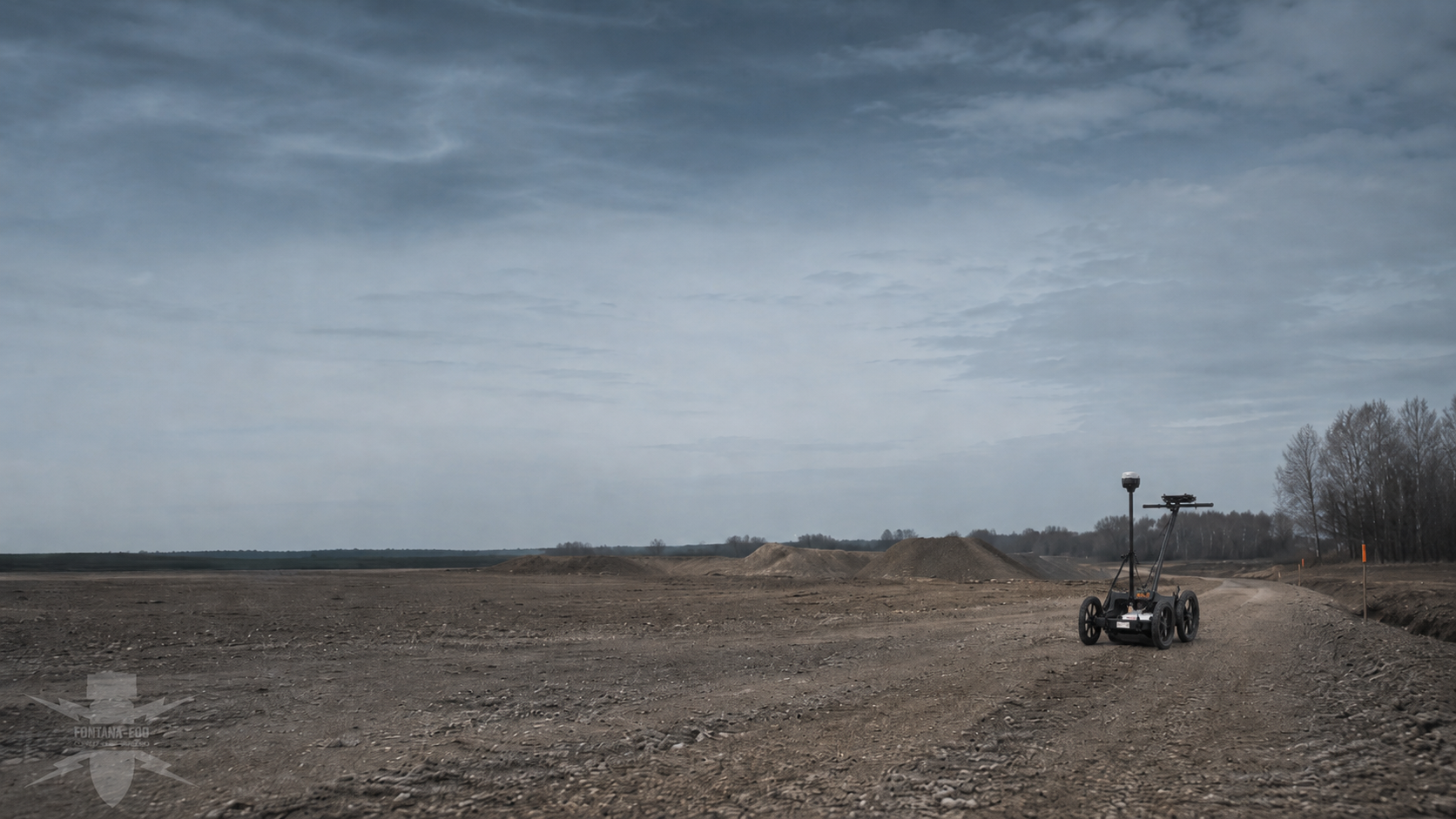
Whether historical aerial photograph analysis, explosive ordnance surveying, surface surveying using GPR, magnetometry or TDEM, deep-ground surveys, downhole surveys, excavation supervision, area clearance or ordnance recovery is needed depends on the location, ground disturbance, depth, ground and existing documents. An early ordnance assessment provides clarity for tendering, programming, occupational safety and construction.
FONTANA-EOD combines its Section 7 SprengG licence, specialists holding Section 20 SprengG certificates of competence, suitable survey and clearance methods, and traceable documentation. Send the site plan, depth of ground disturbance, construction phase and existing documents for an initial technical assessment.


