Project pathway
The quickest route to the right decision.
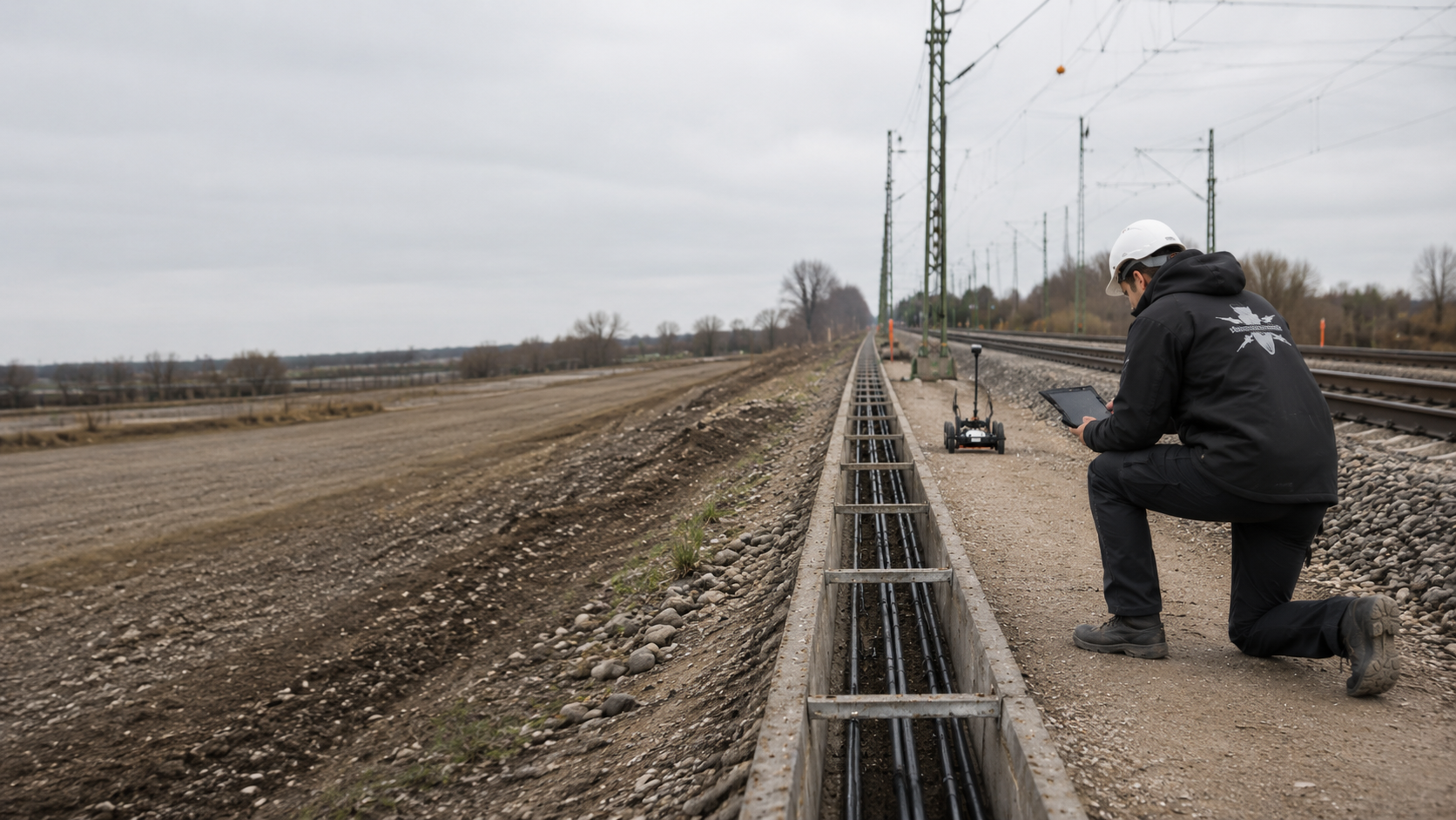
Before track renewal, cable trenching, mast foundations or station alterations, railway designers, construction supervisors and contractors need an explosive ordnance assessment tied to the relevant work section. FONTANA-EOD compares the basis for suspicion with the route, track, chainage and proposed intervention. Send the current section plan, intervention depths, construction stages, possession windows and existing suspected-hazard records.
Identify the track, chainage and construction task.
Define the area, depth and construction stage.
Document handover and unresolved areas clearly.
Explosive ordnance assessment for a railway project depends on the route section, ground intervention and construction stage. Track renewal, cable trenching and mast foundations each need a clearly defined investigation envelope.
Historical suspicion, existing infrastructure and operating constraints determine which investigation is possible and necessary before the next work stage.
Which tracks, working widths and excavation depths are affected, and what becomes accessible only after removal?
Prepare track constructionWhere do the trench, crossings and chambers run, and which existing utilities or buried installations are known?
Prepare cable trenchingWhere are the installation points, how deep are the foundations and which interference sources are nearby?
Assess foundation locationsWhich subareas will be altered, how deep will the works extend and which installations will remain operational?
Assess station areasWhich preliminary investigations are available and what excavation stages are planned next?
Prepare specialist excavation supervisionAt track 20 in Plattling station, GPR surveying, investigations during construction and subsequent volume clearance were combined. The report explains the sequence and spatial limits of the works.
Work stages and survey examples from Plattling · Region: Lower Bavaria
Plattling illustrates the relationship between a GPR investigation and subsequent clearance and verification. Two original visualisations show why an anomalous signal does not yet provide certain object identification.
The Landstuhl survey example shows how magnetic borehole profiles are assessed alongside the documented investigation scope and the limitations of a partial clearance. View the Landstuhl borehole survey example.
Railways, tracks and stations
From surveying to specialist construction supervision: explore our references relating to railway routes, tracks, stations and railway infrastructure. Select a project location to view the relevant services and project information.
Project information is loaded from the reference list.
Select a project location using the search or a red point on the map.
The markers show official settlement centre points. Construction sections and completed services are described in the individual reference. Railway references may also include projects for other rail operators.
Rail network: Deutsche Bahn AG / DB InfraGO AG, data as of May 2026, CC BY 4.0, Data source. Sections operated by DB; lines projected and simplified for display. Base mapping: © BKG (2026), VG250 / GN250, dl-de/by-2-0; Luxembourg: ACT / data.public.lu, CC0.
Tracks, cable routes, foundations, platforms and civil engineering structures differ in working envelope, depth, interference and construction sequence. Services are therefore tailored to the actual task rather than applied uniformly to the entire route.
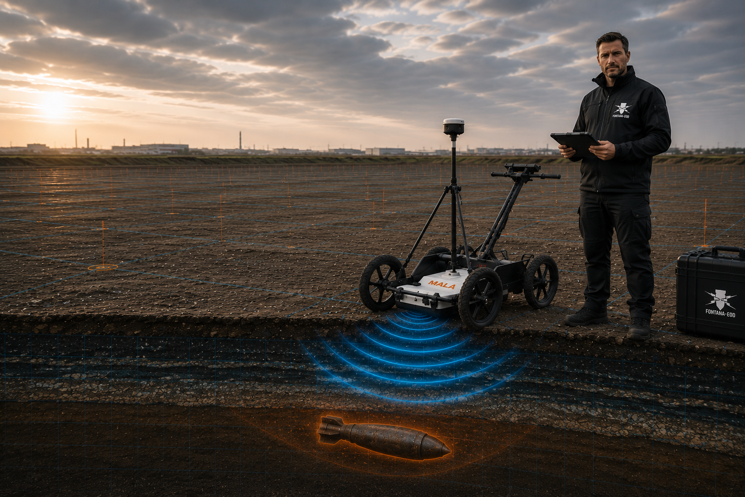
Track, turnout and track-structure renewal involves demolition, formation works, drainage and reconstruction at different depths. Each construction stage must identify which area can be investigated beforehand and which becomes accessible only after track components are removed.
Explosive ordnance assessment is therefore defined by section, with track number, kilometre or chainage, working width, excavation depth and proposed construction method.
Assess surface surveying for track renewal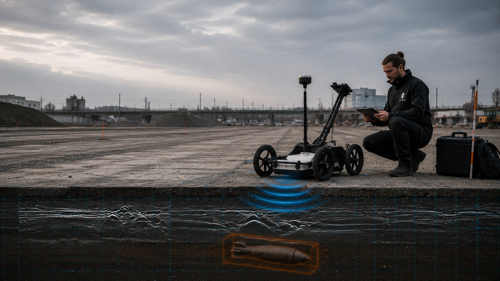
Cable troughs, cable crossings, chambers, signal foundations and new utility routes form narrow, often discontinuous working corridors. Existing cables, traction return circuits, buried infrastructure and documented or unknown utilities affect surveying and execution.
The investigation envelope is referenced to trench alignment, width, depth, start and end points, and subsequent construction stages.
Assess GPR for the cable corridor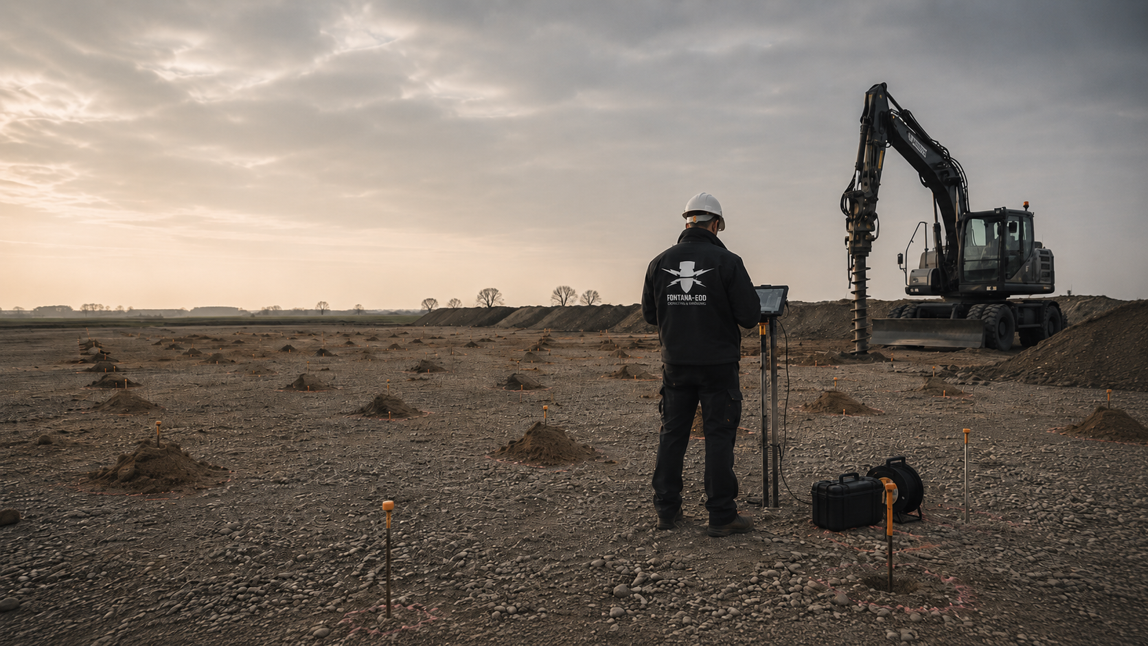
Mast locations, earthing systems, foundations, anchors and cable feeds require point- or line-specific investigations. Above- and below-ground installations can interfere with geophysical measurements, while proposed interventions often extend well below the near-surface working envelope.
Coordinates, foundation geometry, target depth, construction method and operating constraints are considered together when selecting services.
Assess deep-ground surveying for foundation points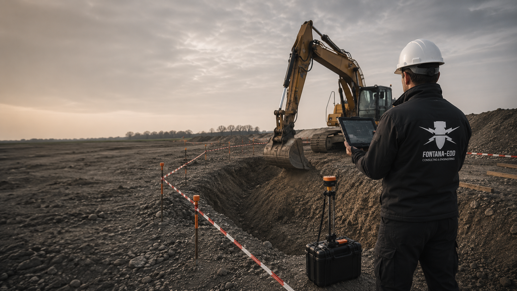
Platform edges, stairs, lifts, roofs, drainage and technical installations involve many individual interventions in a confined area. Existing foundations, utilities and continuing use can further hinder continuous area-wide surveying.
Investigations are divided by subarea, construction stage and intervention depth, keeping uninvestigated zones and subsequent follow-up works clearly identified.
Assess specialist supervision for station alterationsStation areas, loading areas, workshop surroundings and ancillary operational facilities often contain earlier alterations, fill, utility networks and metal installations. Survey conditions can change over short distances.
Reliable investigation distinguishes open areas, zones of technical interference, deep interventions and ongoing earthworks rather than treating the entire site with a single method.
Assess surface surveying for operational areasLevel crossings combine track, road construction, drainage, cables and signalling. Pipe jacking, thrust boring and open crossings also involve different depths and responsibilities.
The investigation envelope and records are therefore referenced to alignment and depth. Interfaces between road and railway areas remain clearly separated in plans and documentation.
Assess GPR at crossingsAbutments, piers, shoring alignments, temporary bridges, culverts and excavations create deep point and linear interventions. Existing structures, reinforcement and historical foundations often restrict area-wide surveyability.
Explosive ordnance assessment is tied to the actual foundation and working envelope and coordinated with borehole layouts, shoring, excavation sequence and possible alternative measures.
Assess deep-ground surveying at foundations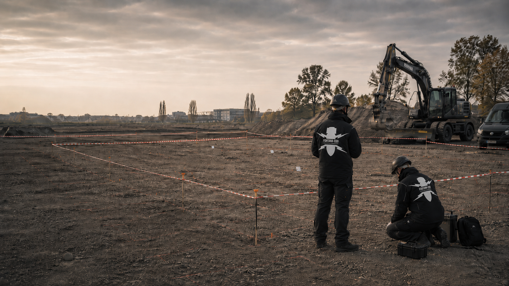
Extensive track layouts, turnout areas, cable systems, drainage and former operational uses create heterogeneous ground and interference conditions. Large sites must also be divided into manageable construction and handover sections.
Investigation links historically suspect areas with current tracks, operational areas, proposed interventions and clearly numbered subareas.
Assess area clearance around tracksWhere track structures, utilities, existing infrastructure or dense interference prevent complete prior investigation, specialist supervision of actual excavation may be required. Its scope is limited to defined excavation layers, working widths and construction sections.
Before work begins, the excavation sequence, hold points, reporting arrangements, safety organisation and documentation are agreed with site management and the contractor.
Assess excavation supervision for route construction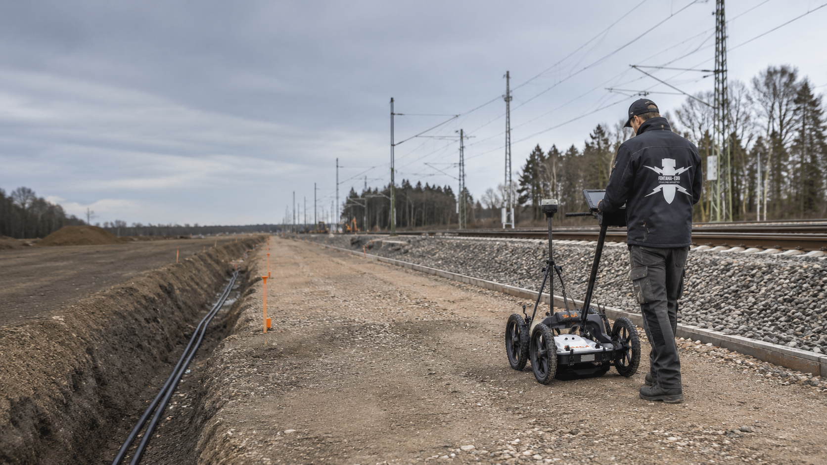
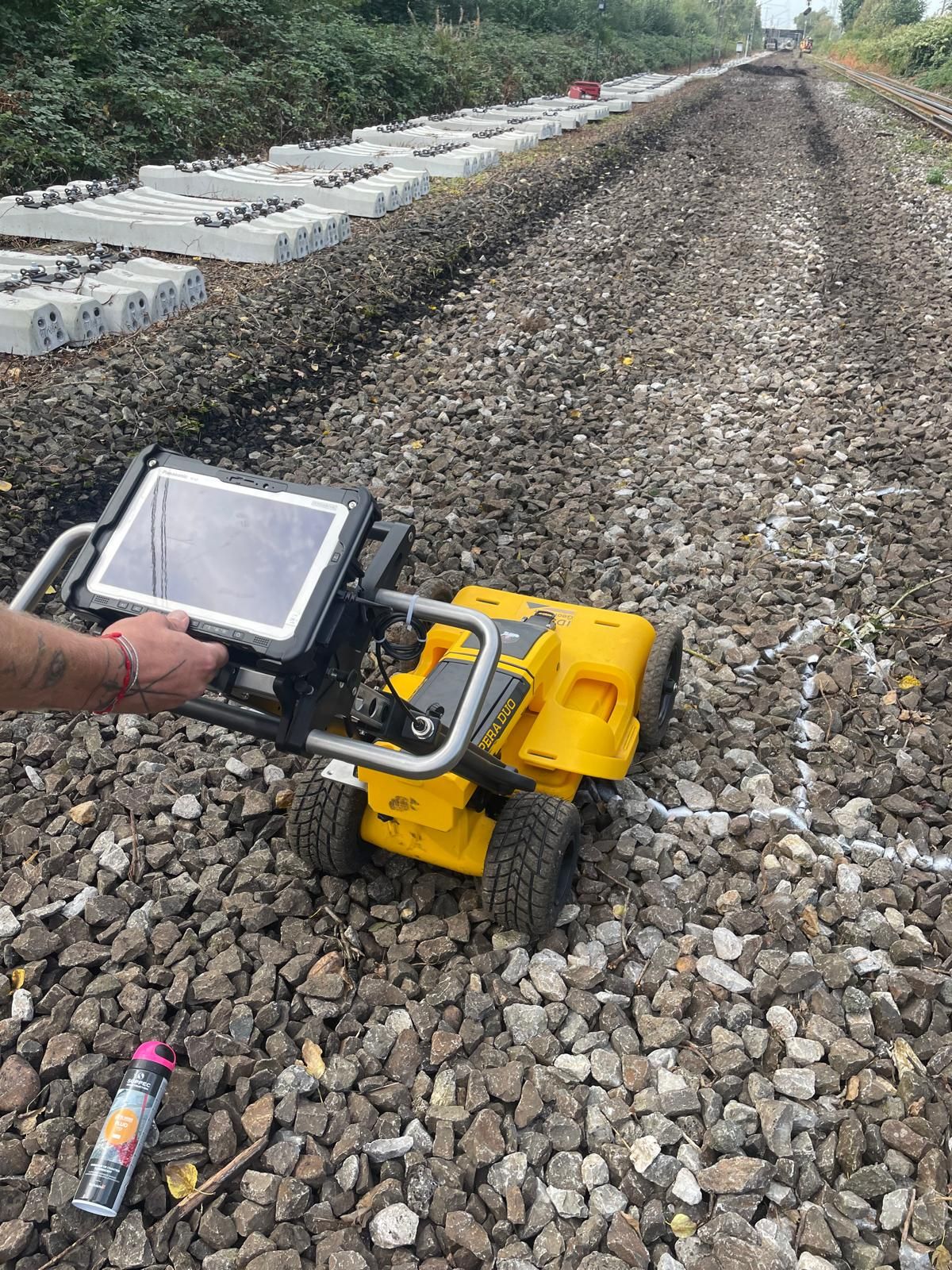
GPR can provide structural information where rails, utilities, foundations or paved surfaces limit other methods or additional ground information is needed. Its suitability depends on the survey objective, material construction, moisture, profile routes and interference.
Application is planned for the particular survey section and assessed against known installations and possible follow-up methods.
Assess GPR suitability around tracksTechnical information
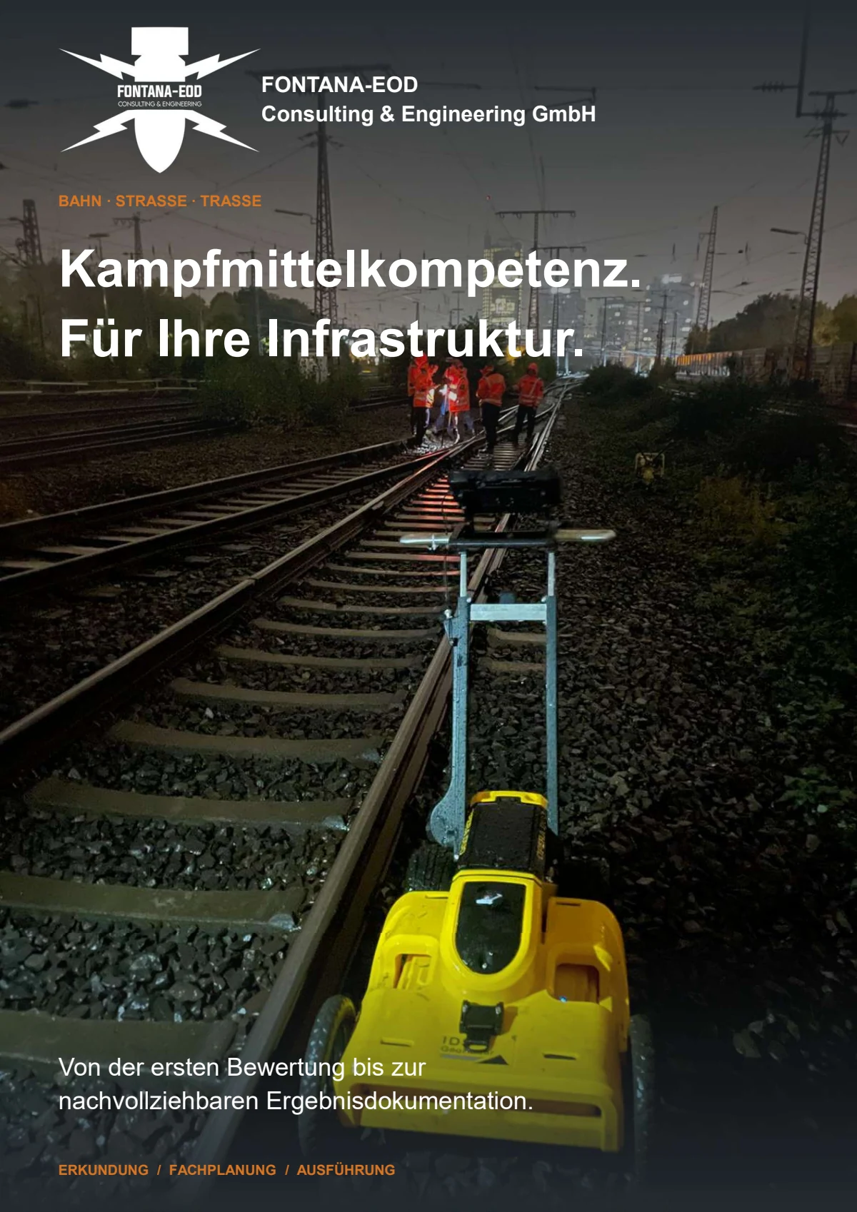
The brochure shows how FONTANA-EOD combines historical investigation, specialist planning, surveying and construction supervision in infrastructure projects. It explains trackside constraints, method selection and limitations, and result documentation.
The design stage and construction conditions determine the conclusions required. Services should not be retrofitted to a construction method that has already been fixed.
In early project phases, route corridors, structures and main intervention areas are often not final. Historical records and existing statements are therefore first related to the options and anticipated working envelope.
The result should identify sections requiring more detailed investigation and data still missing before a technical service is tendered.
Define historically suspect areasOnce track alignments, cable routes, mast locations, excavations or shoring alignments are established, investigation needs can be described geometrically. Area, depth, construction stage and required conclusions are aligned to the same plan revision.
This allows area-wide, point-specific and construction-stage services to be separated and scheduled.
Define service scope by construction taskA general item called “explosive ordnance surveying” leaves the required area, depth and result undefined. Comparable quotations require clear investigation objectives, access, operator requirements, qualifications, data formats and documentation.
For phased works, handovers, acceptance criteria and services for unsurveyable areas must be defined beforehand.
Define specifications and documentationBefore fieldwork, the working area, protection arrangements, access, isolations, machinery, material storage and sequence must be coordinated. Missing authorisations or plans can make a short working window unusable.
Deployment planning therefore identifies prerequisites, contacts and decisions required before work begins.
Coordinate working windows and accessPiled foundations, mast bases, signals, shoring piles and anchors require point- and depth-specific investigation. An area-wide surface survey does not automatically cover this intervention geometry.
Borehole locations, target depths, diameters, construction methods, existing utilities and potential interference form the basis for survey planning.
Define borehole locations and the depth envelopeIf the construction sequence changes or an area cannot be surveyed beforehand, the follow-up decision must address the actual intervention. Excavation supervision may cover defined work stages; further measures for anomalies or finds must be specified separately.
Changes are documented by location, depth and affected construction phase so that the limits of existing records are not exceeded unnoticed.
Provide specialist support for excavation and changesHistorical assessment, technical investigation and specialist construction supervision serve different purposes. Their results must refer to the same section and the ground interventions proposed there.
Historical records establish the need for investigation; the target, ground and intervention geometry determine the technical investigation. If complete preliminary investigation is impossible, an appropriate way forward is defined before ground disturbance. During construction-stage explosive ordnance surveying, the accessible layer is first surveyed and assessed technically. Authorised removal then proceeds in layers under additional visual supervision. These steps repeat to the agreed formation level.
Initial situation: Reliable suspected-hazard information is unavailable or contradictory for the proposed working envelope.
Technical step: Historical aerial photographs, maps, previous uses and existing records are referenced to the current route geometry.
Result: Defined suspect areas, data gaps and a reasoned recommendation for further technical investigations.
Initial situation: Near-surface work is planned on the formation, access path, operational area or route section.
Technical step: Magnetometry, TDEM, GPR or a combination is selected according to the target, ground, surface and interference.
Result: Georeferenced survey data identifying anomalies and limitations, with a clear recommendation for further investigation.
Initial situation: Piles, masts, signals, shoring alignments or boreholes penetrate a deeper, narrowly defined envelope.
Technical step: Investigation geometry and borehole surveying are tailored to point location, target depth, construction method and expected interference.
Result: Point- or alignment-specific survey and assessment records for the defined depth envelope.
Initial situation: Track structures, existing infrastructure, utilities, reinforcement or lack of access prevent complete surveying beforehand.
Technical step: Unsurveyable zones are marked spatially and linked to exposure, supplementary depth investigations or excavation supervision.
Result: An agreed approach for actual construction conditions rather than an inaccurate blanket conclusion.
Initial situation: Survey data or earthworks reveal a relevant anomaly or suspicious object.
Technical step: Location, depth, working environment and responsibility are assessed; exposure, clearance or recovery follows within the defined framework.
Result: Finding-specific records, documented handovers and clear boundaries for unresolved areas.
Initial situation: Clients, construction supervisors or contractors need reliable conclusions about the completed construction section.
Technical step: The basis for suspicion, services, survey or working area, limitations and follow-up decisions are assembled together.
Result: Traceable documentation with a clearly defined spatial, depth-related and temporal scope.
At Kaldenkirchen terminal, FONTANA-EOD supervised excavation across several work sections and supplemented this with GPR investigations. The project report describes instrument-based checks during excavation and section-by-section investigation of the reached formation level. The documented investigation period runs from 27 July to 14 September 2026.
According to the report, the described works produced no indications of explosive ordnance. However, individual margins beside existing foundations could not be surveyed to establish clearance. The conclusions apply to the documented work sections and do not cover those unverified margins. They cannot support an unrestricted conclusion for the entire terminal.
Scope: the sections and boundaries documented in the report and its appendices.
Ground-penetrating radar · Ordnance specialist supervision of groundworks · Explosive ordnance assessment in North Rhine-Westphalia · Further reference information
The period from 27 July to 14 September 2026 describes the documented works. It establishes neither continuous investigation of every terminal area nor clearance of uninvestigated margins.

Reference historical records and previous results to the current route section, track and plan revision. Records for a neighbouring section do not automatically apply to the proposed intervention. State the unresolved question in your enquiry and identify missing records or records that cannot be assigned unambiguously.
Assess the basis for suspicionFor each section, describe the location, depth and construction method of the proposed intervention. A cable trench, mast foundation and larger construction site may require different investigations. Rails, installations and restricted access inform selection. The specification then identifies each section’s task and the coordination needed for its working window.
Clarify area and depth referencesReliable service selection requires spatial, construction and operating information to be considered together. Missing constraints can otherwise lead to incomparable quotations or changes within short working windows.
Route, track, kilometre or chainage, structural reference and working width must agree between plan and site. Where construction stages change, subareas receive their own identifiers. This spatial organisation prevents survey data, borehole locations or excavation records being assigned to the wrong plan revision.
Possession windows, closed or adjacent operational tracks, isolations, protection measures, access and permitted equipment movements determine practical execution. Available time is planned by achievable survey or work output in each section, not route length alone.
Rails, sleepers, ballast, paved paths, platform surfacing, fill and moisture affect geophysical methods differently. Method selection considers expected materials and layer changes and whether the relevant intervention envelope can be adequately investigated from the existing surface.
Cables, cable troughs, traction return circuits, signalling, foundations, reinforcement and metal components may mask survey data or restrict working envelopes. Existing records therefore provide not only location information but also a basis for assessing known signatures and potential interference zones.
Cable trenches, excavations, drilling, piles, mast foundations, shoring and thrust boring each impose different requirements on investigation geometry and safety distances. Maximum depth alone is insufficient; diameter, alignment, working envelope and equipment must also match the investigation.
Clients, designers and construction supervisors need different levels of detail, but the same revision status. Reports, plans, data schedules and unresolved issues are organised so that the next construction phase, procurement step or supplementary investigation can be clearly identified.
The methods answer different questions. Reliable planning combines them only where the actual working envelope and required conclusions justify it.
Technical contribution: Establishes whether and where historical explosive ordnance suspicion exists and which subareas need further technical investigation.
Key limitation: Does not reveal objects currently underground and does not replace technical investigation of the proposed intervention.
Investigate historical suspicionTechnical contribution: Records reflections at material and structural boundaries and, in suitable sections, can add information about installations, layer changes and anomalous signatures.
Key limitation: Does not identify explosive ordnance directly; track structures, moisture, utilities and known structural components may limit interpretation.
Assess GPR for the survey sectionTechnical contribution: Support area-wide detection of magnetic or electrically conductive anomalies where the surface, interference and target allow interpretable surveying.
Key limitation: Rails, reinforcement, cables and technical installations can mask signals; deeper ground interventions may require separate investigation.
Compare area-wide survey methodsTechnical contribution: Investigates the defined point or linear envelope of deep foundations, masts, piles, shoring alignments and boreholes.
Key limitation: Conclusions apply to the defined investigation geometry, not automatically to neighbouring areas or other construction stages.
Define the depth envelope for foundationsTechnical contribution: Combines technical investigation and assessment of each excavation layer with subsequent controlled removal. Visual supervision supplements the technical investigation; anomalies trigger agreed hold points and reporting arrangements.
Key limitation: Covers only the supervised excavation layers and does not replace investigation outside the area actually worked.
Plan excavation supervisionTechnical contribution: Address defined suspect points or affected areas against an established objective and document exposure, findings and handover.
Key limitation: Scope and responsibility depend on the commission, actual findings and local procedure; uninvestigated areas remain outside the conclusions.
Clarify findings investigation and handoverA technical service becomes useful to a railway project only when the starting position, investigated area, data, limitations and conclusions remain understandable to project partners who were not involved.
Using this information, FONTANA-EOD agrees with you which areas and depths need investigation. Subsequent records describe the route, track or structural section investigated, the method used, limitations encountered and follow-up measures still required for the next construction phase.
After exposure or clearance, completed steps and findings are recorded in the clearance record using the same section reference. The survey report and subsequent clearance record remain clearly linked in the project file.
Track number, kilometre or chainage, structure, working width and construction section provide the spatial reference. Different plan revisions are identified so survey data and construction remain tied to the same geometry.
For long routes, subareas receive unique names used consistently in plans, field records, data storage and reports.
Historical assessments, authority correspondence, previous reports, known finds and earlier construction are documented with sources and spatial references. The report identifies contradictory information and missing records so these can be resolved before further work.
This makes the reason for investigating a section and the assumptions behind method selection traceable.
Areas, profile alignments, cable trenches, borehole locations, foundations, shoring alignments and excavation layers are described with target depths and construction methods. Records must show whether the investigation actually covers the later working envelope.
Relocations or plan changes are updated spatially before conclusions are applied to the changed intervention.
Methods, equipment configuration, grid or profile routes, positioning, surface conditions, access and interference are recorded so that the data can be assessed technically. Excavation supervision additionally records excavation layers, equipment use and hold points.
The records link actual fieldwork with the agreed service scope.
Inaccessible zones, shielding, technical interference, changed construction conditions and depths not reached are identified spatially. For each area, the need for another method, later exposure or investigation during construction is stated.
This keeps documentation usable even where different sections required different methods.
Reports, plans, anomaly or findings schedules and quality checks are brought together into a clear conclusion. It applies to the documented area and depth envelope and the construction conditions known at the time of the work.
Unresolved issues, follow-up measures and responsibilities for the next construction phase are identified explicitly.
The sequence is tailored to the project phase, possession window and construction method. Results are handed over to those preparing the next design or construction section.
Route, track, kilometre or chainage, structure, working width, intervention type and target depth are clearly marked on a current plan.
Historical assessments, authority information, earlier reports, utility and as-built plans and known finds are referenced to the same section.
Track structures, operational use, possession windows, isolations, protection, access and available working areas determine when and how fieldwork is possible.
Area-wide, point-specific, depth-related or construction-stage services are selected according to the survey objective, ground, interference and subsequent ground intervention.
Surveys, borehole investigations or excavation supervision use clear location identifiers and documented working limits.
Survey data, anomalies, interference, uninvestigable zones and field observations are assessed against the project question and proposed intervention.
Supplementary surveys, exposure, depth investigations, excavation supervision or investigation of findings are defined separately for the affected sections.
Reports, plans, records, limitations and unresolved issues are prepared so that designers, construction supervisors and contractors use the same documented revision.
Choose the situation matching your project’s current stage. Detailed assessment is then referenced to the route, section and intervention.
For early design, options or new construction sections, historical sources and existing statements are referenced to the actual route envelope.
For area-wide investigations, the target, surface, ground, existing utilities and interference are compared before a method is chosen.
Mast, pile, signal and shoring points need their own location and depth references with agreed investigation geometry.
For incompletely investigated areas, the technical suitability of investigation during construction is assessed. The construction sequence, excavation layers, hold points and reporting arrangements are agreed accordingly.
The investigation objective, working limits, quality, data format and required documentation are defined clearly for procurement and acceptance.
A site plan, project description, existing official conditions and unresolved questions are enough for an initial technical assessment of the next work stage.
Within short working windows, surveying, positioning and verification must match the authorised section. FONTANA-EOD considers construction conditions, available access, protection of the working area and the required documentation. Inaccessible areas or differing conditions are recorded on site and assessed for the next construction phase.
At the outset, the construction decision to be supported is defined. This determines the working envelope, depth, target and technical conclusions actually required. Sections with different track structures, ground or interference conditions are treated separately.
Site deviations are marked on the plan and compared with the agreed investigation scope. This keeps the need for supplementary investigation, later exposure or excavation supervision visible.
The report records which areas were investigated, which conclusions the data supports for the next construction section and what remains unresolved.
Chainage, track, structure, working width and depth are recorded consistently in design, fieldwork and reports.
The method follows the proposed intervention and survey conditions, rather than a general equipment preference.
Access, possession windows, protection, isolations and simultaneous trades are included in deployment planning before work begins.
Survey and positioning data, field records, deviations and interpretation are checked for completeness and plausibility.
Unreached areas, technical interference and changes in construction conditions remain spatially visible.
The conclusion identifies which section is prepared for the next work stage and where further measures are required.
Clients, designers, construction supervisors, contractors, specialist contractors and competent authorities need the same plan revision and clear decision-making arrangements. Roles are agreed before work begins so deviations and finds reach the right party promptly.
Defines the construction task, project boundaries, programme and required conclusions. Provides existing design, as-built and suspected-hazard records and decides on commissioning and subsequent project measures.
Translates the project into specific tracks, alignments, structures, cable routes, borehole locations, depths and construction stages. This information underpins specifications and method selection.
Coordinates plan revisions, access, work authorisations, handovers and deviations. Ensures that the documented position matches the construction section actually executed.
Observe agreed working limits, excavation layers, hold points and reporting arrangements. Changes to construction method, depth or sequence are reported before implementation.
Assesses records, develops the commissioned approach, carries out specialist services within the agreed area and documents data, findings, limitations and follow-up measures.
In Germany, explosive ordnance disposal services and local authorities handle hazard response or finds according to the federal state, project location and actual findings. Reporting and coordination arrangements are clarified for the site concerned.
Public-order authorities and building control may be involved depending on local procedures and the construction task. Existing requirements are assigned to the actual site and working area. Commercial specialist services, operational work authorisation and authority decisions on finds each have their own contact and reporting arrangements.
Requirements depend on the activity, project location, construction conditions and actual findings. Specifications, responsible personnel, protection and documentation are therefore defined for each individual work section.
In Germany, section 7 SprengG concerns the commercial licence for activities requiring authorisation; section 20 concerns the certificate of competence for responsible persons. Under section 1b SprengG, activities involving found ammunition also include searching for it. The requirements applicable to a project depend on the work actually commissioned and its organisation.
DGUV Information 201-027 supports risk assessment and protective measures for explosive ordnance clearance. The BFR KMR construction guidelines describe investigation, planning, quality and documentation within their defined federal scope; their application to a particular project is clarified separately. Work on or near tracks additionally requires project- and operator-specific arrangements for access, protection, isolations and working limits.
Preliminary investigation, technical investigation and an unexpected find each require separate decisions. If a suspicious object is found, stop work. Do not touch or move it; leave the immediate area and warn others without putting yourself at risk. In Germany, notify the police immediately on 110; outside Germany, use the local emergency reporting arrangements.
The First Ordinance to the German Explosives Act (1. SprengV) includes requirements for specialist competence and state-recognised courses. In railway and route construction, the necessary qualifications are assigned to the specific technical task; access and railway operational protection are arranged additionally.
DGUV Rule 113-003 concerns dismantling or destroying explosives or corresponding articles and also includes disposal of found ammunition. Its application follows that activity scope and is coordinated with responsibilities for the railway section concerned.
The company, responsible personnel and scope of responsibility must suit the actual service.
Access, possession windows, isolations, protection measures and working limits are established before fieldwork.
The specification clearly identifies the area, depth, target, method and expected documentation.
Work status, limitations, findings and follow-up measures are assembled with spatial references.
Plan revisions, service objectives, qualification requirements, operator information and supporting records are compared.
All parties must know the working limits, communication arrangements, hold points and plan changes.
Stop work, leave the object undisturbed and leave the immediate area. Warn others without putting yourself at risk. In Germany, notify the police immediately on 110; outside Germany, use the local emergency reporting arrangements.
Together, the documents provide a traceable record of a railway section’s work status. They use the same plan revision and spatial reference.
Links historical evidence with today’s route, tracks, structures and proposed interventions. Subareas and data gaps receive unique identifiers.
The plan provides a basis for survey areas, borehole locations and subsequent handovers.
Understand the historical basis for suspicionShows the grid, profile alignments, vehicle or walking routes, reference points, obstacles and inaccessible zones. For linear projects, each survey remains linked to chainage or a section number.
Interpretation and construction can then use the same spatial reference.
Assess survey profiles and structuresIncludes coordinates, target depth, investigation geometry, drilling method, survey conditions and point-specific assessment for masts, piles, signals or shoring alignments.
Relocated or omitted points are documented with reasons and the new location.
Investigate borehole locations and foundation envelopesRecords the construction section, excavation layer, equipment, observations, interruptions and defined hold points. Anomalies are described by location and working conditions.
The record clearly links the supervised earthwork stage with subsequent conclusions.
Provide section-specific excavation supervision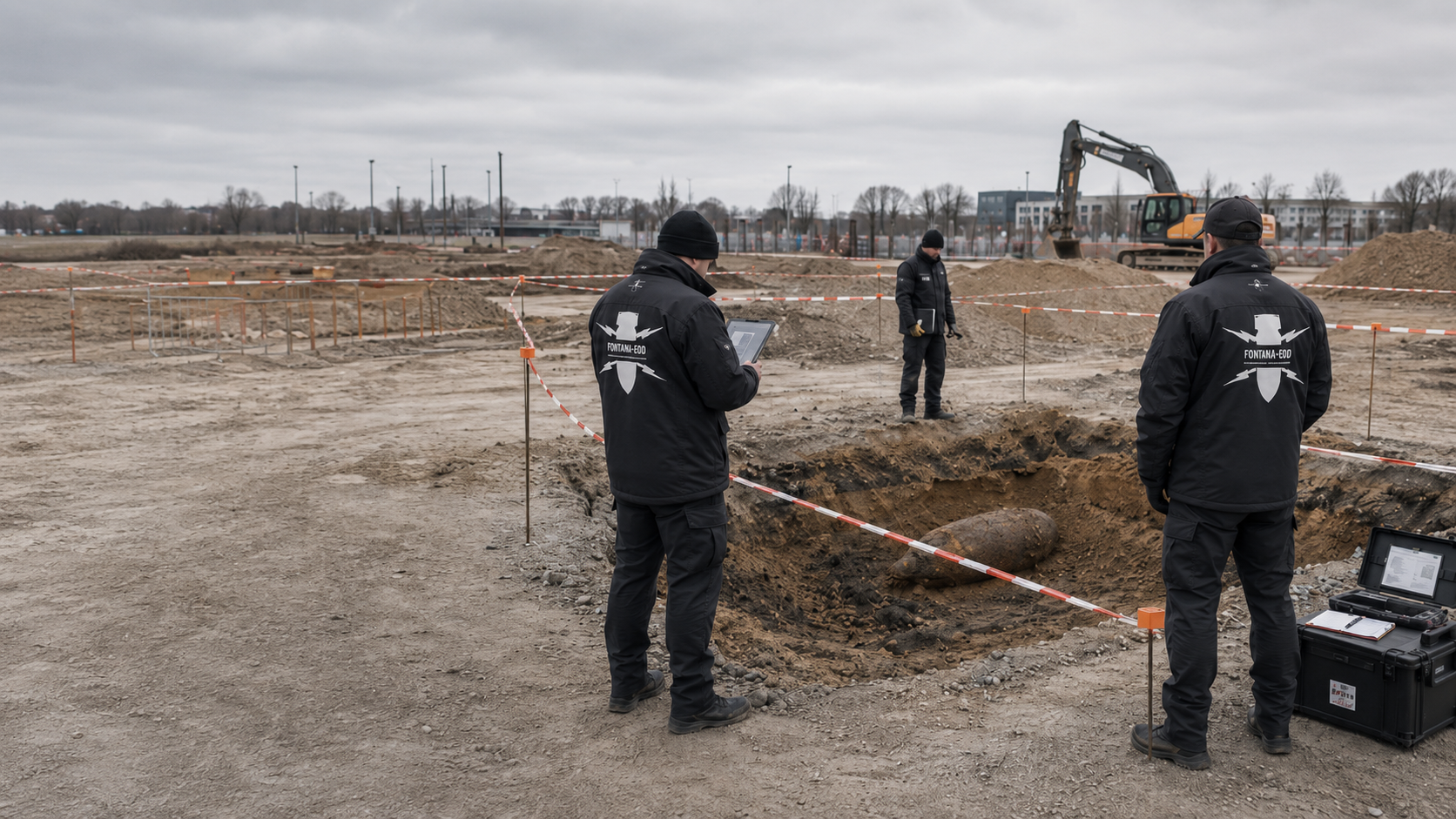
Brings survey anomalies, supplementary investigations, exposures and findings together under consistent identifiers. Status and recommended follow-up measures remain traceable for construction supervisors and clients.
Unresolved points are kept distinct from completed areas.
Link anomalies with findings investigation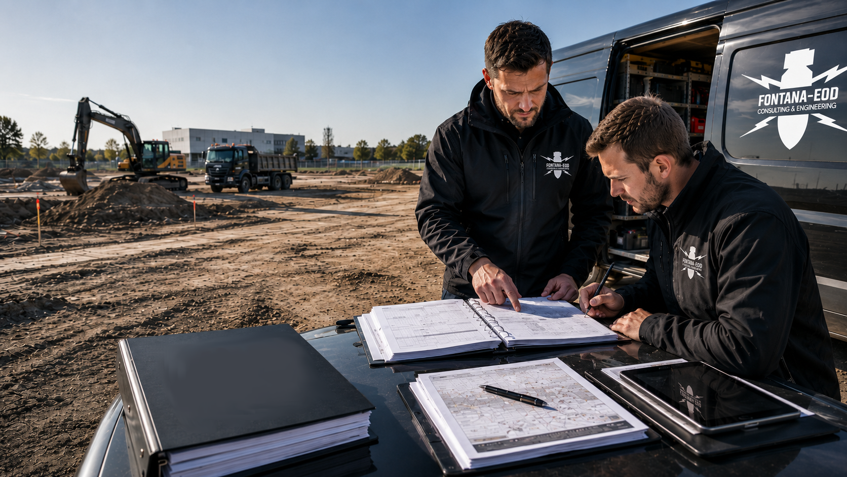
Combines the starting position, service scope, investigated area and depth, data quality, limitations and result. Maps and schedules use the same plan revision.
The report explicitly identifies which construction phase or decision this evidence can support.
Prepare the completion report and handover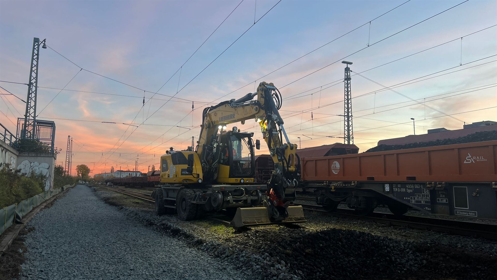
Depending on the project stage, the priority may be method selection, depth investigation, excavation supervision, documentation or an adjoining civil engineering area.
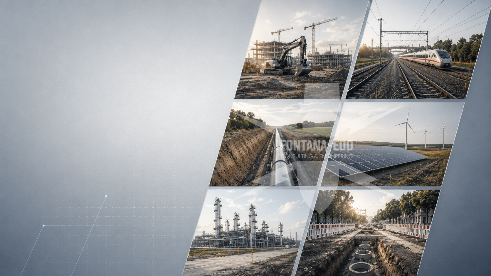
Select other project types, such as road construction, energy, municipal infrastructure or industrial sites, according to their specific constraints.
Select the project type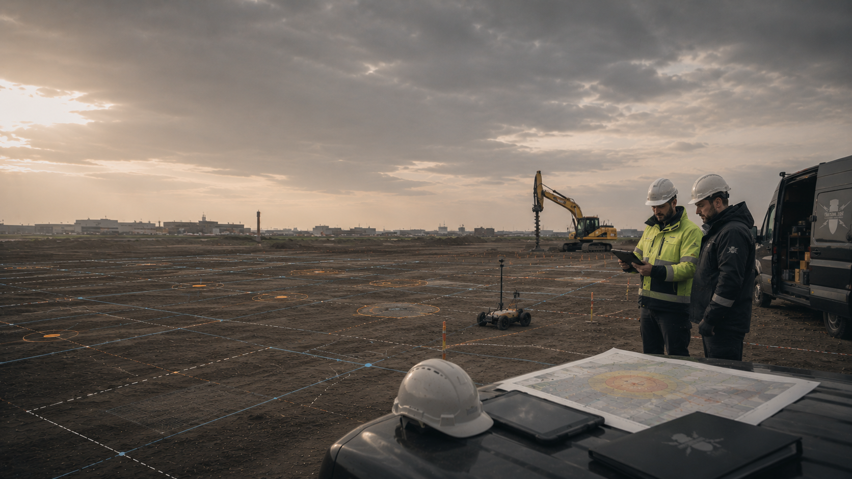
Compare historical assessment, surface surveys, deep-ground surveys, excavation supervision, clearance and documentation against the project’s current stage.
Define service needs with specialist inputDistinguish magnetometry, TDEM and GPR by target, surface, ground and interference.
Choose a suitable surface survey methodPrepare borehole locations, piles, masts and shoring alignments with their own investigation geometry and documented depth.
Plan point- and depth-specific investigationsSupervise earthworks in incompletely investigated areas with defined excavation layers, hold points and reporting arrangements.
Tailor specialist supervision to the excavationOrganise specifications, clearance or investigation designs, quality checks and section handover for procurement and the project file.
Agree a binding documentation scope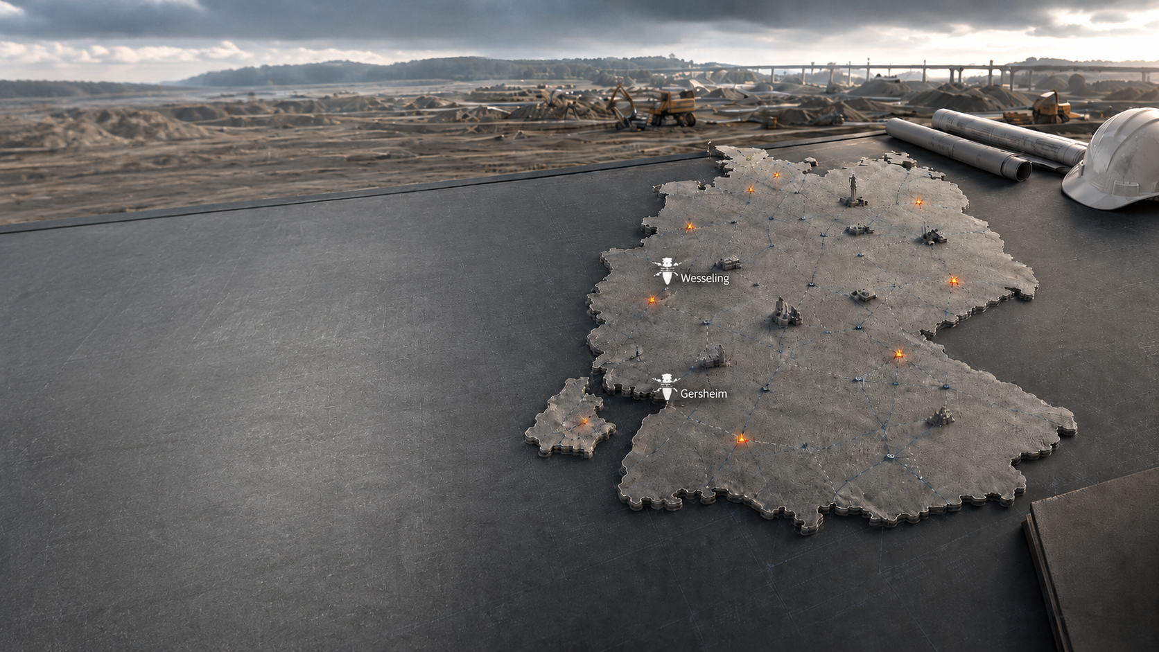
Consider the project location, federal state and local interfaces when coordinating further work.
Clarify regional responsibilities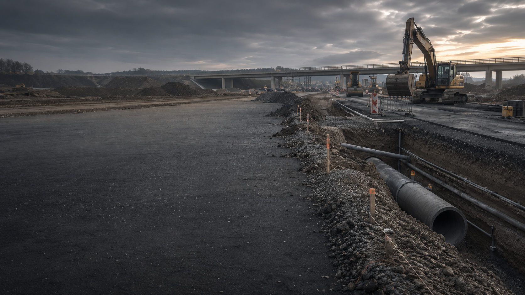
Assess adjoining areas outside the railway corridor separately by road construction, sewer works, excavations and municipal civil engineering.
Prepare a road or civil engineering projectFor long railway routes, identify individual locations and sections. Assign information, plans and contacts to the relevant works. Local requirements, ownership boundaries and operating areas are considered during coordination. FONTANA-EOD needs the current route plan, intervention areas and existing requirements for the investigation; the regional overview provides initial orientation.
An available working window does not establish that every desired investigation scope is technically achievable within it. Access, section length, surface conditions and required coordination must be considered together. Both timing and actual intervention geometry therefore matter in an enquiry. Planning can identify preparatory work needed earlier and questions still to resolve for the working window. The find report from Plattling station documents a trackside case in which FONTANA-EOD found the bomb.
Explore results and terminologyBefore the next ground intervention, the report’s areas and depths are compared with the current construction plan. A shifted alignment, additional chamber or deeper foundation may lie outside the previous scope. Such changes are submitted explicitly for specialist assessment. The existing report is retained; any supplement should identify its new question and the plan revision to which it relates.
Understand the service scopeRoute, track, chainage and intervention depth define the investigation envelope. Access, possession windows and infrastructure conditions determine which services can be delivered within the proposed working window.
Assessment should begin once the route section, construction task and anticipated intervention depths are identifiable. Early work first relates historical suspicion to the project corridor. Before tendering and construction, this is developed into specific areas, borehole locations, excavation envelopes, access, working windows and documentation.
Required information includes a clear route and section description, track numbers, kilometre or chainage, working widths, crossings, structures, proposed depths and construction phases. Historical assessments, survey areas, borehole locations, inaccessible zones and findings use the same spatial reference. Existing authority correspondence is supplied in full with appendices, conditions and associated plans. The competent authorities determine any additional documentation required for the specific project.
This depends on the intervention and survey conditions. Rails, fixings, cables, foundations, reinforcement and metal-rich fill can limit methods. Deep foundations or shoring alignments additionally need point- and depth-specific investigation. Unsurveyable areas may require another method or excavation supervision.
GPR can be useful where structural ground information is needed and the surface and material construction allow interpretable surveying. Around tracks and routes, suitability is assessed section by section against the target, moisture, track structure, utilities, foundations and profile routes.
Access, protection, isolations, possession windows, machinery movements and simultaneous trades are included in deployment planning before fieldwork. Services are divided so that surveying, drilling or excavation supervision can complete a clearly defined section within the available working window.
Required details include the investigation or clearance objective, area and depth references, construction conditions, access, operator requirements, qualifications, methods or selection criteria, quality checks, data formats, treatment of limitations and required documentation. General service items often produce quotations that cannot be compared meaningfully.
Effort, duration and cost also depend on section length, intervention depth, the number of survey or borehole points, interference, access, possession windows and documentation scope. These conditions are stated for each section so quotations can be compared on the same basis.
It describes which route, track or structural section was investigated, the method used and the depth reached. Survey conditions, findings, uninvestigated areas and further measures are identified spatially. Conclusions apply to the documented work scope and underlying construction conditions.
If an unexpected suspicious object is found, stop work. Do not touch, move or excavate it further. Leave the immediate area and warn others without putting yourself at risk. In Germany, notify the police immediately on 110 and inform site management. Outside Germany, use the local emergency reporting arrangements. The competent authorities determine further action according to the actual find.
A useful enquiry does not require a finished specification. It should, however, identify the route or infrastructure area concerned and the ground intervention being prepared.
For multi-phase programmes, priorities, possession windows and proposed handover dates help divide the work into technically meaningful sections.
Provide the route, track number, kilometre or chainage, station or infrastructure area, working width and construction section. Site plans should show the current revision, proposed partial handovers and adjoining installations.
For crossings and civil engineering structures, alignments, start and end areas and connections to roads, utilities or watercourses are useful.
Describe cable trenches, track renewal, excavation, mast, pile or signal foundations, shoring, thrust boring, platform works or bridge construction with maximum depth and dimensions.
Possession windows, access, overhead-line status, equipment, simultaneous trades and proposed sequence affect the methodology and the section that can realistically be completed.
Include existing aerial photograph assessments, authority correspondence, previous survey reports, utility and as-built plans, geotechnical records, borehole schedules and details of known anomalies.
Also state the conclusions needed for design, procurement, construction supervision or section handover.
A small set of records is often enough for initial assessment. Send a current site plan and route and section description. Describe the proposed intervention, maximum depth and working window. Include existing information about suspected hazards.
FONTANA-EOD then identifies the appropriate service area, missing background information and details still needed for a reliable quotation.
Route, track, kilometre or chainage, structure and working width.
Type, geometry, maximum depth and proposed construction method.
Track structure, existing infrastructure, access, possession windows and simultaneous works.
Suspected-hazard assessment, utility plans, geotechnical data, earlier reports and authority conditions.
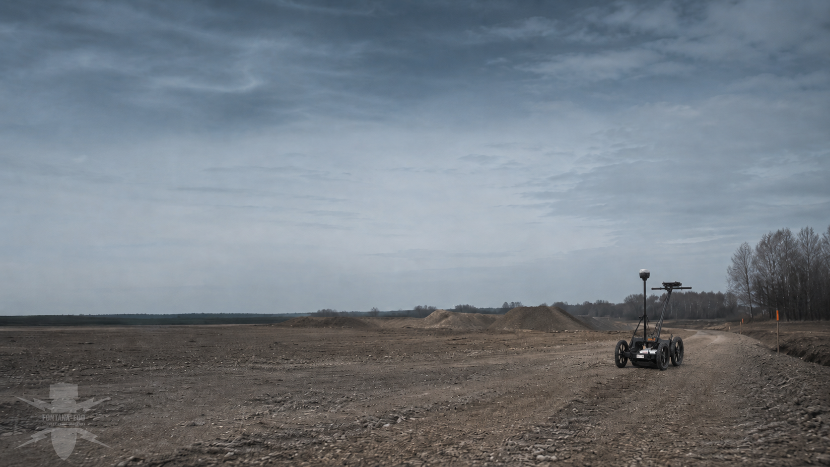
Whether historical aerial photograph analysis, explosive ordnance surveying, surface surveying using GPR, magnetometry or TDEM, deep-ground surveys, downhole surveys, excavation supervision, area clearance or ordnance recovery is needed depends on the location, ground disturbance, depth, ground and existing documents. An early ordnance assessment provides clarity for tendering, programming, occupational safety and construction.
FONTANA-EOD combines its Section 7 SprengG licence, specialists holding Section 20 SprengG certificates of competence, suitable survey and clearance methods, and traceable documentation. Send the site plan, depth of ground disturbance, construction phase and existing documents for an initial technical assessment.


