Project pathway
The quickest route to the right decision.
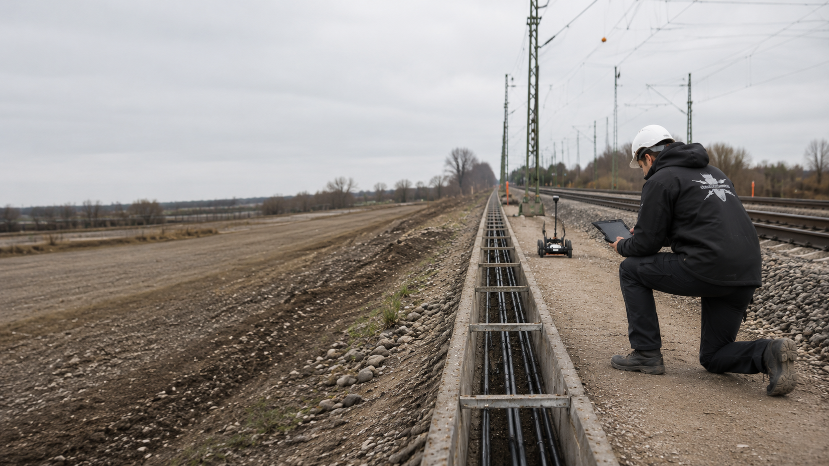
Before track renewal, formation works and new foundations, we establish which indications of ordnance are available for the areas concerned. FONTANA-EOD reviews documents, construction stage and survey conditions for the affected section. Submit the track drawing, ground disturbances and depths so that areas, borehole and foundation positions and the records needed can be specified.
Record the track, chainage and construction stage.
Specify excavation, foundations and depth.
Hand over investigated areas with clear references.
Before track renewal, formation works or new foundations, the evidence of ordnance is related to the planned ground-disturbance volume. The surveying needed depends on the target object, depth, construction stage and access. Open adjoining areas, areas following an agreed removal of track superstructure and deep individual points may need separate investigations. The records identify the section actually covered and the depth investigated; changes are checked before further ground disturbance.
At track 20 in Plattling station, GPR surveying, investigations during construction and subsequent volume clearance were combined. The report explains the sequence and spatial limits of the works. View project details. Sequence and survey images from Plattling.
Service areas:Surface surveys: GPR, TDEM and magnetometryMethod used in this project: Ground-penetrating radar
The records for railway track works between Offenburg and Niederschopfheim document 19,767 m² of surface radar surveying and seven project days. View project details.
Service areas:Surface surveys: GPR, TDEM and magnetometryMethod used in this project: Ground-penetrating radar
Track construction is not a uniform working volume. Track superstructure, cable corridors, switch areas, foundation positions and platforms have different sources of interference, depths and construction stages.
Explosive ordnance investigation is therefore divided by construction section and actual ground disturbance.
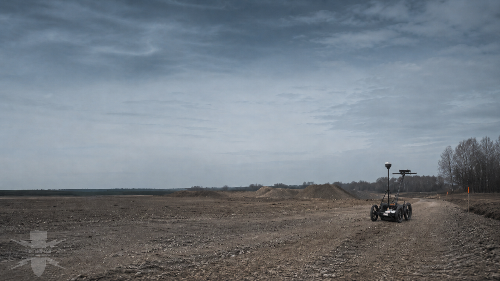
Removing rails, sleepers and ballast changes access progressively. Explosive ordnance investigation is therefore related to the demolition stage, excavation base, working width and sequence.
Preliminary investigation and supplementary measures are divided so that subsequent work begins only in clearly documented sections.
Prepare the technical scope for track renewalSwitches, point machines, cables, drainage and numerous metal installations create dense interference. Survey areas and individual ground disturbances are planned separately according to accessible subareas and the later ground disturbance.
Zones that cannot be reliably surveyed receive their own follow-up measure; a general conclusion about the entire switch area is avoided.
Assess the junction area in its project context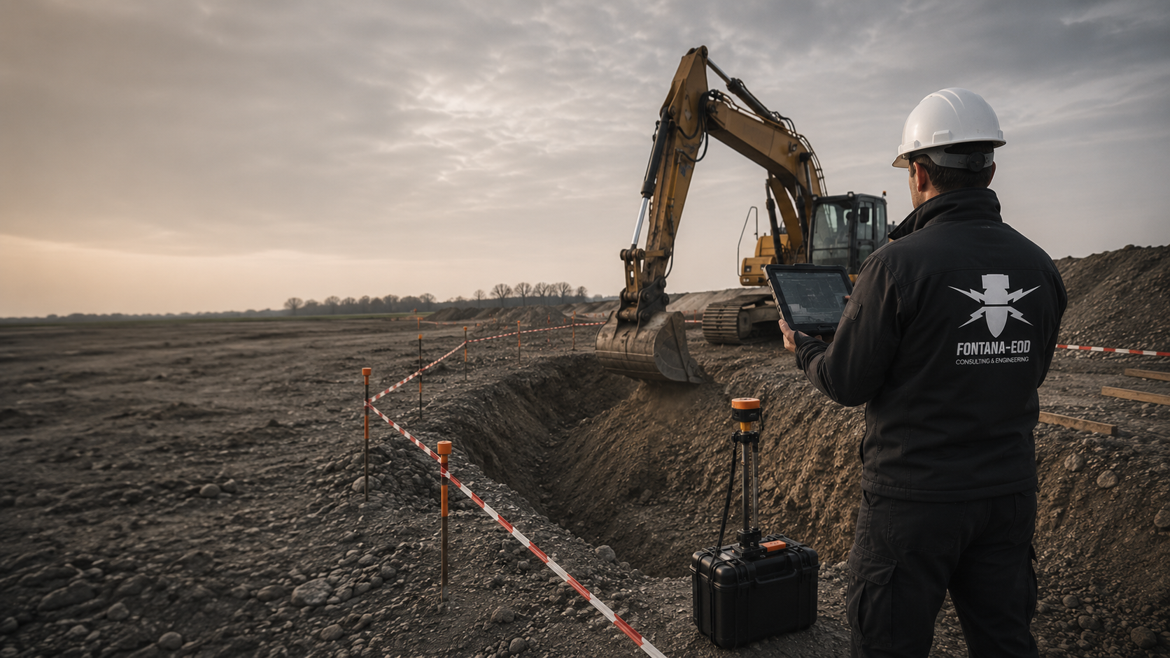
Cable trenches, crossings, chambers and drainage pipes often run through adjoining areas modified several times. Route alignment, trench width, design depth and existing utilities form the common investigation geometry.
Section surveys and excavation monitoring are documented using the same chainage references.
Coordinate cable and excavation sections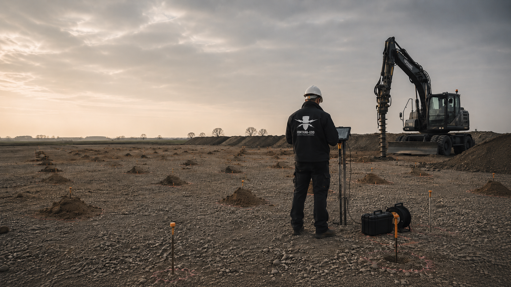
Overhead line masts, signals, noise barriers, platform roofs and technical installations require individual foundations, some of them deep. Each point is recorded with coordinates, design depth, foundation dimensions and installation method.
The deep working volume is investigated separately and not inferred from a near-surface area assessment.
Investigate foundation positions and depthPlatform edges, trackside paths, ramps, chambers and paved areas combine existing structures with utilities and changing surfaces. Method selection follows achievable survey quality and the specific demolition or new-construction section.
Zones near structures and deep individual points are assessed separately.
Define the technical scope of the platform area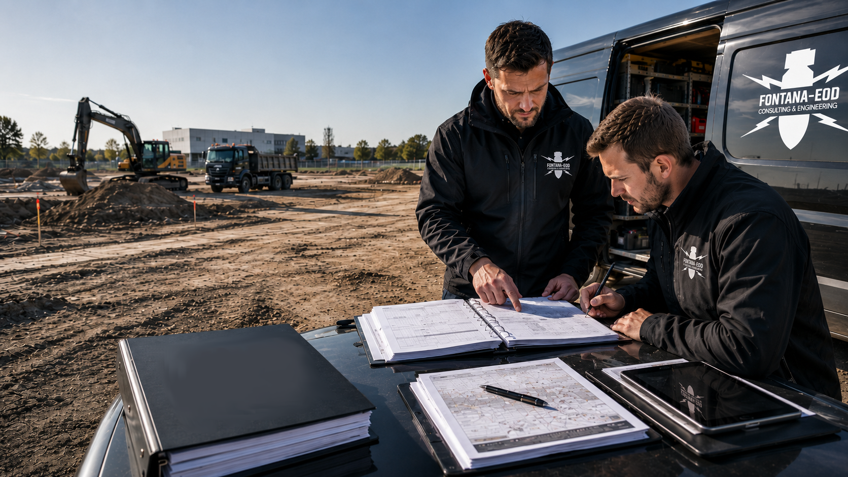
Short working windows require complete preparation of drawings, surveying and equipment. Specialist work is not shortened to fit an arbitrary time limit; it is adapted to the areas and points that can realistically be reached.
Partial handovers state investigation status, unresolved zones and conditions for the next work step.
Plan section handovers and recordsGround investigation boreholes, cone penetration tests and survey markers are often installed before the track redevelopment itself. These early ground disturbances also need clear position, depth and construction-stage references.
Borehole point lists are checked against existing utilities, track clearance, planned equipment and subsequent use. This establishes whether these early works also lie within the documented investigation area.
Investigate ground investigation positions in advanceThe appropriate service follows the project stage and actual ground disturbance. A railway section with historical indications of ordnance presents a different task from a deep mast position or ongoing formation excavation.
Explosive ordnance surveying becomes relevant in track construction where ballast, formation or underlying ground is opened, utilities installed, drainage renewed or foundations constructed and the grounds for suspicion in the actual working volume have not yet been reliably assessed.
Railway sections, planned construction stages and depths of ground disturbance are overlaid with existing ordnance evidence. Data gaps are identified early, before the option is fixed technically and in the programme.
The result identifies which sections need further historical assessment and where technical investigation must be incorporated into design.
Assess the corridor with suspected ordnance earlyService specifications, area, chainage, depth, methods, access, possessions and required documentation must use the same drawing revision. General items without section and depth references result in bids that cannot be compared.
Additional and contingent services have clearly defined triggers.
Structure the procurement documents technicallyWhile rails, sleepers and technical installations remain, survey feasibility can be severely limited. Before work begins, the adjoining areas that can already be investigated and the zones accessible only after a defined removal step are assessed.
The construction sequence records the removal step after which the additional investigation is to take place.
Coordinate removal and follow-up investigationPiles, masts, signals, anchors and ground investigation boreholes occupy point-specific depth volumes. Coordinates, design depth, diameter and installation method determine borehole spacing and survey geometry.
Relocated or additional points are checked again against the investigation volume.
Prepare deep ground disturbanceWhere utilities, ballast, reinforcement or installations limit preliminary surveying, the actual earthworks can receive specialist monitoring. Excavation layers, equipment use, stop points and reporting procedures are specified for this purpose.
Sections not monitored remain outside the assessment.
Plan excavation monitoring by sectionA survey anomaly, an object causing technical interference and a suspicious object found must be distinguished technically. Further action depends on position, construction stage, responsibilities and the agreed clearance objective.
Communication about finds and project updates are documented with positional references.
Assess the findings and recovery procedureDifferent track, chainage or coordinate references mean that survey areas, borehole positions and subsequent structures cannot be assigned reliably. Point lists, alignments and drawing revisions are therefore given a common spatial reference before tendering.
Only then can it be assessed whether existing results remain usable or relocated working volumes need fresh investigation.
Standardise the drawing revision and data referencesThe service stages are not interchangeable. Each answers its own project question and applies only to the section described, depth covered and construction stage documented.
Investigation requirements depend on construction stage, track and chainage references, depth of ground disturbance, existing utilities and which areas are technically accessible before each construction section. Rails, fastenings, cables and installations may limit individual survey methods.
Trigger: Aerial photographs, earlier documents, previous finds or official information concern a longer corridor or individual chainage areas.
Technical step: Sources are related to the current drawing revision, construction sections and ground-disturbance areas.
Required outcome: Spatially justified areas with suspected ordnance and recommendations for follow-up technical investigation.
Explore the historical baseline furtherTrigger: A section is sufficiently accessible before or after demolition and near-surface work is planned.
Technical step: The geophysical method and survey-line or grid geometry are selected according to the target object and interference.
Required outcome: Survey data recorded with geographic coordinates, limitations and a follow-up decision for the defined area.
Select surface survey methodsTrigger: Foundations, boreholes, masts or excavation supports extend below the near-surface investigation volume.
Technical step: The point list, design depth and future construction geometry are incorporated into a depth or borehole investigation.
Required outcome: A point-specific assessment with documented investigation depth and outstanding measures.
Prepare the technical design for depth investigationTrigger: Rails, cables, earthing systems and installations interfere with individual survey methods.
Technical step: Accessible subareas, other survey methods and later demolition stages are assessed separately.
Required outcome: A clear distinction between interpretable zones, zones with limitations and zones still requiring investigation.
Assess methods in the railway environmentTrigger: The ground becomes accessible layer by layer only as construction progresses.
Technical step: Each working layer is surveyed and assessed. Controlled excavation in layers and an additional visual inspection follow; these steps are repeated to the agreed base of excavation and documented.
Required outcome: Documentation by section and layer of the working volume actually investigated.
Coordinate investigation during constructionTrigger: The track alignment, foundation position, excavation depth or construction section changes after fieldwork.
Technical step: The new drawing revision is checked against the survey area, point geometry and assessment limits.
Required outcome: A clear decision on which results remain applicable and which areas need additional investigation.
Compare drawing revisions and investigation recordsTrigger: Track construction, cable civil works and foundation work need different subareas at different dates.
Technical step: Investigation boundaries, depths covered and unresolved areas are checked for each handover section and updated in the drawing and report.
Required outcome: Subsequent trades can clearly identify the areas they can use, the conditions that apply and where further investigation is outstanding.
Prepare the technical basis for subarea handoversA technical service is usable only when the drawing revision, spatial scope, survey conditions, results and assessment limits are consistent.
Documentation is updated during construction rather than assembled from individual documents only after completion.
The records remain tied to the documented section, depth investigated and construction stage covered. Design changes or additional ground disturbance are checked against that assessment before construction.
The drawing, track number, kilometre reference or chainage, construction section and coordinate system establish the spatial basis. Survey areas, borehole positions and excavation areas use the same identifiers.
Changes are updated with their date and drawing revision.
The historical assessment, official correspondence, known finds, previous surveys and project requirements are documented with their scope.
Contradictions and missing appendices remain visible as questions still needing clarification.
Track superstructure, surface, soil, moisture, utilities, earthing systems, structures, vehicles, access and operating conditions are recorded for each section.
This allows the validity of the selected method to be understood.
Raw and interpreted data, survey lines, grids, borehole positions, depths, anomalies and field logs receive clear references.
Automatic displays are supplemented by specialist plausibility checks.
Inaccessible areas, areas affected by technical interference and those beyond the investigation depth are identified spatially.
Each limitation is assigned a specific follow-up measure or remains identified as an unresolved project decision.
The report links the brief, investigation volume, methods, results, limitations and conclusion. Where suspected points are subsequently exposed or areas cleared, the findings and clearance records document the work actually carried out using the same positional references.
Designers and site management can identify which section has been investigated for the next work step and where additional work is still needed.
New track positions, revised mast positions, additional cable routes or greater excavation depths are checked against the documented survey and investigation volume. The change record identifies areas carried over, those needing additional work and those requiring new investigation.
The technical assessment remains usable across several design and construction drawing revisions.
Before each partial handover, the surface, track superstructure, existing utilities and accessible working volume are checked for consistency with the state to which the survey relates. Deviations caused by interim construction stages, newly introduced materials or revised site setup are documented.
This keeps it clear whether existing records can be used directly or need supplementing before the next ground disturbance.
The project file contains the ordnance evidence, investigation data and results for the respective construction section.
Designers and site management need these documents for procurement, section handovers and later design changes.
Aerial photographs, maps, previous uses, reports of finds and existing assessments are related to the railway line, chainage and current construction sections.
The dataset identifies which assumptions are confirmed, unresolved or need technical investigation.
Track alignments, working widths, excavation bases, borehole positions, foundations and demolition stages are documented with the respective drawing revision.
Each change is clearly related to the existing investigation status.
Survey lines, grids, raw data, interpretation, borehole logs and investigation depths remain linked by common identifiers.
Points not reached and technical deviations are described with their effects.
Anomalies are recorded by position, depth, assessment status and further measure.
Exposure or find information and the corresponding findings and clearance records are added for the work actually carried out. A survey anomaly and an object found remain distinguishable.
Equipment configuration, personnel, checks, surface conditions, interruptions and zones where data cannot be interpreted are documented.
This keeps the quality conditions actually achieved in each section identifiable.
Reports, drawings, registers, handovers and outstanding measures are brought together for designers, site management and subsequent trades.
Later construction stages can use the same dataset without extending the assessment beyond its scope.
For each section, the date, drawing revision, investigation scope, outstanding limitations and planned subsequent work are recorded. The status gives site management and subsequent trades a clear working basis without exceeding the documented scope.
When work resumes after a longer interruption, the documented state can be compared with the current construction area.
The sequence is adapted to demolition, possessions and construction stages. Results are handed to those preparing the next design or construction step.
Where construction stages take place at different times, the investigation status is checked against the current drawing, existing track superstructure and preparatory work completed in the meantime before each mobilisation. Earlier results remain usable without overlooking later changes.
The track, chainage, construction stage, working width, excavation, borehole positions and assessment required are taken from the current drawing revision.
Historical assessments, utility drawings, track superstructure, ground investigation data and earlier reports are compared spatially; data gaps are identified.
Areas with suspected ordnance are overlaid with demolition, excavation, foundations and cable routes to define the technical task clearly.
Accessible areas, deep points and interference zones each receive a suitable service and a defined investigation outcome.
Surveying, equipment, access, possessions, briefings, stop points and data transfer procedures are agreed before fieldwork.
Surveying, depth investigation or excavation monitoring take place by section; deviations are immediately related back to the brief.
Survey readings, anomalies, exposure work and limitations are assessed for technical plausibility in relation to the planned ground disturbance.
The report, drawings, registers and follow-up decision are handed over for the next construction stage and supplemented as needed when designs change.
In track construction, technical investigation must use the same spatial references as design and construction. Only then can a survey be clearly related to demolition, excavation or foundations.
A method is not selected by equipment availability alone. The determining factor is whether it can detect the expected target object within the planned working volume under actual interference conditions.
Around tracks, survey conditions often change with each removal step. Accessible adjoining areas, track-superstructure zones, deep ground disturbance and later excavation layers are therefore planned separately.
For each area, the expected assessment, technical limits and follow-up measure are specified before construction. The records identify the construction stage to which the investigation relates and which areas remain unresolved.
Survey lines and point lists are recorded not just by coordinates but also by track, kilometre reference or chainage.
Results remain linked to the construction section and future working volume.
Rails, sleeper components, fastenings, cables, earthing systems and installations can dominate survey data.
These influences are recorded before method selection and not treated as unidentified anomalies in interpretation.
The grid or profile density must suit the target object, accessible area and subsequent excavation width.
Interruptions, adjoining zones and gaps in coverage remain visible on the drawing.
Mast, pile, signal, excavation-support and borehole positions need their own spatial investigation to the intended design depth.
Surface surveys are taken into account only insofar as their documented investigation zone actually covers the point.
A section may present different survey conditions before removal of the track superstructure than after rails and ballast are removed.
Investigation is therefore distributed across defined construction stages and excavation layers rather than expressed as a general assessment for the whole site.
Cleared or investigated subareas are handed over with their drawing revision, depth and limitations.
If the alignment, width or depth changes, the new ground disturbance is checked against the documented investigation scope.
The volume considered in the explosive ordnance assessment is compared with the actual effects of the construction equipment planned. Excavator buckets, tamping and formation works, piling rigs and drilling equipment affect a spatial working volume rather than just a line.
Changing the equipment or installation method may also change the investigation volume required.

Check whether existing ordnance evidence also covers the planned side working areas, drainage and site access routes. A report for the existing track alignment does not automatically cover additional areas.
Assess the basis for suspicionFormation works, chambers and new foundation positions may require different depths. Method selection must distinguish these working volumes and compare the investigation depth actually achievable with the planned ground disturbance.
Assess depth-related investigationThe methods measure different physical properties and have their own spatial limits. A combination is useful where it addresses clearly separate tasks.
Separate services are specified for accessible areas, deep ground disturbance and zones accessible only after demolition. The assessment identifies whether surveying, depth investigation, excavation monitoring, investigation of individual anomalies or additional documents are needed.
Establishes whether historical evidence indicates possible ordnance and which railway sections are affected.
It does not locate individual objects present today and does not replace technical investigation of the planned ground disturbance.
Responds to ferromagnetic objects and requires survey areas with sufficiently low interference.
Rails, masts, reinforcement and metal installations may limit the assessment around tracks.
Records time-dependent electromagnetic responses from conductive objects.
Suitability and differentiation depend on the target object, depth, ground conditions and electromagnetic interference.
Records reflections at material and structural boundaries and can provide additional information in areas with magnetic interference.
Radar reflections do not automatically indicate ordnance; ground conditions and profile quality determine the assessment.
Investigates defined point and depth volumes for foundations, boreholes and excavation supports.
Borehole position, design depth, casing and future ground-disturbance geometry must be consistent.
Combines surveying and assessment of each working layer with subsequent controlled removal and an additional visual inspection. The steps are repeated to the agreed base of excavation; anomalies activate the defined stop points and reporting procedures.
It applies only to monitored layers and does not replace investigation outside the documented working volume.
An anomaly assessed by specialists can receive targeted follow-up within a defined working area where survey data, position, construction stage and safety arrangements allow.
Exposure resolves the point or subvolume concerned. It does not replace investigation of adjoining track sections and is documented with the finding, depth, action taken and further project decision.
The investigation must be capable of covering the planned areas and depths. Methods, execution and documentation are adapted to the respective construction section for this purpose.
Short working windows change organisation, not technical minimum requirements.
FONTANA-EOD checks historical indications against the planned investigation area and construction sequence. Early assessment identifies the areas accessible before demolition, points needing depth investigation and zones that can be investigated only during excavation.
During fieldwork, drawing discrepancies, interference conditions and areas not reached are recorded immediately. Interpretation remains tied to the survey actually carried out and the documented construction stage.
At handovers by section, site management receives a clear assessment of the volume investigated, outstanding points and conditions for continuing. This avoids extending a partial assessment to adjoining or deeper areas.
The track, chainage, construction stage, working width and depth are defined clearly before work begins.
Methods follow the target object and survey conditions; sources of interference and supplementary measures are considered before fieldwork.
Demolition, surveying, excavation and subsequent trades have defined handover points and communication procedures.
Survey lines, points, checks and deviations retain spatial references through drawings and registers.
Inaccessible areas, zones where data cannot be interpreted and those outside the investigation depth are explicitly identified.
Design changes and additional ground disturbance are checked against the existing investigation status and added with traceable records.
Removing rails or sleepers can make previously obscured areas accessible. Specify in advance which investigation should take place at that construction stage and when results are needed for the next earthworks.
The section drawing, depth information and investigation report must use the same boundaries. Unresolved adjoining zones or additional ground disturbance are explicitly assigned at handover so that subsequent work respects the documented investigation scope.
Track construction brings together client decisions, specialist design, operational coordination, construction and public-authority interfaces. Clarifying roles early prevents conflicting instructions.
Define the construction task, priorities, investigation volume, assessment required and programme references. They provide existing documents and decide on further measures.
Translates the project into track alignments, construction sections, excavation depths, point lists and construction stages and incorporates explosive ordnance investigation into design and the bill of quantities.
Set requirements for access, possessions, protection zones and operating conditions. These authorisations must be distinguished from the technical conclusion of the explosive ordnance investigation.
Implement demolition, excavation, equipment use, briefings and stop points and report changes in position, depth or construction method before construction.
Reviews documents, develops the commissioned approach, carries out the agreed specialist services and documents results, limitations and follow-up decisions.
In Germany, the ordnance disposal services of the federal states and the locally competent authorities undertake hazard response and deal with finds. Their involvement is clarified for the project location; outside Germany, local responsibilities apply.
The local public order authority and building control may be involved, depending on local procedures and the construction task. Their requirements are recorded with the location, section and current drawing revision. Technical investigation, operational authorisation and official decisions about finds remain documented with their respective contacts.
Establishes clear references linking the drawing, track, chainage, survey lines, borehole positions and as-built construction stage.
Setting-out information, as-built surveys and updated drawings are handed over so that investigation results can be compared with actual positions.
Requirements depend on the activity, project location, construction stage and regional responsibilities. The service specification, qualifications, risk assessment and documentation are therefore related to the specific commission.
In Germany, § 7 SprengG concerns the commercial authorisation for activities requiring authorisation; § 20 SprengG concerns the certificate of competence of responsible persons. Under § 1b SprengG, searching for found munitions also counts as handling them. The requirements applicable to the project depend on the activity actually commissioned.
DGUV Information 201-027 supports risk assessment and protective measures for ordnance clearance work. The Baufachliche Richtlinien Kampfmittelräumung set requirements for investigation, quality and documentation within their defined scope of federal responsibilities. Their application to the specific railway project is clarified separately.
The railway project’s operational rules are also considered. They govern access and safe work organisation but replace neither the technical brief nor the responsibilities that apply to an actual find.
The First Ordinance to the German Explosives Act (1. SprengV) includes requirements for specialist competence and state-recognised training courses. In track construction and superstructure renewal, the qualifications of responsible personnel are matched to the actual commissioned investigation or clearance scope.
DGUV Rule 113-003 concerns the dismantling or destruction of explosives or articles containing them and also includes the disposal of munitions finds. Its application follows that scope of activity and is coordinated with the respective construction section, protection arrangements and responsible interfaces.
The company, responsible personnel and specific activity must fit the permit and competence framework under explosives legislation.
Work methods, personnel, equipment, the track environment, protection zones, escape routes and communication are specified for the project.
Service limits, quality, interfaces, finds procedures and acceptance criteria are clearly specified before construction.
The investigation volume, method, results, checks, limitations and follow-up decision are brought together in traceable records.
The drawing revision, section, depth, methods, operating conditions, qualifications and required records are described in a form suitable for procurement.
Access, briefings, railway safety arrangements, surveying, stop points and reporting procedures are checked against the current construction stage.
Stop work in the affected area immediately. Do not touch or move the object. Leave the danger area and keep others away without putting yourself at risk. In Germany, contact the police immediately on 110; outside Germany, use the local emergency reporting procedure.
Results are structured by their project function. What matters is not the number of documents but their clear relationship to the track, section, depth and construction stage.
For long projects, a continuously updated status summary is also recommended, recording each section with its drawing revision, investigation date, outstanding measure and handover status.
Links the track, chainage, construction section, working width, excavation base and investigated subareas.
Design changes and handovers remain traceable in time and space.
Document section and chainage references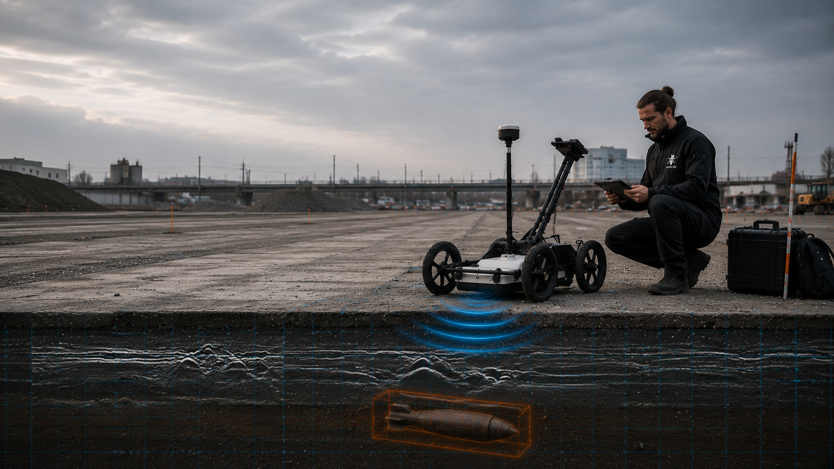
Brings together survey lines, grids, anomalies, known objects causing interference and zones where data cannot be interpreted, using clear identifiers.
Assessment status and follow-up measures are updated.
Assess survey profiles and anomaliesDocuments coordinates, design depth, borehole geometry, survey conditions, investigation depth reached and the specialist conclusion for each point.
Relocated or additional points remain identifiable.
Check borehole positions and depth referencesRecords the monitored section, excavation layer, equipment use, interruptions, observations, stop points and agreed communication.
The conclusions apply only to the working volume actually monitored.
Coordinate excavation and specialist supervisionShows areas with no access, technical interference, insufficient data depth or an outstanding follow-up measure.
Site management can then resolve outstanding points specifically before the next ground disturbance.
Document unresolved areas and assessment limitsBrings together initial conditions, the service, investigation volume, data, results, limitations and the next decision.
It provides a common basis for design, procurement, site management and later updates.
Organise the section report and project fileSummarises the drawing revision, section handed over, underlying reports, remaining limitations and agreed conditions for the next work step.
The note facilitates practical site coordination without extending the technical scope of the underlying investigation.
Agree handover documents together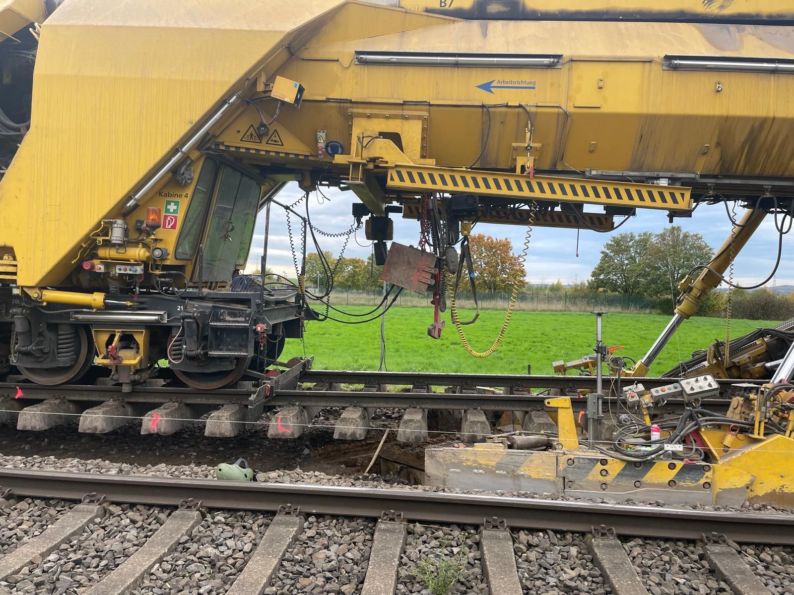
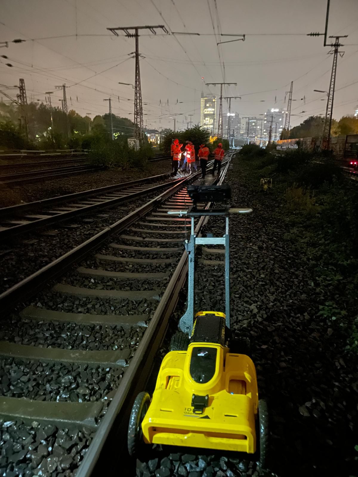
Assess the overall railway and route context alongside other specialist tasks and interfaces.
Assess the railway project in its overall contextEstablish the spatial basis for sections with suspected ordnance and priorities before technical surveying.
Clarify historical suspicion indicators
Compare magnetometry, TDEM and GPR by target object, surface and interference.
Select a suitable area survey methodPrepare mast, pile, excavation-support and borehole positions with their own investigation geometry.
Investigate deep ground disturbanceIncorporate zones that cannot be fully investigated in advance into the actual earthworks process.
Plan excavation monitoring by section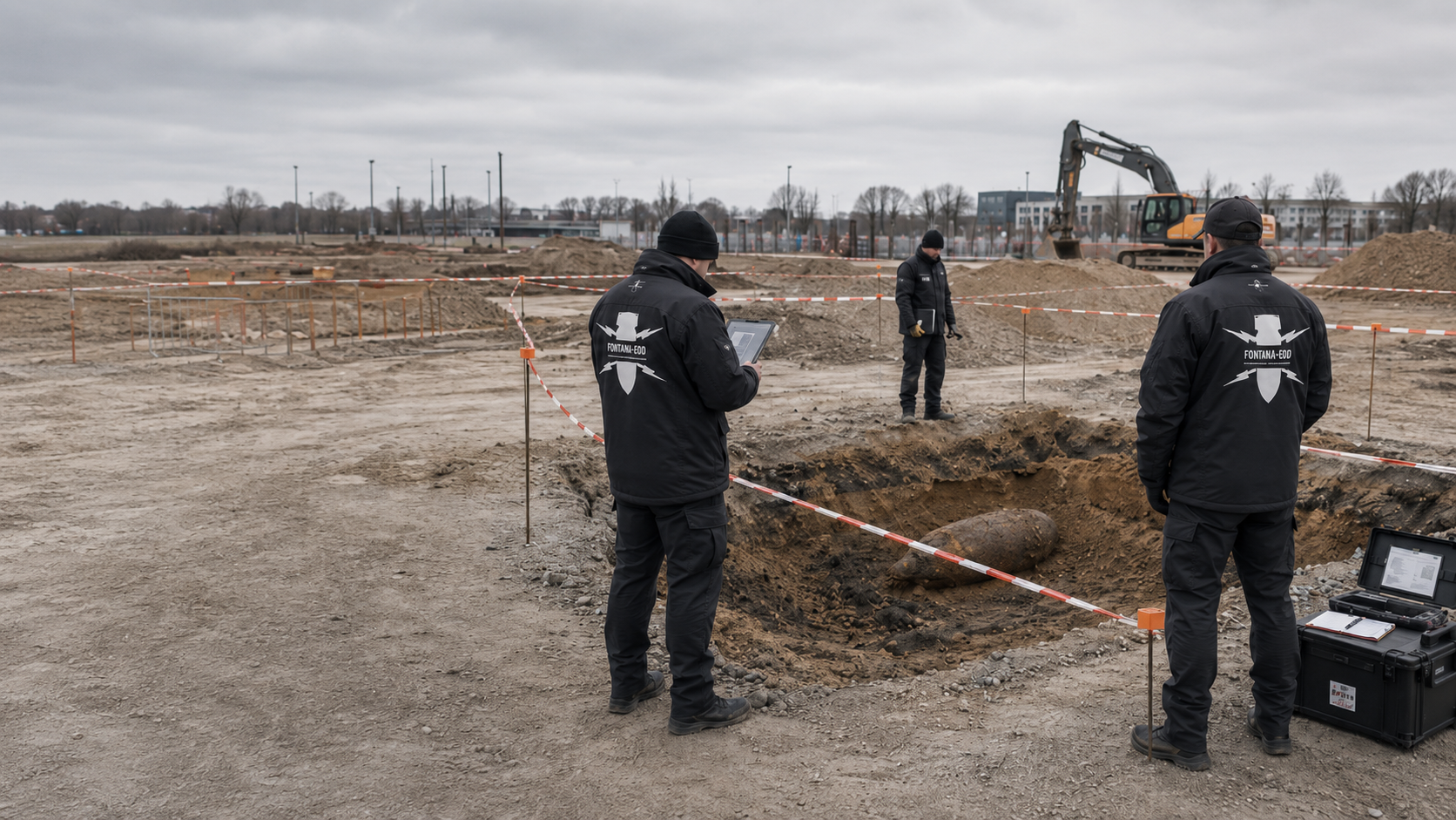
Assess the handling of findings, responsibilities and handover following a confirmed find.
Clarify reporting and recovery arrangementsStructure bills of quantities, quality assurance, reports and section handovers.
Prepare procurement and project recordsHave the track drawing, construction section, ground disturbances, possessions and available documents technically reviewed.
Enquire about a track construction project and submit documents
Location references include the project location, railway line, track, chainage and construction section. Also mark side construction areas and access routes. Existing requirements are assigned to their actual section and checked again when designs change.
After ballast removal or formation changes, depth information may have a different reference level. The report and construction drawing must identify the surface from which measurements were taken and the depth reached by the next work step.
Check evidence against the interventionA wider trench, additional chamber or relocated foundation changes the ground-disturbance volume. Check the change against existing results before construction and clearly assign the investigations still needed.
Explore the technical principlesTechnical information
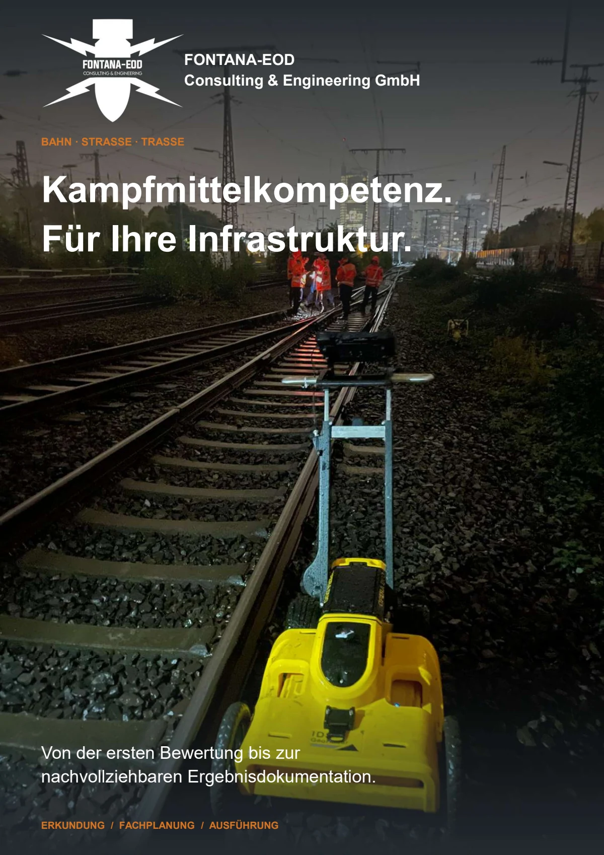
The brochure shows how FONTANA-EOD combines historical investigation, specialist planning, surveying and construction supervision in infrastructure projects. It explains trackside constraints, method selection and limitations, and result documentation.
Especially in multi-year construction programmes, existing investigation results should be checked against the current drawings and construction stage before further work. Earlier investigations remain reliable only within their documented spatial and technical scope.
Technical assessment should begin as soon as the track alignment, construction section, anticipated depth of ground disturbance and construction method are identifiable. Historical assessment and area definition can be prepared at early design stages. Before tendering and construction, survey areas, deep ground disturbance, inaccessible zones and the required records must be related to the current drawing revision.
Railway line and site drawings with track references, kilometre references or chainage, construction sections, existing track superstructure and utilities, planned excavation depths, borehole and foundation positions, and existing aerial photograph assessments and previous survey reports are essential. Construction stages, possessions, access and the decision or investigation outcome required are also needed.
Existing requirements and official information are submitted with all appendices, dates and spatial scope. In Germany, the involvement of the relevant KBD, KMBD or KRD and local public order authority is clarified for the project location; operational work authorisations remain separate. Outside Germany, coordination is with the authorities responsible locally.
Usually not. Rails, sleepers, fastenings, cables, earthing systems, masts, structures and changing surfaces affect survey feasibility. Accessible near-surface areas, deep borehole positions and zones reached only after demolition present different tasks. Suitable methods and alternative measures are therefore combined by section and ground disturbance.
It becomes relevant where piles, masts, signals, sheet piles, anchors, ground investigation boreholes or other deep ground disturbance are planned. The determining factors are coordinates, design depth, diameter, installation or drilling method and the actual working volume affected. A near-surface survey does not automatically cover this depth volume.
Zones affected by technical interference, inaccessible areas and those reached only after demolition are marked spatially and are not assessed as being without anomalies. Depending on the construction stage, additional geophysics, point-specific depth investigation, controlled exposure or agreed excavation monitoring may be appropriate. The follow-up measure is specified before the ground disturbance concerned.
It can be used where a complete preliminary survey is prevented by track superstructure, utilities, structures or extensive technical interference. Monitoring is limited to defined excavation layers and sections. Equipment use, stop points, instruction channels, communication about finds and documentation are agreed with site management and the contractors.
Each working layer is surveyed and assessed by a specialist before removal. Controlled excavation in layers and an additional visual inspection follow. This sequence is repeated to the agreed base of excavation; merely watching the excavator does not replace it.
If an unexpected object suspected of being ammunition is encountered, work stops. Do not touch it, move it or expose it further. Leave the immediate area and warn others without putting yourself at risk. In Germany, contact the police on 110; outside Germany, follow the local emergency reporting procedure. The competent authorities determine further action; a project enquiry does not replace reporting the find.
Usable records link the drawing revision, track and chainage references, areas or points investigated, methods, survey conditions, results, limitations and follow-up decisions. Anomaly lists, borehole logs, section drawings and field reports must use the same identifiers. The conclusion applies only to the documented investigation scope.
The determining factors are section length and width, number and depth of individual ground disturbances, condition of the track superstructure, utilities and interference, access, possessions, methods, surveying, data quality and documentation scope. The number of construction stages and additional measures required also has an effect. A reliable estimate therefore needs clear location and ground-disturbance references.
An initial enquiry does not need to contain a complete bill of quantities. It should show where work is planned, the existing construction stage and the proposed ground disturbance.
Incomplete documents are also useful because they identify questions still needing clarification.
For multi-stage construction programmes, also state which areas are used only temporarily, which points need early investigation and which decisions depend on a later demolition stage. This prioritisation allows technically sound subdivision into sections and prevents provisional design assumptions from being treated as the final investigation volume.
Provide the railway line, track, kilometre reference or chainage, drawing revision, working width and construction sections affected. Crossings, structures, switches, platforms and inaccessible zones should be identifiable on the drawing.
Describe removal of track superstructure, formation works, cable trenches, drainage, boreholes, piles, masts, excavation support or other ground disturbance with maximum depth and construction method. State possessions and working windows.
Include existing historical assessments, official correspondence, utility and as-built drawings, ground investigation data, previous survey reports and findings records. State whether the result is needed for design, tendering, site management or the project file.
Across several construction or procurement packages, mark work-package boundaries, handover points and shared working areas on the drawing. This avoids survey areas falling between two responsibilities or the same area being described using different drawing revisions.
Also identify temporary haul roads, crane standing areas and storage areas where relevant ground disturbance or foundations are planned.
For an initial assessment, a track or site drawing, chainage, short description of ground disturbance, maximum depth, construction stage and existing indications of ordnance are often sufficient.
FONTANA-EOD then identifies the information still needed and the technically appropriate service area.
Track, chainage, construction section, working width, structure and drawing revision.
Point list, coordinates, design depth, diameter and installation or drilling method.
Possessions, access, demolition sequence, parallel trades, stop points and handover dates.
Documents for design, procurement, site management, operator communication or the project file.
Whether historical aerial photograph analysis, explosive ordnance surveying, surface surveying using GPR, magnetometry or TDEM, deep-ground surveys, downhole surveys, excavation supervision, area clearance or ordnance recovery is needed depends on the location, ground disturbance, depth, ground and existing documents. An early ordnance assessment provides clarity for tendering, programming, occupational safety and construction.
FONTANA-EOD combines its Section 7 SprengG licence, specialists holding Section 20 SprengG certificates of competence, suitable survey and clearance methods, and traceable documentation. Send the site plan, depth of ground disturbance, construction phase and existing documents for an initial technical assessment.


