Project pathway
The quickest route to the right decision.
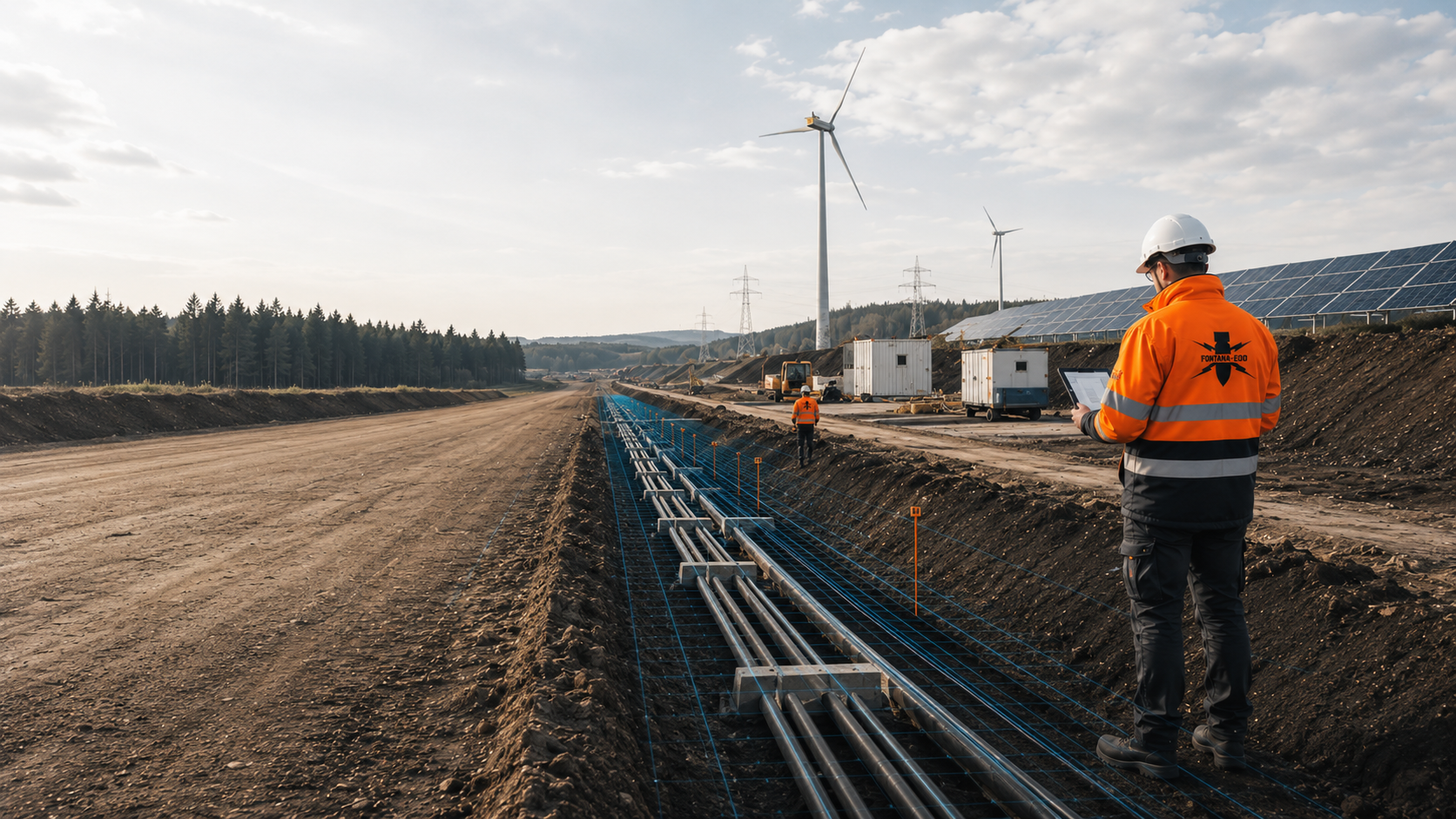
For utility corridors, energy installations and network hubs, we establish the available ordnance indicators and investigation results before groundworks. FONTANA-EOD plans suitable ordnance investigations according to location, construction depth, method and access. Send route and installation plans, intervention depths and construction phases so that services and evidence for trenches, crossings and foundations can be defined before the relevant groundworks.
Structure the route, area and installation points.
Distinguish trenches, boreholes and foundations.
Document sections and points unambiguously.
Before trenching, drilling and foundation work, existing suspicion indicators and planned interventions are used to establish which ordnance investigations are needed. Route sections, crossings, stations and installation areas are considered by position, depth and construction method. Each area is assessed to determine which historical investigation, surface or deep-ground survey or construction-phase investigation is technically suitable. Results and unresolved zones are assigned to the relevant plan revision and construction section.
The scope of services for “Saarbrücken – DB transformer station / maintenance facility – Lot 3 Saarbrücken / Germany” included downhole magnetometry.
Service period: 2026-09
Service areas:Downhole magnetometry / deep-ground survey
View project details · Deep-ground and downhole surveys · Project location: Saarbrücken
Service period: 2024-08
Service areas:Downhole magnetometry / deep-ground surveySurface surveys: GPR, TDEM and magnetometryMethod used in this project: Ground-penetrating radar
View project details · Deep-ground and downhole surveys · Region: Rhineland-Palatinate
View project details · GPR and limitations · Region: Rhineland-Palatinate
References from project practice
Utility and energy projects involve investigation of routes, foundations and individual intervention points. The map leads to our published references from these project settings.
Project information is loaded from the reference list.
Select a project location from the place selector or choose a point on the map.
The markers show official place centres. The associated references state the construction task, services performed and documented scope.
Map data: © GeoBasis-DE / BKG (2026), VG250 / GN250 / DLM250, dl-de/by-2-0; Luxembourg: ACT / data.public.lu, CC0. Geometries projected and simplified for display.
Each project type has its own combination of area, line, point and depth. Select the specialist field matching the planned construction and work volume.
Combined projects are structured by work volume rather than project name. A wind farm may, for example, include access roads, cable routes, substation equipment and storage; each element has its own interventions and evidence limits.
Fibre-optic routes combine open trenches, trenching, directional drilling, chambers, distribution units and property connections.
Investigation results are assigned to the relevant corridor, construction method, depths and rollout section. Property-connection lots, POP sites and short-notice route revisions use the same section and point identifiers so that field services and civil-engineering crews work from an unambiguous data set.
The rollout is structured by deployment cluster and construction method so that open trenches, crossings and network hubs are not combined under a generic route statement.
Assess the fibre-optic rolloutSolar farms include posts, transformer stations, cable trenches, access roads, storage and assembly areas across large sites.
Area assessment and individual depth volumes are linked by construction section and foundation type. Construction roads, inverters, storage options and drainage areas are also included where relevant ground interventions or load transfer are planned.
The installation area, driven or screw-in points, cable trenches and transformer sites receive separate investigation geometries and a shared project status.
Assess the solar farm and construction areasWind-energy projects combine deep foundations, crane pads, access roads, cable routes and geotechnical boreholes.
Each turbine position receives its own area, point and depth references for design and execution. Temporary assembly areas and permanent installation areas are documented separately because their interventions, depths and later uses differ.
Foundation, crane pad, access road and internal cable route are coordinated so that deep and area-wide work volumes remain unambiguous.
Assess the wind farm and turbine sitesUnderground cable projects consist of long corridors, joint bays, crossings, site-establishment areas and storage areas.
Chainage, trench geometry, ground intervention and sectional handover determine the ordnance assessment. Joint locations, crossing structures and varying laying depths receive their own identifiers so that the route assessment remains reliable through plan revisions and procurement by section.
Standard trenches, joint bays, crossings and construction roads follow the same chainage but are assessed using distinct methods.
Assess the power route and underground cablesPipeline construction includes pipe trenches, jacking works, welding areas, valve stations, access roads and temporary work strips.
For pipe trenches and individual structures, investigation areas are described with depth, working width and construction method. Launch and reception pits, valve locations and deep drilling corridors are not inferred from the general pipe-trench investigation but assessed as separate work volumes.
Work strips, pipe trenches, valve points and trenchless crossings each receive their own area and depth references.
Arrange specialist assessment of the pipeline corridorDistrict-heating routes often run through dense road and utility networks and require deep excavations in sections.
Existing services, trench support, chambers and property connections are checked against each construction phase. Traffic arrangements, trench support and short work cycles are coordinated early with ordnance assessment so that zones that cannot be measured are clarified before each excavation.
Dense existing services and sectional excavations require early coordination of utility information, measurability and excavation arrangements.
Prepare the district-heating routeWater and wastewater projects range from utility trenches and chambers to inverted siphons and crossing structures.
Invert levels, sewer reaches, excavations and inaccessible sections receive separate evidence. Sewer reaches, chambers, pump connections and crossings remain linked unambiguously through invert level, chainage and construction section.
Chambers, sewer reaches, utility trenches and crossing structures are assessed according to invert level, construction condition and actual access.
Assess the water and wastewater routeSubstations combine area-wide installation zones with foundations, cable basements, gantries, earthing and incoming connections.
Operating conditions, the metallic environment and deep point interventions are considered before method selection. Cable basements, gantry foundations, transformers, operating roads and later expansion areas are included according to their construction and operating conditions.
Metal installations, earthing and existing assets can limit area measurements; the depth volume for foundations and gantries is considered separately.
Assess substations and transformer positionsStorage projects require installation areas, container foundations, transformer equipment, cable trenches and fire-safety distances.
Area, utility and foundation zones are assessed separately and combined for installation design. Container rows, transformer points, firefighting-water installations and cable feeds are planned as separate area and point tasks and then combined in a shared installation file.
Storage containers, transformers, cable routes and assembly areas are related to the current installation design and intended foundation.
Arrange specialist assessment of the storage siteComparing options requires different documents from tendering or imminent excavation.
Linear projects also include access roads, storage and assembly areas, intermediate storage, construction roads and temporary structures where ground intervention occurs. These ancillary areas may lie outside the actual route corridor and therefore need their own spatial assignment.
Historical indicators, known finds, uses and existing information are related to route options and installation sites.
The assessment supports comparison and prioritisation of options without anticipating the technical investigation of the later intervention.
The early assessment shows which options could require additional investigation or clearance.
Compare suspected corridorsAlignments, work strips, chambers, pits, foundations, access roads and construction phases are translated into specific ground interventions.
Data gaps, inaccessible areas and technical interference zones are identified before quantity and schedule planning.
Plan changes are checked for their effect on corridors and point lists already investigated.
Assess the design stageAreas, lengths, depths, methods, preparatory services, qualifications and evidence must remain comparable across lots and contractors.
Provisional items receive a clear trigger and an unambiguous spatial basis for quantities.
Consistent data formats and acceptance criteria support project-wide status and quality control.
Define the services and procurement basisStandard trenches, assembly areas, installation fields and access roads are assessed by surface, ground and interference environment.
The measurement method must match the planned excavation depth and actual working width.
Measurement conditions and depths are documented for individual sections even when they are commissioned together.
Select area and trench assessmentCrossings, pylons, piles, anchors, chambers and geotechnical investigations require examination of the future depth volume.
Coordinates, target depth, diameter, direction and installation method provide the technical basis.
General area evidence does not automatically cover deep or inclined work volumes.
Assess deep spaces affected by the worksExisting assets, traffic, operating installations and strong interference fields may restrict advance assessment.
For areas not sufficiently investigated, suitable additional methods and possible access after demolition or exposure are assessed. Necessary investigations and protective measures are planned before ground interventions during breaking out, demolition or creation of access.
Where construction-phase ordnance surveying is technically suitable, each working layer is technically surveyed and assessed. Controlled layer-by-layer removal and supplementary visual inspection follow; these steps are repeated down to the agreed excavation bottom. Excavation layers, stop points, authority to give instructions, communication channels and documentation are defined before work begins. Merely watching the excavator remove soil is not sufficient.
Coordinate construction conditions and excavationThe suitable investigation depends on planned ground interventions and local measurement conditions. Areas, lines, points and depths are therefore assessed separately and combined in a shared status.
The assessment follows the current project decision. Preliminary design focuses on spatial prioritisation, whereas before construction, specific measurement areas, point lists, target depths and inaccessible areas must be defined unambiguously.
Initial situation: The route or installation site lacks a reliable spatial basis for suspicion assessment.
Technical step: Historical sources and existing information are related to options, construction areas and priority sections.
Documentation objective: Suspected areas, data gaps and priorities remain linked to the corridor and plan revision.
Establish the historical basisInitial situation: An open trench or work strip has a clearly defined width and depth.
Technical step: Target object, soil, surface and interference environment determine the suitable linear or area-wide method.
Documentation objective: Measurement coverage, interference zones and statement limits are related to chainage and subsequent excavation depth.
Assess the route section’s method requirementsInitial situation: Utilities, earthing, steel, reinforcement and operating equipment affect measurement data.
Technical step: Achievable conclusions, sub-areas and additional methods are defined before fieldwork.
Documentation objective: Interpretable and restricted zones are shown separately. Suitable further action is defined for unresolved areas.
Assess the installation area and interference environmentInitial situation: The future work volume extends below the reliably investigated near-surface zone.
Technical step: Point, alignment or borehole geometry is investigated at depth according to position, target depth and installation method.
Documentation objective: Point and depth evidence can be transferred directly to borehole, pylon, pile or structure lists.
Investigate the geometry at depthInitial situation: Existing assets, traffic or a structure prevent sufficient investigation before execution.
Technical step: It is assessed which demolition stage permits suitable measurement access and whether additional methods are needed.
Documentation objective: Investigated layers and areas not dealt with are recorded traceably for site management and subsequent trades.
Prepare excavation and exposureInitial situation: Measurement data or construction work indicate a need for further clarification.
Technical step: measurement anomalies are interpreted by specialists. If an unexpected suspicious object is found, work stops immediately and the competent authorities are notified without delay.
Documentation objective: Findings, processing and remaining action requirements are updated in the project file with precise location references.
Clarify the findings and handover processUtility and energy projects need documentation that connects long corridors, individual structures and phases separated in time within a consistent structure.
For corridors crossing federal-state, district or municipal boundaries, regional documents and responsibilities are maintained within a shared project structure. This keeps clear which statement applies to which section and local procedural stage.
Route alignments, installation areas, work strips, point lists, construction sections and plan revisions provide the spatial reference.
Coordinate systems and identifiers are used consistently in design, fieldwork and reports.
The geometry structure supports links with GIS, construction progress and operator documents.
Historical assessments, information from authorities, old documents and known finds are documented with their scope.
Unresolved sources and contradictory statements remain visible as specific clarification tasks.
Historical assumptions, technical measurements and actual finds remain technically distinct.
Measurement system, grid, lines, investigation depth, surface, soil, access and interference sources are recorded by section.
For drilling and excavation, point geometry, casing, layers and construction equipment are also included.
Acquisition conditions form part of the assessment and therefore of subsequent usability.
Measurement lines, borehole positions, anomalies, exposures and field observations receive unique identifiers.
Data, maps, lists and records must cross-reference one another.
A consistent register supports quantities, quality control and handovers across multiple lots.
Inaccessible zones, zones affected by technical interference and zones outside the investigation depth are identified spatially.
The required follow-up service is defined for each area before intervention.
Unresolved zones receive a specific spatial task rather than a general reservation.
The report describes the area, linear and depth volumes actually dealt with and the project status achieved.
Later plan changes and additional points are checked against this status.
The conclusion remains limited to the documented scope of work.
The sequence is adapted to design maturity, approval, construction method and section priorities. Investigation results must be available in good time for each construction section.
Ordnance assessment is coordinated with approval, procurement and construction schedules. Preparatory services and decision dates are prioritised so that fieldwork does not begin only after civil-engineering crews have mobilised.
Route, installation, structures, depths, construction phases and required decisions are taken from the current plan revision.
Areas, lines and points are maintained within a shared project structure.
Historical assessments, information from authorities, utility data, geotechnical documents and earlier reports are organised.
Missing information receives a specific acquisition or clarification task.
Work strips, trenches, crossings, foundations, chambers, boreholes and assembly areas are described unambiguously.
Different construction methods are not grouped under a generic investigation depth.
Historical assessment, surface surveys, deep investigation and excavation supervision are combined according to the work volume.
Methods are selected according to technical suitability and the conclusion required.
Access, surveying, traffic or operating conditions, equipment, stop points and data flows are coordinated.
Short construction windows are prepared organisationally without reducing technical quality.
Measurements, point assessments and construction-phase services are carried out with location, chainage and section references.
Inaccessible areas and deviations are documented immediately.
Anomalies, restrictions and deviations from the plan are checked for plausibility against the suspicion basis and construction geometry.
An anomaly is not classified as ordnance or a harmless installation without specialist assessment.
Reports, maps, status lists and outstanding measures are prepared for designers, site management and operators.
New plan revisions and additional interventions are checked against the documented scope of work.
Linear, area-wide and point interventions are recorded separately in space for the investigation. A shared plan revision connects these details without treating different depths and installation methods as uniform.
A line on a route plan alone describes neither the working width nor the whole ground volume. Trench cross-section, slope, retaining works and lateral work areas supplement the alignment. For crossings, launch and reception pits and the three-dimensional path between them are shown.
Installation areas are supplemented by foundations, chambers and cable spaces. Deep or inclined elements include the starting position, direction and final depth. Specialist planning compares these geometries with the investigation volumes that can be reached and the actual interference.
The report and execution design use the same position and height references. After a plan change, it is checked which results still match the intended intervention and which areas need to be considered anew.
Chainage, lateral boundaries and the intended trench shape describe the utility corridor. Additional excavations and temporary work areas are recorded with their own positions.
Target depths refer to a clearly identified ground or working level. Excavation and fill can change this reference and must remain identifiable in the comparison.
The site plan and depth profile show the launch pit, reception pit and planned underground alignment. Investigation results for the pits are not automatically transferred to the entire crossing.
Point identifier, dimensions and installation method distinguish individual foundations. Deep structural elements are stated with their three-dimensional path and required work volume.
Utilities, installations and operating areas may restrict access and measurement quality. The sequence states when restricted areas will become accessible and what additional work will then be needed.
Changed alignments, additional points and new depths receive unambiguous references. The current report shows volumes dealt with and outstanding tasks using the same identifiers as the design.

Utility routes, crossings and installation sites are checked against the same historical basis. Temporary access roads, excavations and lateral work strips are included where ground intervention occurs.
Assess the basis for suspicion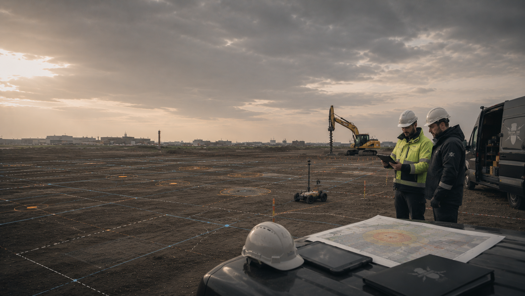
The choice between surface investigation, deep-ground surveying and construction-phase work follows the geometry and actual measurement conditions. A method for an open corridor cannot be transferred to a deep foundation or concealed crossing without assessment.
Select methods for areas and construction conditionsCharging points, overhead-line pylons, joint bays and pumping stations have their own construction and depth geometries. Sites, utility connections and foundations are shown on the site plan with their actual work volumes.
Charging points, transformer stations, cable routes, canopies and traffic areas create different intervention depths. The investigation scope and required evidence are defined for sites, utility corridors and foundations.
Pylon sites, temporary arrangements, access roads and geotechnical boreholes are individual deep points distributed along long routes. Coordinates, foundation type and target depth are maintained in an updatable point register.
Cable routes combine standard trenches with deep joint structures, crossings and temporary assembly areas. The evidence distinguishes linear route sections, individual pits and changed construction conditions.
Pumping stations and pressure pipelines combine excavations, chambers, foundations, utilities and operational interfaces. The structure, route and deep points are planned within a shared location and documentation structure.
Designers, field teams and site management use the same area, chainage and point identifiers. Before execution, the plan revision, investigation results and outstanding tasks are compared.
For operators and project management, it is particularly important that technical conclusions, construction progress and the current plan revision remain aligned. Changes are therefore not merely noted in text but related back to areas, lines and points in the existing progress record.
FONTANA-EOD starts with the actual intervention. A standard trench, HDD crossing, pylon foundation, wind-turbine site and substation area need different investigation volumes. These differences are considered during document review and service specification.
During design and execution, changed alignments, additional points, new construction conditions and technical restrictions are checked against existing progress. This establishes which existing results remain usable and where additional work is needed.
Measurement anomalies are communicated with precise locations and their underlying data. Known technical installations, unclear interfering objects and uninterpretable zones receive specialist assessment and suitable follow-up investigation. If an unexpected suspicious object is found, work stops immediately and the competent authorities are notified without delay; internal coordination must not delay the report.
Project management receives a reliable status for each section and point, not a blanket statement for the entire corridor. This supports prioritisation, partial handovers and specialist assessment of later changes.
Route, area, point, depth and construction condition are defined before fieldwork.
This prevents different services from being combined in an unclear overall item.
Target object, soil, surface and interference environment determine the technical service.
Methodological limits are incorporated into project planning before execution.
Measurement data, borehole positions, excavation, findings and reports use the same identifiers.
Spatial consistency supports quality review and data handover.
Plan changes and additional interventions are related to existing results.
Earlier statements are not transferred to new geometries without review.
Inaccessible or technically restricted areas remain visible spatially.
Each restriction receives a technically justified follow-on decision.
The conclusion answers the project question and identifies outstanding measures.
Progress remains tied to the documented area.
Network operators, project sponsors, designers, contractors, specialist companies and public authorities have different tasks. For plan changes, section handovers and finds, it must be clear who is informed and who takes on each task.
Large network-expansion programmes may involve several clients, design lots and civil-engineering contractors at the same time. Shared identifiers, named contacts and agreed handovers help track unresolved areas and findings across lot boundaries.
Defines the project objective, corridor, installation sites, priorities and required conclusion.
Provides existing documents and sets the overall project organisation.
Where several project sponsors are involved, responsibility for maintaining the shared data and progress record is defined.
Translates the project into work strips, alignments, depths, pits, foundations and construction phases.
Integrates ordnance assessment and evidence into design, approvals and tendering.
Plan revisions must show which geometry is intended for execution and which is only for comparing options.
Arrange access, operations, electrical isolation, protective zones and conditions of use.
Changes to installation or operating conditions are communicated before fieldwork.
Operational permission and ordnance investigation progress remain separate decisions.
Implement work areas, depths, equipment, instruction and stop points.
Report changed alignments, additional points and unforeseen obstacles.
The actual construction condition is checked against the documented investigation area.
Assesses documents, suspicion and methods and performs the agreed specialist service.
Documents the scope of work, results, limits and follow-up measures.
The commissioned specialist company prepares technical information and project communication; hazard-response decisions follow the local allocation of responsibilities.
In Germany, the ordnance disposal services of the federal states and the locally competent authorities carry out hazard-response and find-management duties. Their involvement is established for the project location; outside Germany, local responsibilities apply.
The specific authority and its designation vary by region.
The local public-order authority and, where relevant, the building-control authority are involved in their project-specific roles. Requirements and contacts are assigned to the actual route sections or installation sites; reporting procedures are defined before work begins.
Requirements depend on the activity, project location, construction method, installation condition and find situation. Qualifications, risk assessment, service specification and documentation are defined for the project.
Operational, access-route and approval requirements are coordinated with the ordnance task. The determining factor remains the ground intervention actually planned; operational or construction permission does not replace specialist assessment of the affected ground volume.
In Germany, § 7 SprengG concerns the commercial authorisation for activities requiring authorisation; § 20 SprengG concerns the certificate of competence of responsible persons. Under § 1b SprengG, searching for found munitions also counts as handling them. The requirements applicable to the project depend on the activity actually commissioned and the allocation of responsibilities.
The risk assessment considers methods, personnel, equipment, traffic, installation operation, electrical or technical equipment, protective zones, escape routes and communication. For long routes, it must be applicable to changing sections and construction conditions.
DGUV Information 201-027 supports risk assessment and protective measures for ordnance clearance work. The Baufachliche Richtlinien Kampfmittelräumung contain requirements for historical and technical investigation, clearance planning, procurement and documentation within their defined remit for the German federal government. Their application to the specific utility or energy project is established separately.
If an unexpected suspicious object is found, stop work in the affected area immediately. Do not touch, move or uncover the object further. Leave the danger area and keep others away without putting yourself at risk. In Germany, notify the police immediately on 110; outside Germany, use the local emergency reporting procedure. The competent authorities determine what happens next. Then inform project management.
The First Ordinance to the Explosives Act (1. SprengV) includes requirements for specialist knowledge and state-recognised training courses. In utility and energy construction, the required qualification is determined by the investigation or clearance scope actually commissioned.
DGUV Rule 113-003 concerns the dismantling or destruction of explosives or corresponding objects and also includes the disposal of found munitions. It applies according to this field of activity; it does not replace a risk assessment specific to the planned ground intervention.
Companies, responsible persons and specific tasks are assigned appropriately for each work step of the infrastructure project.
Measurement, exposure, clearance and recovery may trigger different requirements.
Construction methods, installation operation, traffic, personnel, equipment, protective zones and communication are considered together.
Changes to work or operating conditions are checked against the protective arrangements.
Areas, lengths, points, depths, methods, preparatory services and evidence are described unambiguously.
Provisional items receive a technical trigger and a verifiable quantity basis.
Route status, measurement data, findings, restrictions and follow-up measures are maintained within a consistent handover structure.
The technical statement remains tied to the section, plan revision and documented intervention geometry.
The suspicion basis, project geometry, qualification requirements and contractual evidence are defined.
This makes offers technically comparable and clarifies interfaces with construction, operations and subsequent trades.
Responsible persons, work areas, instruction, stop points and plan changes must be known.
Progress is related to the current section and actual construction condition.
Stop work immediately, do not touch, move or uncover the object further, leave the immediate area and keep others away without putting yourself at risk. In Germany, notify the police immediately on 110. Outside Germany, use the local emergency reporting procedure.
Further action depends on the find situation and regional responsibilities.
Plans, measurement data and field records must represent both long corridors and individual installation and foundation areas. Their assignment is retained through design, construction and later updates.
In addition to individual evidence, the project receives a status overview distinguishing completed, restricted and unresolved work volumes. This overview supports coordination between network operators, designers, site management and subsequent trades.
The overview connects the route corridor, structures, foundations, crossings and construction phases with their respective progress.
Select the appropriate route and installation type
The mapping shows supported suspected areas and data gaps as a basis for further investigation.
Review historical evidence of suspected ordnance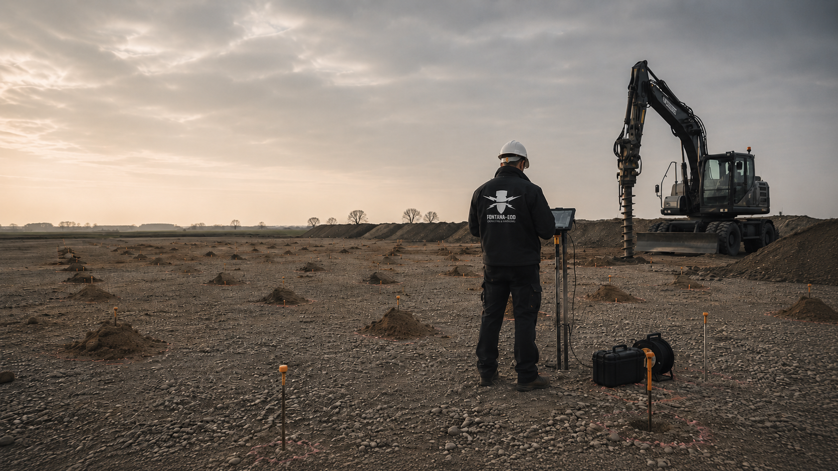
Depth evidence applies to the documented work volume and the installation method considered.
Investigate deep points and crossings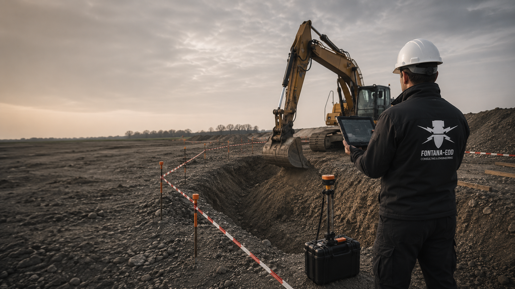
The suitability of construction-phase ordnance surveying is assessed for each excavation layer. The documented investigation area limits the statement’s scope.
Arrange specialist supervision of excavation in the route section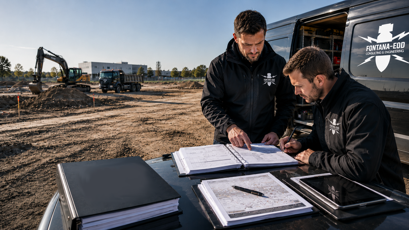
The project file distinguishes measurement anomalies, technical interference objects, actual finds and outstanding measures.
Document findings and outstanding measures traceably
The final report describes the initial situation, investigations, technical limits and further steps required. After actual exposure or clearance work, the corresponding findings and clearance records are included.
Connect the project file and final report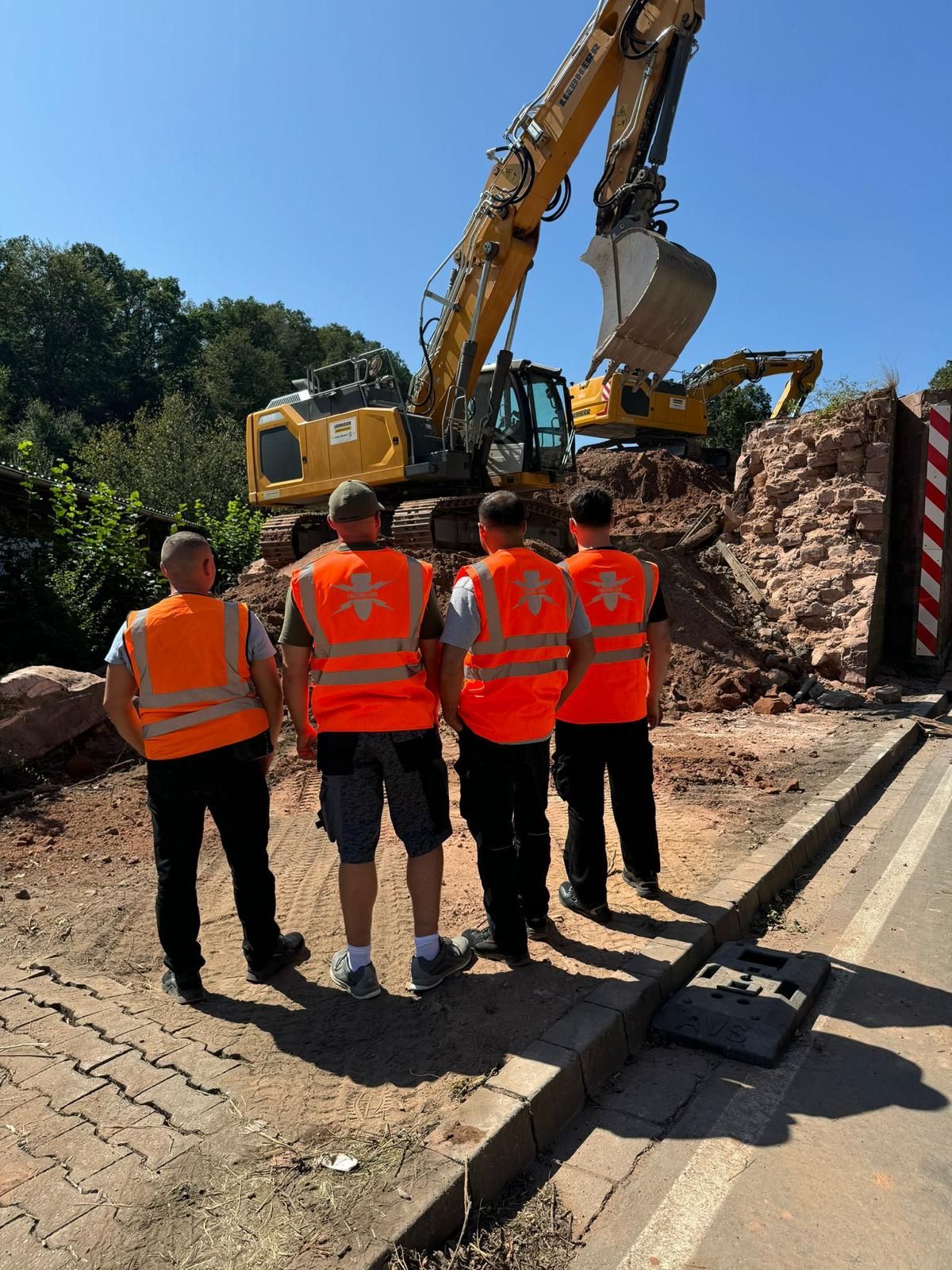
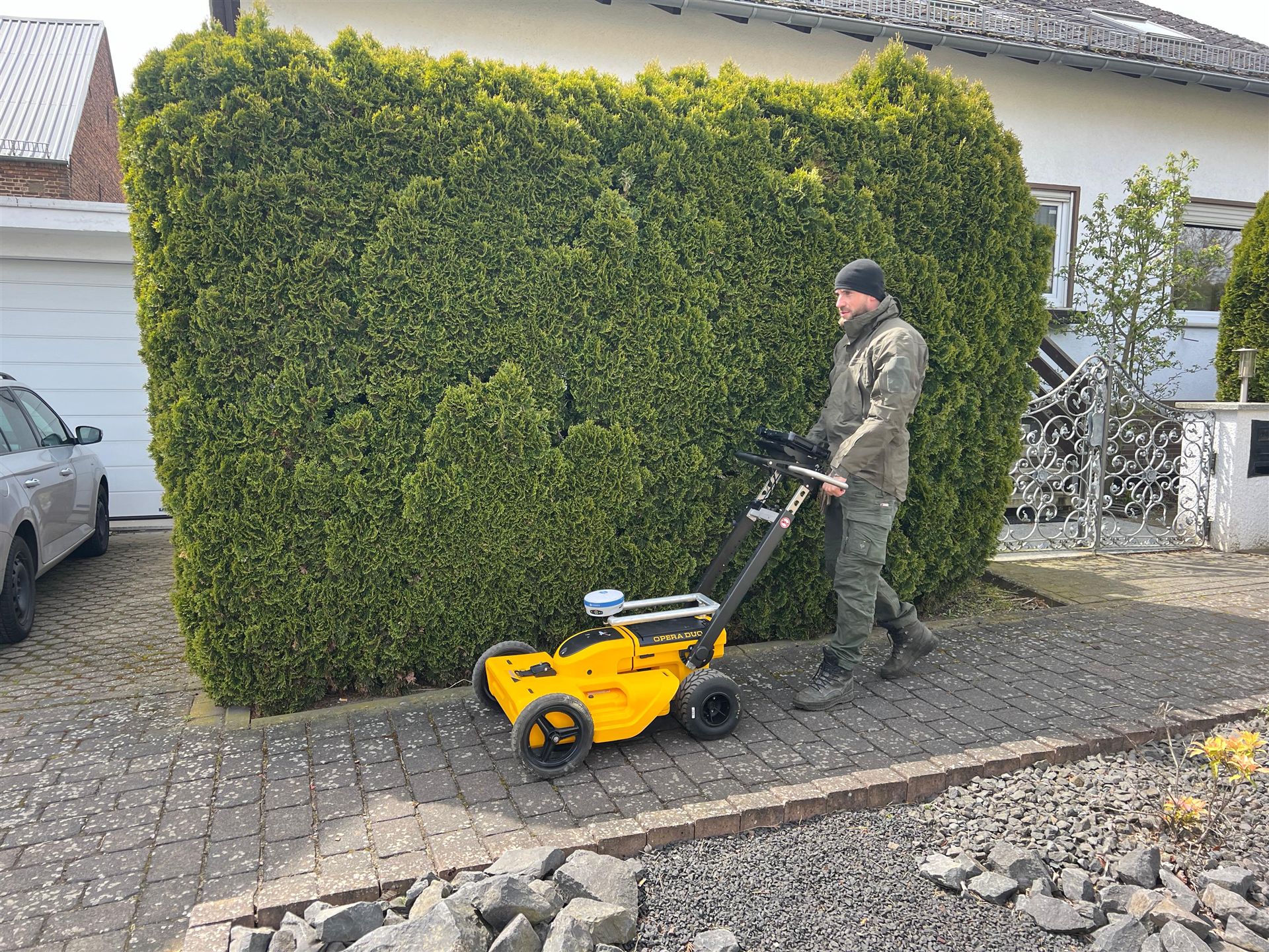
Historical suspicion assessment, surveys, deep investigation, construction-phase investigation and evidence refer to the same route sections and installation sites.
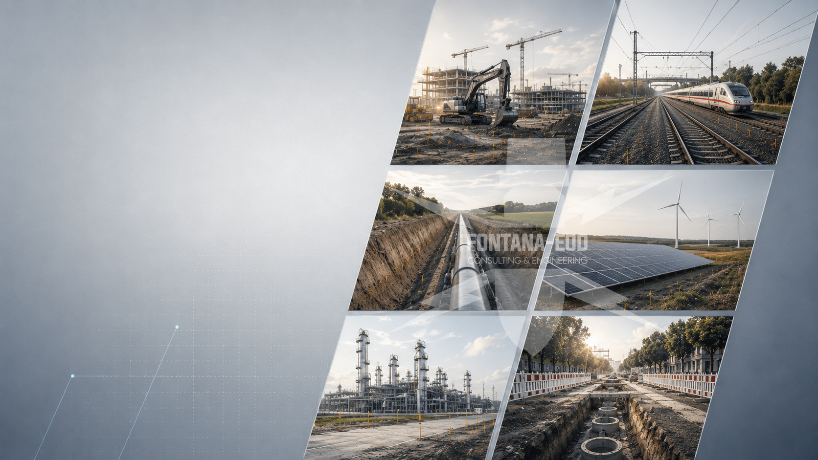
Plan ordnance assessments for transport, utility, energy and other infrastructure projects according to their ground interventions.
Assess the project environment
Distinguish utility corridors, crossings, foundations and installation areas by construction method and intervention depth.
Assess the utility project as a whole
Provide a spatial basis for suspected sections, data gaps and technical priorities in utility and energy projects.
Clarify historical suspicion indicators
Investigate deep work volumes for boreholes, chambers, pylons, crossings and foundations at their actual positions and depths.
Investigate deep work volumes
Establish the suitability and sequence of construction-phase ordnance surveying for remaining excavation areas.
Prepare the excavation sequence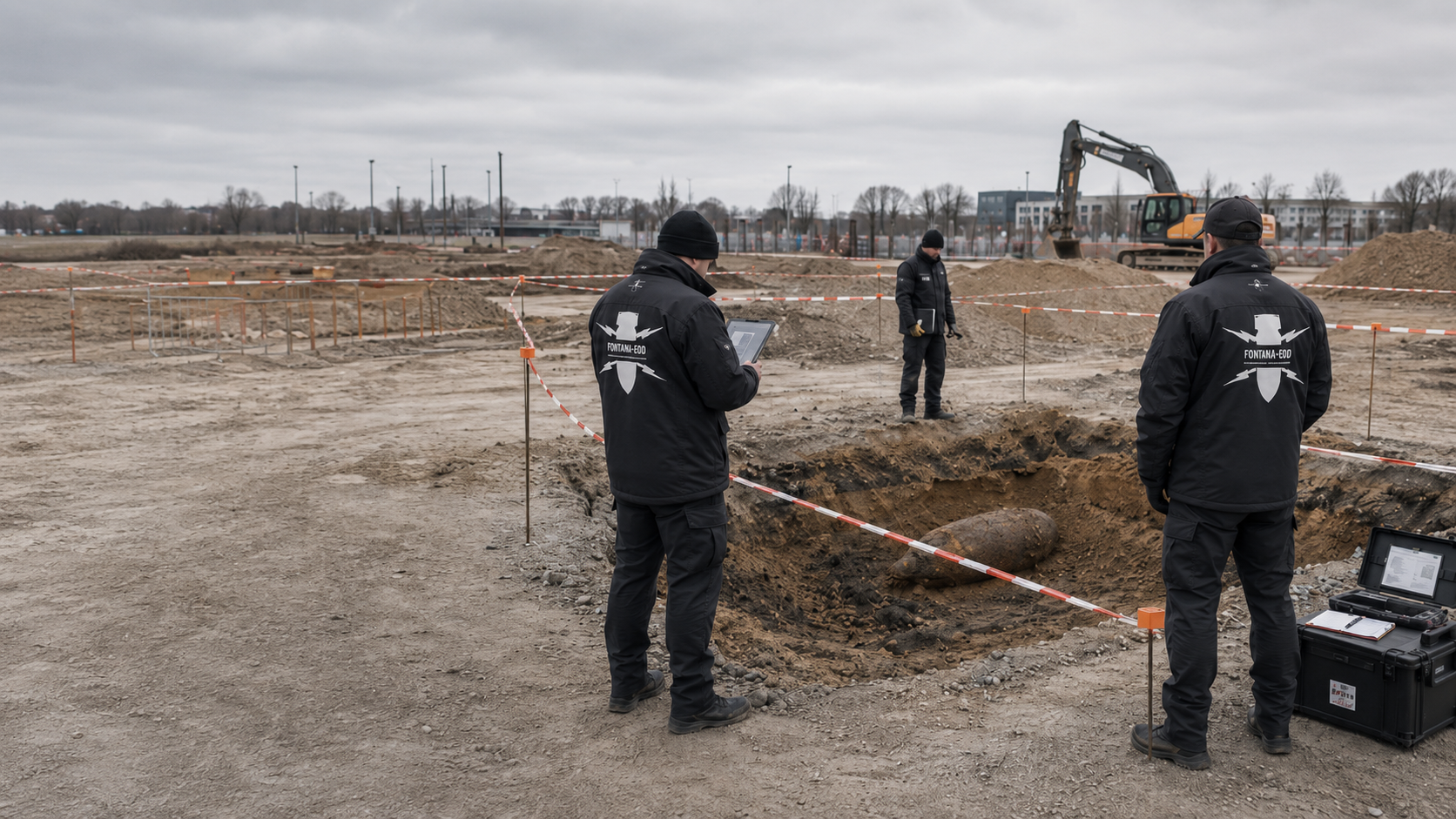
Coordinate recovery of confirmed ordnance with the permitted activities and local responsibilities.
Coordinate the processing of findings
Define service specifications, data structure, quality control and partial handovers for utility and energy projects.
Prepare tendering and documentation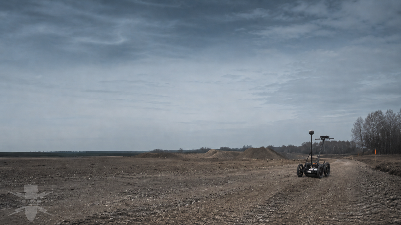
Arrange specialist review of the site plan, route, intervention geometry, plan revision and decision date for utility and energy projects.
Enquire about a utility or energy project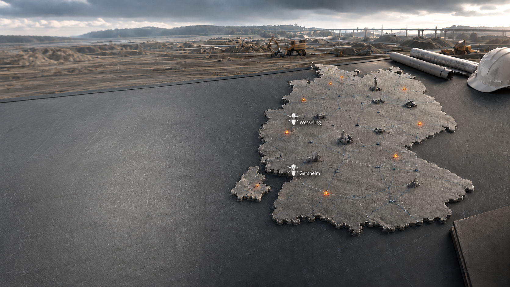
State project locations, lot boundaries, chainage and site identifiers. Existing requirements are assigned to each section. Where several municipalities or project sponsors are involved, it must remain clear which documents and contacts belong to each spatial part of the project.
Evidence for a utility corridor does not automatically describe the deeper foundations of a station. Compare position, depth and plan revision for each subproject. Shared project identifiers facilitate assignment but do not extend the investigated volume.
Check evidence against the interventionAt lot boundaries, areas dealt with, remaining gaps and responsible contacts must be brought together. Changes to the route or construction method are updated in the shared plan revision so that outstanding tasks are not lost between subprojects.
Explore the technical principlesTechnical information
Utility routes, substations and energy installations place different demands on ordnance assessment. The brochure shows the design information needed and how investigation, construction sequence and documentation fit together.
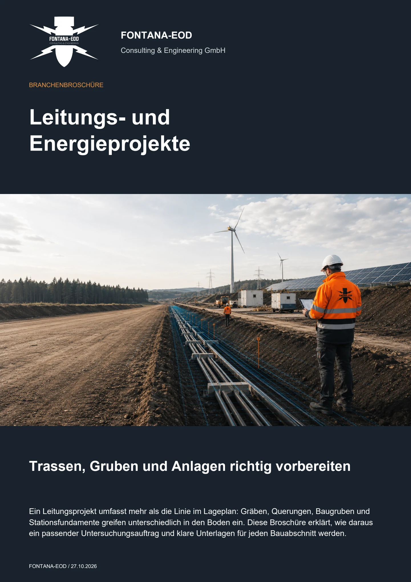
Investigation requirements are established from existing suspicion indicators and planned ground interventions. Trenches, boreholes, piles, pylons, chambers, foundations and installation areas are considered. Assessment should take place early enough to allow changes to options, approvals, the bill of quantities and construction schedules. The specific scope depends on suspected contamination, work volume, construction method and the conclusion required.
This depends on the ground interventions and measurement conditions. A route may include open areas, roads, existing utilities, structures, crossings and deep point interventions. Magnetometry, TDEM, GPR, deep-ground surveys and excavation monitoring answer different questions. The combination is planned section by section and linked to a consistent location and evidence system.
Useful documents include route and site plans, chainage, work strips, construction depths, structures, crossings, point lists, utility and existing-asset plans, historical analyses, authority documents, geotechnical data, construction phases and the required decision date. Options and areas not yet fixed should be clearly marked.
Information and requirements from authorities are supplied with their date, complete appendices and geographical scope. In Germany, the competent ordnance disposal service, local public-order authority and, where relevant, building-control authority are identified for the project location; outside Germany, local responsibilities apply.
If an unexpected suspicious object is found, stop work. Do not touch, move or uncover it further. Leave the immediate area and warn others without putting yourself at risk. In Germany, notify the police on 110; outside Germany, use the local emergency reporting procedure. The competent authorities determine what happens next; a project enquiry does not replace reporting the find.
Interference fields, operating installations, lack of access and existing structures may limit advance investigation. The zones are marked on the plan and suitable additional measures and possible access after demolition or exposure are defined. Where construction-phase ordnance surveying is technically suitable, each working layer is technically surveyed and assessed before controlled removal with supplementary visual inspection. Necessary investigations and protective measures are also planned before ground interventions during breaking out or demolition; areas not covered remain unresolved.
Routes, areas and points receive a consistent chainage, coordinate and identification system. Measurement data, borehole positions, anomalies, field records and section reports refer to the same geometry. Progress, outstanding measures and plan changes can therefore be updated across lots, contractors and construction phases.
In Germany, the ordnance disposal services of the federal states and the locally competent authorities carry out hazard-response and find-management duties. Outside Germany, local responsibilities apply. The private specialist company performs the commissioned assessment and documentation. Reporting procedures, contacts and project communication are established for each section or installation site before work begins.
Factors include route length, installation area, number of deep points and crossings, surfaces, interference environment, access, construction phases, required methods, data formats and documentation scope. A reliable calculation therefore requires current plan revisions and an unambiguous description of the work volumes actually to be dealt with.
An enquiry need not contain a complete bill of quantities yet. It should, however, identify the project type, spatial geometry, intended interventions, design stage and decision required.
A reliable initial review should also show which areas are required permanently, used only temporarily or planned for a later phase. This allows the investigation scope to be phased appropriately.
Send site and route plans with chainage, work strips, installation areas, structures, crossings and point lists.
Mark options, priority sections and geometries not yet fixed.
For long projects, the intended lot and section structure should be identifiable.
Describe open trenches, boreholes, piles, pylons, chambers, foundations, demolition and excavation with maximum depths.
State construction windows, operating conditions, access and the planned sequence.
Temporary construction roads, assembly and storage areas are also relevant where they involve ground intervention.
Attach historical analyses, information from authorities, utility plans, geotechnical data and earlier reports.
State whether the result is needed for options, approval, procurement, site management, the operator’s file or section handover.
Incomplete or contradictory documents may be included and show the clarification still required.
A site plan, brief project description, route length or installation area, maximum depths, number of crossings and deep points, planned period and existing suspicion indicators are often enough for an initial assessment. FONTANA-EOD then identifies the information still required and the appropriate service area.
For large projects, work can be phased according to design maturity, priority and construction section. This provides reliable decisions early without making blanket assumptions about later corridors or corridors still subject to change.
Required approval, operator and handover formats should also be specified. A project requiring digital route data, point-specific status lists and sectional reports needs a different data structure during field planning from a single local construction project. These requirements affect surveying, interpretation, report structure and subsequent updates.
Route, chainage, work strip, installation area, structure, point list and plan revision.
Trench, drilling path, chamber, foundation, pile, pylon, demolition and maximum depth.
Operations, traffic, access, interference sources, construction phases, parallel trades and decision dates.
Documents for design, approval, procurement, site management, the operator’s file or partial handover.
Whether historical aerial photograph analysis, explosive ordnance surveying, surface surveying using GPR, magnetometry or TDEM, deep-ground surveys, downhole surveys, excavation supervision, area clearance or ordnance recovery is needed depends on the location, ground disturbance, depth, ground and existing documents. An early ordnance assessment provides clarity for tendering, programming, occupational safety and construction.
FONTANA-EOD combines its Section 7 SprengG licence, specialists holding Section 20 SprengG certificates of competence, suitable survey and clearance methods, and traceable documentation. Send the site plan, depth of ground disturbance, construction phase and existing documents for an initial technical assessment.


