Project pathway
The quickest route to the right decision.
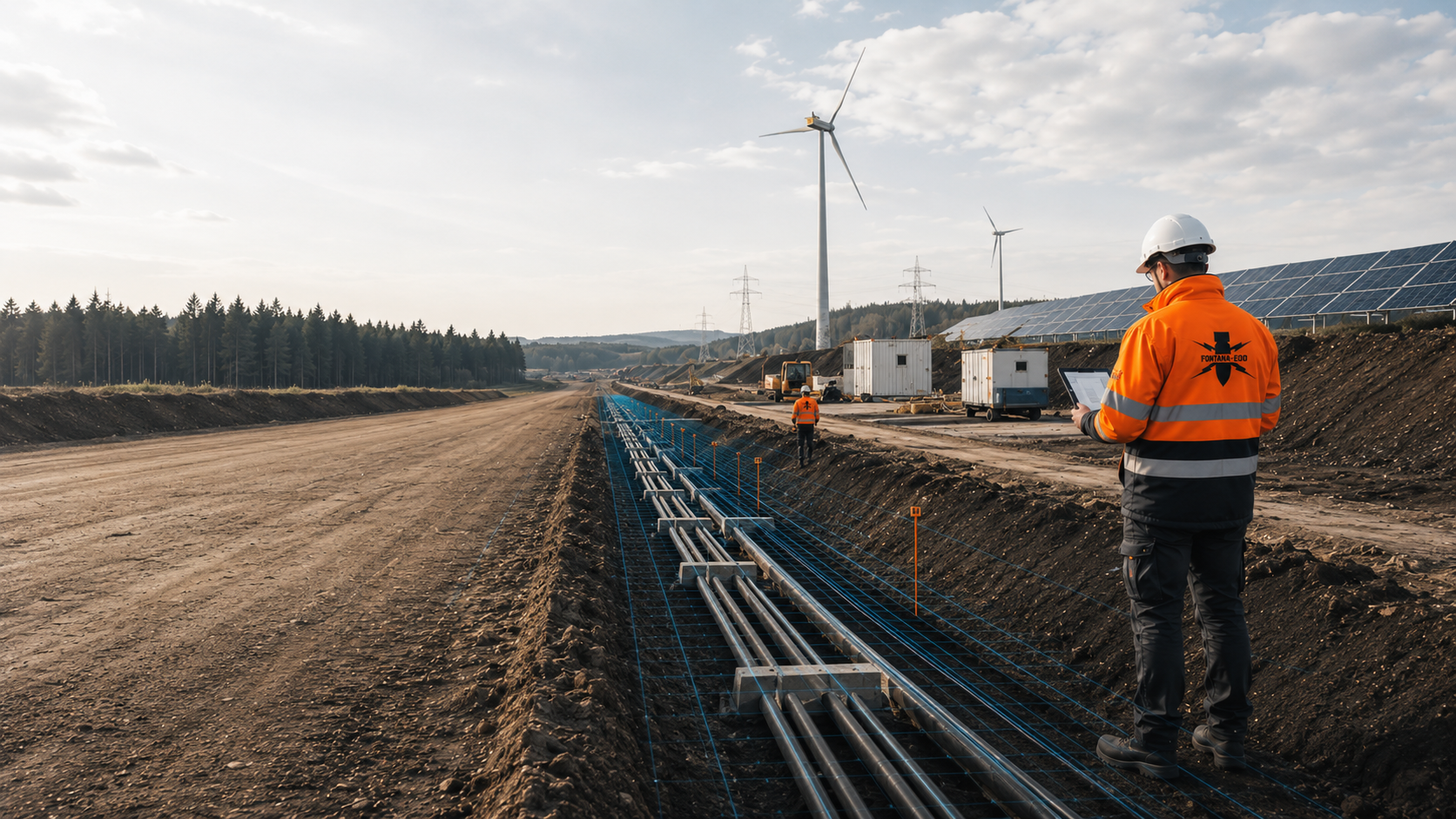
For cable route construction, we consider standard trenches, joint bay excavations and crossings with their different areas and depths. FONTANA-EOD plans suitable surveys according to chainage, working width, depth and construction phase. Send the route plan, pit dimensions, cross-sections and crossing documents so that services and documentation can be defined before the respective ground interventions.
Identify sections, crossings and pits.
Define width, depth and shoring.
Coordinate excavation, cable pulling and documentation.
Before cable trenches, joint bay pits and chambers are excavated, existing hazard indications and planned ground interventions are used to clarify which explosive ordnance surveys are required.
The linear route section and the larger individual excavations present different tasks. Joint bay excavations may be wider, deeper and associated with shoring, dewatering or additional working spaces; their assessment must therefore not be inferred from a narrow survey line along the cable alignment.
The scope of work for “DB Cologne junction – track and cable civil engineering, North Rhine-Westphalia” included explosive ordnance surveys and supervision during construction.
Service period: –
Service areas:Ordnance specialist supervision of groundworksSurface surveys: GPR, TDEM and magnetometry
Cable projects consist of recurring standard cross-sections and individual special structures. Trenches, joint bay pits, chambers, crossings and construction site areas differ in geometry, depth and technical interference.
Explosive ordnance surveys are therefore planned by chainage and asset. The surveys available and outstanding tasks are documented for each section.
For long routes, work can be divided by construction contract, priorities and work windows without abandoning a shared data and documentation structure.
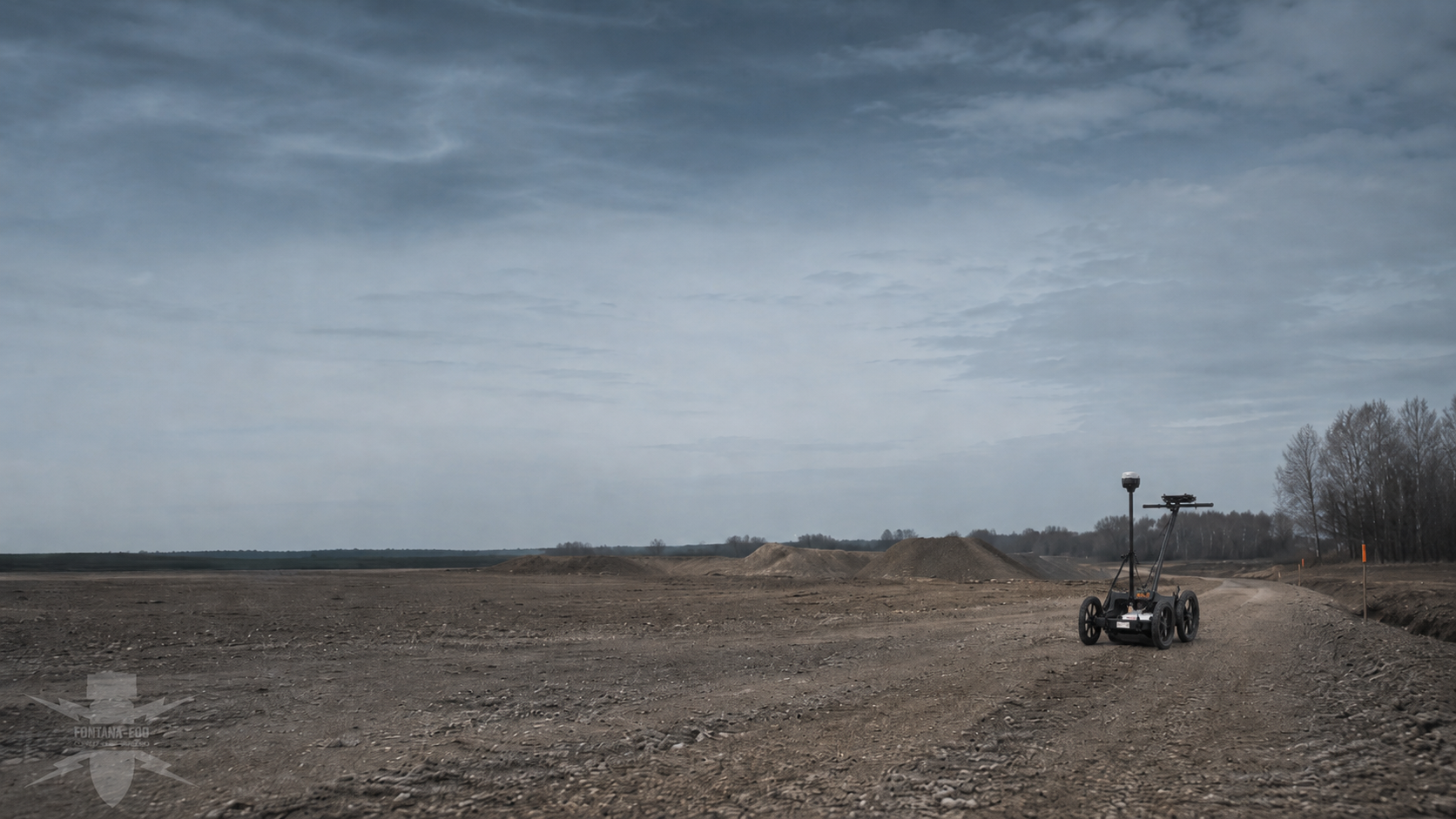
The linear trench is described with its alignment, working width, slopes or shoring, trench depth and construction section. In addition to the cable zone itself, working strips, separate soil storage and drainage may involve ground intervention.
The survey or supervision geometry follows the entire earthworks volume. Changes in chainage and bends in the route are clearly recorded in the documentation.
Assess cable trenches by section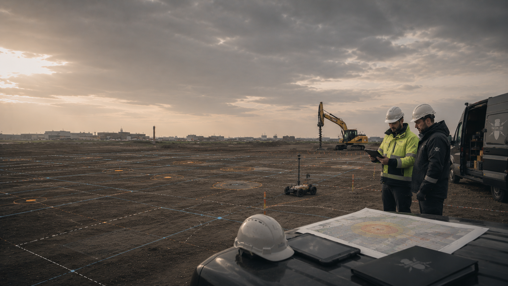
Joint bay excavations may extend beyond the standard trench. Their actual dimensions and work areas are taken from the construction design. Shoring, access ramps, pump sumps, cable pulling and assembly determine the actual volume of ground affected.
Each pit receives its own identifier, area, depth and construction phase. The status of the adjacent route is not automatically extended to the entire joint bay excavation.
Select a suitable survey for the pit geometry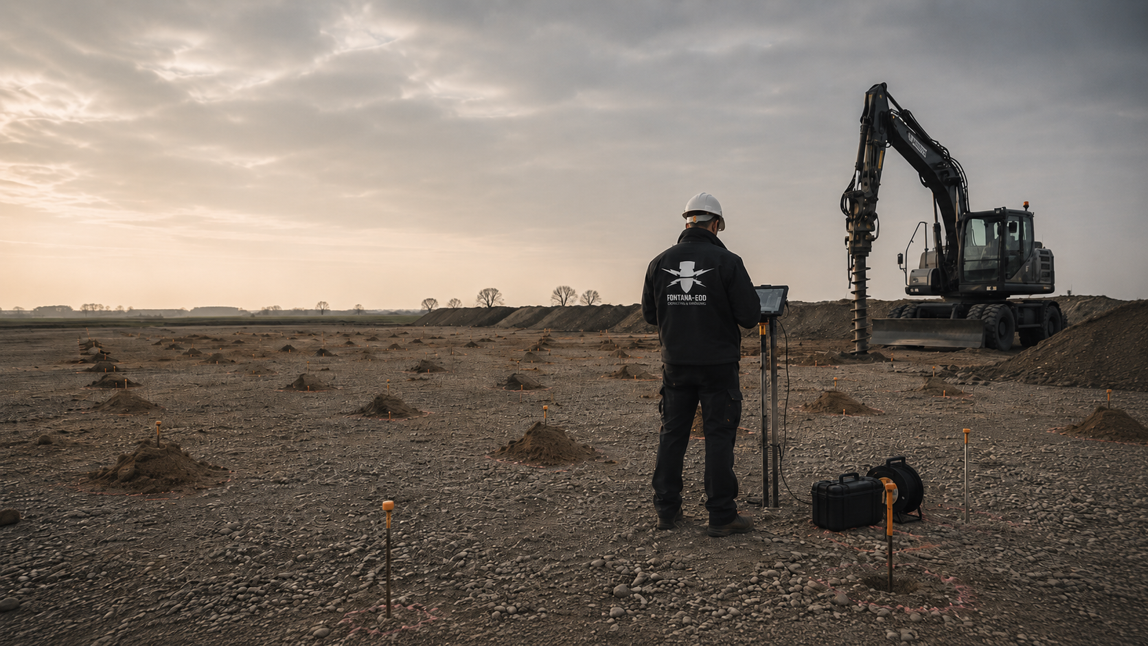
Roads, watercourses, railway lines and other infrastructure may be crossed using ducts, thrust boring or guided drilling. The launch and reception pits differ from the deeper bore path.
The explosive ordnance assessment is coordinated with the pits, borehole locations, alignment and possible positional deviations. Suitable methods and the achievable scope of assessment are considered separately for inaccessible volumes at depth.
Assess the crossing and bore path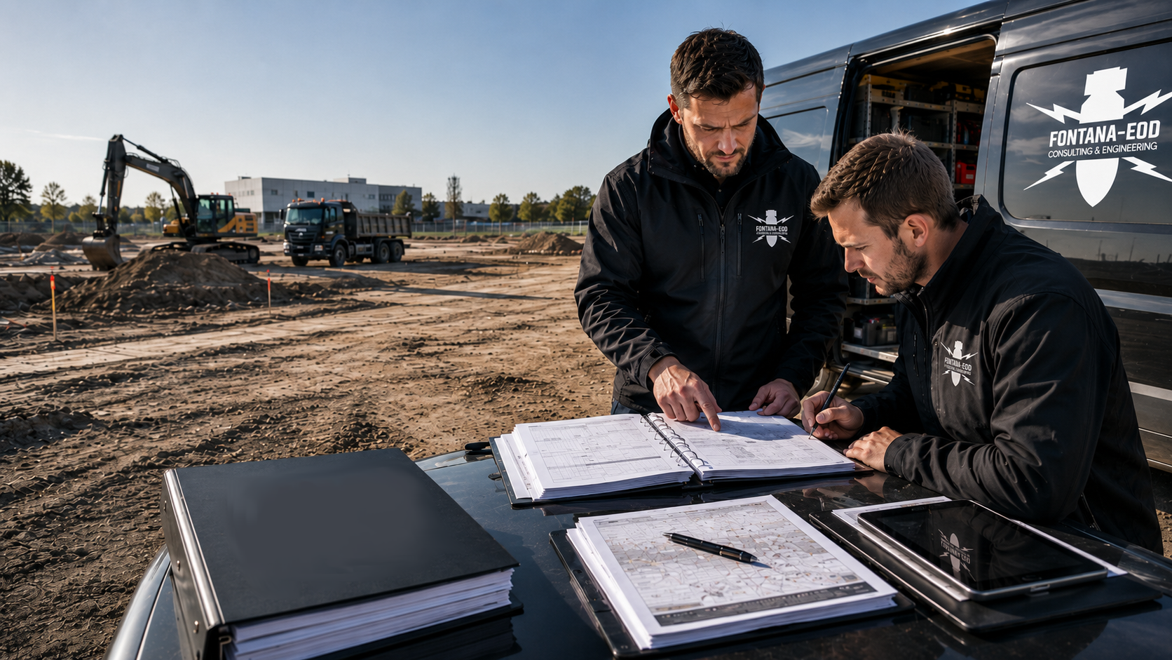
Cable chambers, transfer structures, earthing connections and technical ancillary installations create additional point and area geometries. Their depth may differ from the standard trench.
The design assigns these structures to the relevant route section and identifies areas not yet surveyed.
Document chambers and transfer pointsStreets, commercial areas and existing service corridors often contain numerous cables, pipes and metal installations. These affect survey feasibility, accessibility and safe earthworks.
Open survey zones, sections affected by technical interference and areas accessible only after exposure are assessed separately. The plan identifies the next measure for each zone.
Select supplementary methods for sections affected by interferenceHaul roads, cable drum areas, storage and assembly areas may require soil replacement, formation preparation, drainage or foundations. This creates assessment areas outside the cable trench.
Only areas involving actual ground intervention are included. The permanent route and temporary construction logistics remain distinguishable on the site plan and in the report.
Assess construction logistics and additional areasThe project question changes between route option planning, approval, tendering and construction. A reliable explosive ordnance assessment must address the current route and pit design at each stage.
We assess whether historical documents are sufficient, technical surveys are needed or supplementary surveys during construction are suitable.
At an early stage, we clarify which route options intersect historical suspected hazard areas, existing infrastructure or zones that are difficult to access.
The assessment provides a basis for comparing options and planning technical surveys without asserting the present location of objects.
Joint bay locations and special structures are considered as soon as their positions can be anticipated.
Assess the route corridor using historical evidenceWorking width, trench depth, slopes or shoring, soil storage, dewatering and construction sequence determine the actual assessment geometry.
Joint bay excavations and chambers are incorporated into the design with their own dimensions and depths.
This keeps the service scope traceable even where cross-sections change.
Assess the standard cross-section and pitsAreas, lengths, pit numbers, crossings, depths, accessibility, interference and required documentation are described for each contract or construction section.
Historical, geophysical, depth-specific and construction-phase services receive separate items.
Triggers, scope and required documentation for possible additional services are described in advance.
Structure the bill of quantities and documentationThe near-surface pits and the deep crossing volume are treated as different tasks.
Coordinates, drilling angle, target depth, diameter and positional deviations inform the assessment.
The report shows which areas were surveyed and what assessment is achievable for the bore path.
Assess the crossing geometry at depthExisting services and technical installations can restrict surveys in advance. Areas where data cannot be evaluated are spatially defined before work begins.
For remaining areas, the technical suitability of explosive ordnance surveying during construction is assessed. Each working layer is technically surveyed and evaluated before controlled removal in layers with supplementary visual inspection. These steps are repeated down to the agreed excavation base. Excavation layers, hold points, authority to issue instructions, communication channels and documentation are defined before work begins.
Design changes or additional chambers are checked against the existing status of work.
Organise excavation around existing utilitiesAn anomalous survey response is initially assessed by location, depth and technical surroundings. Utilities, scrap metal and structural remains can cause similar signals.
If further investigation is required, exposure and communication about findings are coordinated for the specific construction section.
For a suspicious object, stop work immediately, keep a safe distance and notify the police immediately on 110 in Germany; outside Germany, the local emergency reporting procedure applies.
Document findings and further measuresThe linear route, individual special structures and deep crossings must not be combined into a blanket area assessment. Survey requirements are determined for each volume of ground affected using the planned geometry and available information.
The documented status identifies areas addressed, limitations and what is still required before the next earthworks or cable installation step.
Initial situation: Several corridors are being compared; precise trench geometries and joint bay locations remain undecided.
Technical step: Historical sources and known indications are related to the options to identify sections with suspected hazards and data gaps.
Documentation objective: Planning can take account of survey requirements, construction time and possible redesign at an early stage.
Assess alternative corridors using historical evidenceInitial situation: The alignment, working width, depth and construction section are defined; the area is accessible.
Technical step: A suitable area-based method is selected according to the target object, ground conditions and interference.
Documentation objective: Survey coverage, anomalies, limitations and further measures are documented by chainage.
Technically assess the route sectionInitial situation: The planned pit extends beyond the standard trench and has additional working or shoring areas.
Technical step: Area surveys, deep intervention points and, where applicable, sections requiring work during construction are derived from the pit layout.
Documentation objective: The status applies to the complete documented pit geometry, not just the cable alignment.
Coordinate methods for the entire pit volumeInitial situation: A deep bore path connects the launch and reception pits beneath an obstacle.
Technical step: Pits, entry points, depth profile and possible positional deviations are surveyed and assessed separately.
Documentation objective: Designers and site management can identify which assessment applies to the bore path and which applies only to the pits.
Assess the bore path and pitsInitial situation: Numerous existing services and previous excavations limit area-wide geophysical evaluation.
Technical step: Areas that can be surveyed are investigated. For remaining zones, suitable supplementary surveys are assessed, including whether more information or a different construction stage is needed.
Documentation objective: Limitations and alternative measures remain spatially traceable.
Determine surveys for route areas that cannot be surveyedInitial situation: A signal or historical indication relates to the cable trench, a joint bay excavation or a chamber.
Technical step: The anomaly is assessed for plausibility against existing asset data, depth and construction geometry and prepared for further investigation.
Documentation objective: The findings status, handover and remaining work boundaries are clearly assigned to the chainage section.
Locate findings status and handover spatiallyLong cable projects need documentation that remains spatially unambiguous despite multiple construction contracts, design changes and work windows. Chainage and asset identifiers link fieldwork, construction design and project records.
A report must distinguish whether its assessment applies to the standard trench, a joint bay excavation, a crossing or only part of an area.
The route alignment, chainage, construction contract, coordinate system, land parcels and design revision form the basic spatial structure.
Crossings, joint bay excavations, chambers and changes in direction receive unique asset identifiers.
Working width, trench depth, slopes or shoring, soil storage and construction conditions are documented for each section.
Joint bay excavations, chambers and launch or reception pits are recorded with their own area and depth.
Aerial photograph assessments, authority information, earlier reports, previous route uses and existing utility plans are brought together.
Conflicting information and data gaps remain visible in the project status.
Survey lines, areas, grids, borehole locations, assessment depths, surface conditions and sources of interference are documented with georeferencing.
Raw data, evaluations and anomaly lists use the same chainage and asset identifiers.
Existing utilities, technical interference, lack of access or changed construction methods can limit the survey.
These areas are mapped. Suitable supplementary methods and possible survey dates are defined separately.
The report describes route lengths, pits and depths addressed, findings, limitations and follow-up decisions.
New joint bay locations, route realignments or additional chambers are checked against this status.
The dossier links historical evidence, technical surveys, pit and crossing status and communication during construction. It shows the information available and outstanding measures for each section.
When designs are revised or contractors change, design revisions and outstanding tasks are updated in the handover documents.
Construction contracts, chainage, joint bay excavations, chambers, crossings and work areas are maintained in a shared list.
The design revision and change history show the geometry underlying each assessment.
Suspected hazard areas and source information are shown along construction sections and special structures, rather than only as broad areas.
This allows technical assessment requirements to be prioritised specifically.
Areas, lines, borehole locations, depths and field conditions are assigned to chainage locations and pit identifiers.
The data structure supports links to civil engineering, cable pulling and construction programme planning.
Anomalies, exposures, technical sources of interference and actual finds receive a traceable work status.
Outstanding points are recorded with the planned measure and reference to the next construction section.
The client, designers, civil engineering contractors, HSE, cable installation teams and responsible authorities receive the information needed for their roles.
Handovers identify chainage, design revision, the outstanding volume of ground and the decision required.
Reports, site plans, data lists and records are brought together in route-specific project records. After actual exposure or clearance work, the corresponding findings and clearance records are included.
Changes to the alignment, pit geometry or construction method are added without extending older results indiscriminately.
The sequence links early assessment of suspected hazards with developing route and detailed design. The more precisely trenches, pits and crossings are defined, the more precisely the technical assessment can be designed.
Section handovers enable construction to progress without obscuring outstanding areas or later design changes.
Route length, network level, construction method, construction contracts, joint bay excavations, crossings and the required project decision are recorded.
Early route options and defined sections remain distinguishable in the baseline data.
Historical assessments, authority information, existing utilities, ground investigation data and existing survey reports are checked against the route plan.
Data gaps and conflicting chainage references are clarified before fieldwork planning.
Standard trenches, joint bay excavations, chambers, crossings, access roads and storage areas are described with width, depth and construction conditions.
This geometry determines quantities, methods and documentation.
The target object, surface, ground conditions, utility density, depth of usable data and accessibility determine the suitable combination.
For deep crossings and sections affected by technical interference, the need for and suitability of supplementary methods are assessed in advance.
Chainage, survey areas, pit identifiers, exclusion areas, access roads, dewatering and contacts are checked before mobilisation.
The deployment sequence follows civil engineering and cable pulling dates. Necessary surveys and protective measures are planned before ground intervention during surface opening, dismantling or creation of access.
The agreed area-based, depth-specific or construction-phase surveys are carried out within the documented volume of ground.
Departures and inaccessible sections are immediately recorded on the plan and in field records.
Readings, anomalies, exposures and known utilities are checked against suspected hazards and construction geometry.
A specific follow-up measure is identified for each outstanding point.
The report, maps, pit and anomaly lists and limitations are prepared for designers and site management.
Route realignments or new joint bay locations trigger a targeted check against the existing status.
The explosive ordnance task involves more than a line on a route plan. Standard trenches, joint bay excavations, chambers, launch and reception pits, bore paths and construction site areas have different spatial extents and depths.
The respective areas, depths and survey boundaries are stated separately within the shared chainage system.
The linear cable trench creates a continuous working corridor. Joint bay excavations and chambers expand this corridor locally, while trenchless crossings may reach deep volumes outside the open excavation.
For each volume of ground affected, the top and bottom levels, width, slopes or shoring, construction conditions and possible positional deviations are described. Crossings additionally require entry points, the bore path and expected depth development.
Existing utilities, road construction, structures and previous excavations can change survey feasibility along the route. The corridor is therefore divided into technically comparable zones and linked to different methods or work dates.
The final plan shows which route length, pit or crossing was actually addressed. Even after design changes, this makes clear which assessment remains applicable.
The standard trench is described with its alignment, base width, working width, depth, slopes or shoring and separate soil storage where applicable.
The explosive ordnance geometry follows the actual earthworks volume, not just the cable centreline.
Joint bay excavations have their own dimensions, access, shoring and assembly areas. Their volume may differ considerably from the linear trench.
The assessment is therefore planned for the specific structure and linked to the adjacent route without treating both areas as identical.
For trenchless crossings, launch and reception pits are recorded with their respective areas, depths and construction stages.
The bore path between them is considered separately because it may lie outside the near-surface pit assessment.
Cable chambers, earthing connections, transfer structures and technical nodes create local deeper interventions within the route corridor.
They are documented with their own identifier, depth and link to the relevant construction section.
Existing cables, pipes, protective systems and previous excavations can obscure survey data and constrain the excavation volume.
The report distinguishes areas where data can be evaluated from zones subject to technical limitations. Suitable supplementary surveys are assessed for remaining areas.
Route alignments, joint bay locations and crossings may change during approval or construction.
Each new geometry is overlaid with the existing status of work before results are reused.
Existing cables, pipelines, ducts, road structures and previous excavations can obscure geophysical surveys. These areas are marked on the route plan. Suitable supplementary methods or survey dates are assessed for them.
Select methods according to survey conditionsFor crossings, the launch and reception pits, bore path, target depth, diameter and positional deviations are considered separately. Assessing the pits addresses the entire deep crossing volume only if the selected geometry actually covers it.
Assess depth-related investigationPhysical survey methods and work during construction fulfil different tasks. A method is used only where its scope of assessment matches the specific trench, pit or crossing.
Combinations are useful where they cover separate volumes and are brought together in shared documentation.
Substantiates possible sections with suspected hazards along the cable corridor and supports prioritisation of technical surveys.
It does not show utilities or explosive ordnance currently present underground.
Can detect ferromagnetic anomalies in open route areas.
Existing cables, fences, vehicles and scrap metal can limit data evaluation in densely occupied corridors.
Detects electromagnetic responses from conductive objects and can supplement an area-based survey where ground and interference conditions are suitable.
The target object, existing utilities and desired depth of usable data are assessed before deployment.
Can show structural and material changes, utilities or distinct reflection zones on suitable surfaces.
Radar reflections alone do not provide unequivocal explosive ordnance identification and must be assessed for technical plausibility.
Assesses defined point locations and volumes at depth at crossings, chambers or deep excavations.
Borehole location, survey length and subsequent construction geometry are coordinated.
Where explosive ordnance detection during construction is technically suitable, each working layer is surveyed and evaluated using technical methods. Controlled removal in layers and supplementary visual inspection then follow; these steps are repeated down to the agreed excavation base.
Working layers, hold points, authority to issue instructions, communication channels, documentation and the trench or pit volume are defined in the work instructions before work begins.
The survey plan states the current route design and excavation dimensions. The evaluation describes the areas covered and technical limitations.
Even along long routes, different soils, existing utilities and changing construction methods remain identifiable by section.
FONTANA-EOD starts by asking which volume of ground is needed before the next construction or cable pulling step. The standard trench, joint bay excavation, chamber and crossing are treated as separate geometries.
Method selection considers historical indications, target object, surface, ground conditions, utility density and expected depth. Zones affected by technical interference are not obscured by general statements.
Survey data, chainage and the design revision remain linked during construction. Changes to the alignment, working width or pit location are checked against existing documentation before ground intervention.
Anomalies receive a unique chainage or asset identifier. This allows site management and project management to identify the affected section and necessary follow-up measure.
The final documents describe the sections, pits and depths addressed and their limitations. This keeps the documentation usable for procurement, site management, HSE and later maintenance.
The construction contract, section, pit, crossing and design revision are clearly identified before work begins.
Methods follow the working width, depth, ground conditions, interference and subsequent construction sequence.
Shoring, dewatering, soil storage, access and cable pulling are incorporated into deployment planning.
Survey lines, borehole locations, anomalies and zones that cannot be assessed remain spatially traceable.
New route locations, pits or chambers are checked against the existing status of work.
The documents identify outstanding tasks and decisions needed before the next construction section.
Using this information, FONTANA-EOD describes the areas and depths to be surveyed. For tendering and fieldwork, the missing documents and results required for each section are recorded.
Construction planning also depends on when a joint bay pit is fully excavated, when cable pulling begins and which areas remain accessible during assembly and testing. Survey dates are therefore coordinated with excavation, shoring, dewatering, cable pulling and backfilling.
Cable projects bring together grid operators, designers, civil engineering contractors, cable installation teams, HSE, specialist contractors and responsible authorities. Before construction, it is defined who reports design changes, tracks outstanding sections and receives results.
Technical assessment, authorisation for site work and authority decisions on finds are recorded as separate processes.
Define the route corridor, construction contracts, cable system, construction phases, programme objectives and documentation required.
They provide existing design, asset and hazard records and decide on commissioning further specialist services.
Translate the project into chainage, standard cross-sections, joint bay excavations, chambers, crossings and construction stages.
Design changes are documented so that their effects on areas already surveyed can be assessed.
Coordinate access, exclusion zones, dewatering, soil management, construction windows and reporting procedures.
Their requirements link explosive ordnance work with the other HSE and construction site processes.
Construct trenches, pits, shoring, crossings and chambers within the agreed geometry.
Changes to location, depth or construction method are reported to designers and the specialist contractor before construction.
Assesses suspected hazards and documents, develops the commissioned approach and documents results and limitations.
The service relates to chainage, pit identifiers, construction phase and the required project decision.
In Germany, the ordnance disposal services of the federal states and the locally competent authorities carry out hazard-response and find-management duties. Their involvement is established for the project location; outside Germany, local responsibilities apply.
The local public order authority and, where applicable, building control are involved according to their project responsibilities. Conditions and contacts are assigned to the actual route sections, joint bay excavations and crossings; reporting procedures are defined before work begins.
If an unexpected suspicious object is found, notify the police immediately on 110 in Germany; outside Germany, the local emergency reporting procedure applies. The competent authorities determine the next steps.
Construction method, project location, route surroundings and the specific activity determine organisational requirements. Qualifications, risk assessment and documentation relate to the trench, pit and crossing.
Requirements from grid operations, civil engineering, dewatering or traffic management supplement explosive ordnance planning but do not replace a technical description of work boundaries.
In Germany, § 7 SprengG concerns the commercial authorisation for activities requiring authorisation; § 20 SprengG concerns the certificate of competence of responsible persons. Under § 1b SprengG, searching for found munitions also counts as handling them. The requirements applicable to the project depend on the activity actually commissioned and the allocation of responsibilities.
The risk assessment considers trench and pit excavation, shoring, dewatering, construction machinery, existing utilities, crossings, exclusion zones, escape routes and communication.
DGUV Information 201-027 supports risk assessment and protective measures for explosive ordnance clearance work. The Baufachliche Richtlinien Kampfmittelräumung contain requirements for historical and technical investigation, clearance concepts, procurement and documentation within their defined federal remit. Their application to the specific cable project is clarified separately.
A planned route survey must be distinguished from an actual find. If an unexpected suspicious object is encountered, stop work in the affected area immediately. Do not touch, move or continue to expose the object. Leave the danger area and keep others away without putting yourself at risk. In Germany, notify the police immediately on 110; outside Germany, use the local emergency reporting procedure. The responsible authorities determine the next steps. Then inform site management and the grid operator.
Acceptance of a section, authorisation for civil engineering in a volume of ground and authority decisions on finds are not conflated. At each handover point, the required document and decision are defined.
The First Ordinance to the Explosives Act (1. SprengV) includes requirements concerning specialist competence and state-recognised training courses. For cable routes and joint bay excavations, the required qualification is determined by the activities and volumes of ground actually commissioned.
DGUV Rule 113-003 concerns the dismantling or destruction of explosives or corresponding objects and also includes the disposal of found munitions. It applies according to this field of activity; it does not replace a risk assessment specific to the planned ground intervention.
Permits, certificates of competence, appointments and scope of responsibility must match the service actually carried out.
Trenches, pits, shoring, dewatering, existing utilities, equipment and reporting procedures are considered together.
Length, width, depth, special structures, methods, quality checks and documentation are clearly defined.
Site management, HSE, the grid operator and responsible authorities receive a procedure agreed in advance.
Route quantities, pits, crossings, depths, access, qualifications and data formats are described comparably.
Optional services receive a clear trigger and documentation scope.
The design revision, chainage, work area, existing utilities, equipment, briefings and contacts are checked.
Changes to the trench or pit are incorporated into the task.
Stop work immediately, do not touch, move or further expose the object, leave the immediate area and keep others away without putting yourself at risk. In Germany, notify the police immediately on 110; outside Germany, the local emergency reporting procedure applies.
Then inform site management and the grid operator. Work resumes in accordance with the instructions of the responsible authorities.
The deliverables link the corridor, excavations, crossings, fieldwork and construction progress. Clear assignment to chainage, asset identifiers and the design revision is decisive.
The plan links the cable alignment, standard trench, joint bay excavations, chambers and crossings to their respective work status.
Assess cable sections within the energy project
Historical sources support prioritisation of technical surveys for trenches, pits and special structures.
Examine the historical section assessment in more detail
Deep bore paths and individual deeper interventions are not assumed to be covered by near-surface route surveys. The volume at depth actually surveyed is decisive.
Survey crossings and pits at the relevant depths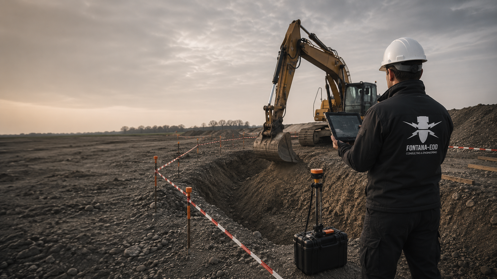
Where explosive ordnance detection during construction is suitable, investigated excavation layers and unresolved areas are documented.
Supervise trench and pit excavation
The documentation links the survey point, construction section and technical follow-up decision.
Document findings and handovers traceably
Designers and site management can trace the status of each section and special structure.
Document route-specific project records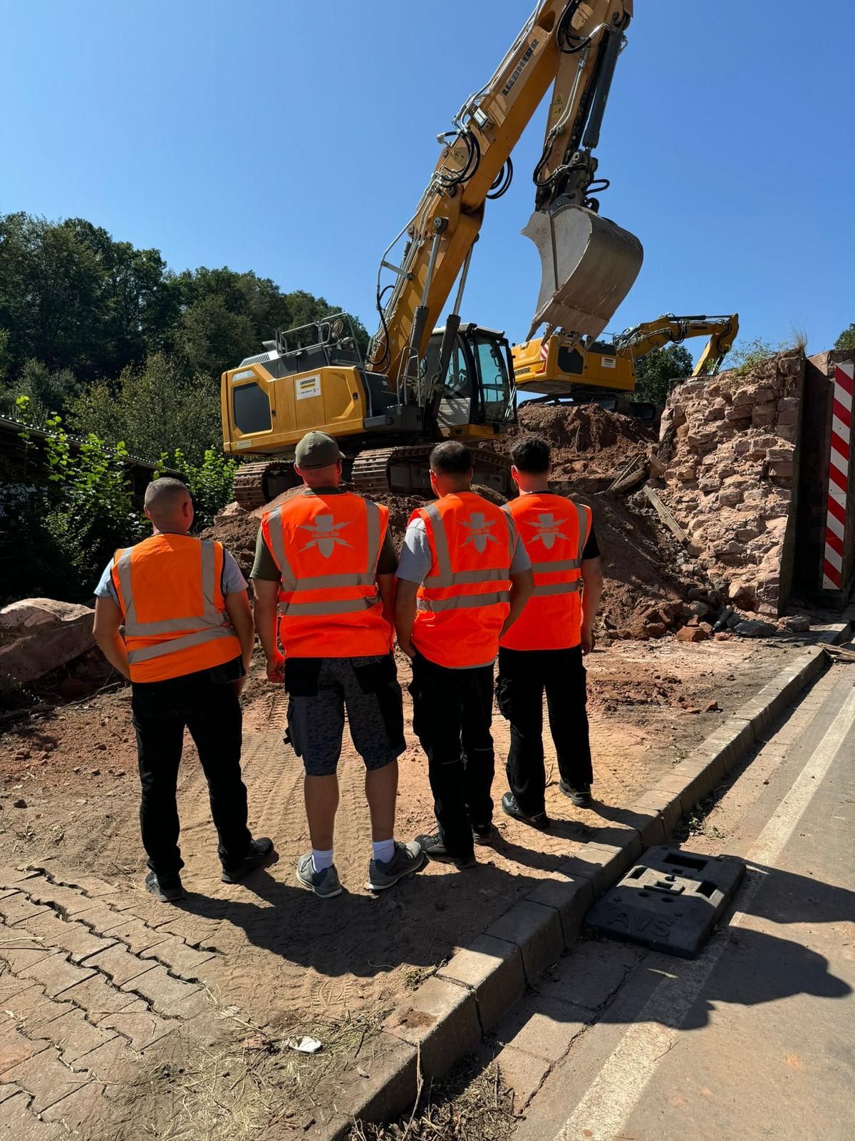
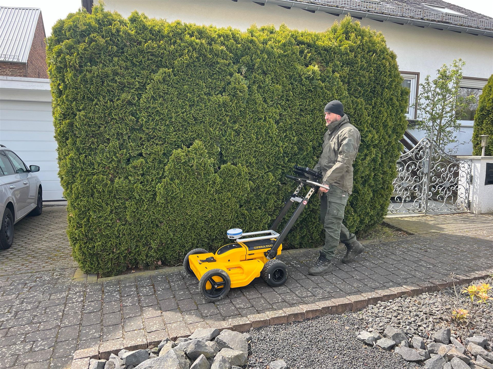
Depending on the section, cable routes and joint bay excavations require historical hazard assessment, area-based surveys, depth-specific assessment, controlled excavation or investigation of findings. Historical, technical and construction-phase services are clearly assigned to the respective volume of ground affected.
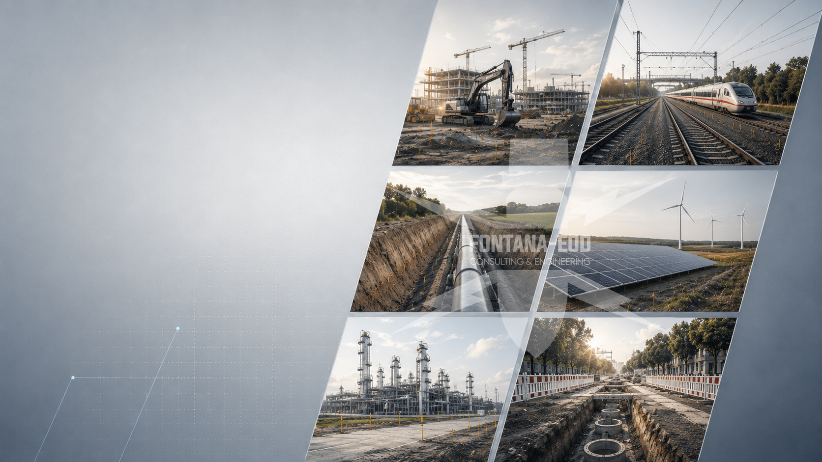
Plan ordnance assessments for transport, utility, energy and other infrastructure projects according to their ground interventions.
Compare other project types
Distinguish utility corridors, crossings, foundations and installation areas by construction method and intervention depth.
View other pipeline projects
Clarify the basis for suspicion and affected route sections before technical surveys.
Determine the historical suspected hazard
Prepare deep crossing volumes, borehole locations and special structures with their own assessment geometry.
Have deep crossings assessed
Establish the suitability and sequence of construction-phase ordnance surveying for remaining excavation areas.
Plan excavation supervision for cable construction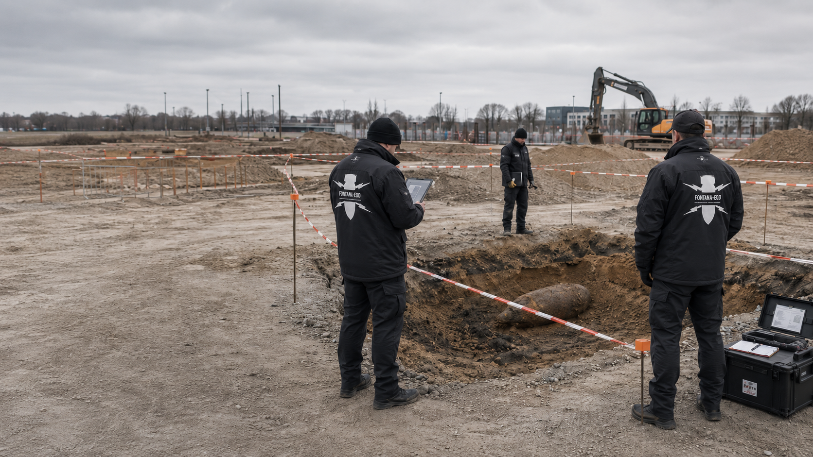
Coordinate recovery of confirmed ordnance with the permitted activities and local responsibilities.
Clarify the findings and recovery process
Coordinate the specification, chainage, pit lists, quality checks and final documents.
Prepare procurement and route documentation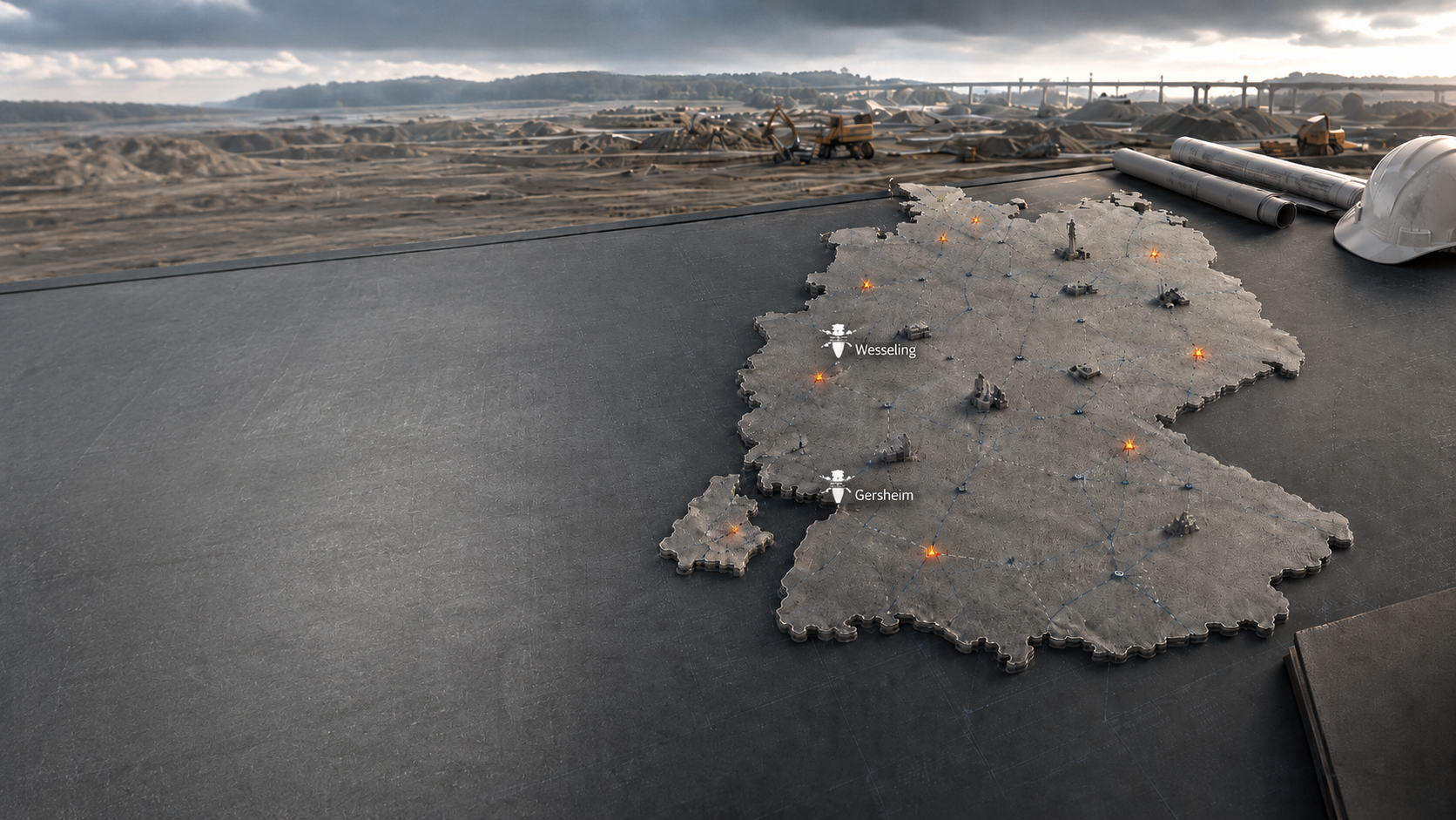
Clarify the project location and local responsibilities for planning, conditions and communication about finds.
Clarify regional responsibilitiesThe project location, chainage and pit identifiers link the route plan and survey report. Provide the location and dimensions of joint bay excavations, including working spaces. Existing requirements are assigned to each contract and construction section.
An enlarged or relocated joint bay excavation may extend beyond the area previously surveyed. Compare location, depth, shoring and working space with the documented result before the changed excavation begins.
Check evidence against the interventionBesides the route alignment, cable pulling, turning points or additional assembly areas may require their own ground interventions. Keep these areas visible on the current plan and clarify survey requirements where they are not already covered.
Explore the technical principlesTechnical information
Utility routes, substations and energy installations place different demands on ordnance assessment. The brochure shows the design information needed and how investigation, construction sequence and documentation fit together.

Route chainage, pit geometry, crossing depth, existing utilities and the required documentation remain decisive for the specific methodology.
The assessment should begin as soon as the route corridor, construction method, likely trench depth and joint bay locations are known. Before ground investigation, trial excavations, shoring, dewatering, cable trenching or joint bay excavation, it must be clear which areas require further historical and technical assessment.
Joint bay excavations may differ from the linear cable trench in width and depth and need additional working, shoring or dewatering areas. They therefore have their own area and depth geometry, which cannot be inferred solely from assessment of the route alignment.
Only if the working width, depth, crossings, chambers, joint bay excavations, site access roads and other ground interventions are fully contained within the documented survey geometry. Different or subsequently added construction areas are checked against the existing status of work before construction.
The launch and reception pits, bore path, planned depth, diameter and possible positional deviations are considered separately. Near-surface surveys at the pits do not automatically assess the deep bore path. Depending on the task, point-specific or depth-specific supplementary work may be required.
Existing utilities, ducts, cables, metal installations and previous excavations affect both survey feasibility and the volume of ground affected by subsequent work. Utility plans and a site inspection provide information for method selection. Suitable supplementary methods are assessed for zones that cannot be surveyed adequately.
Helpful documents include a route plan with chainage, standard cross-section, trench depth and working width, joint bay and chamber plans, crossing documents, bore profiles, existing utilities, construction phases, dewatering and logistics plans, historical assessments and authority information. Information and conditions from authorities are included with their date, complete attachments and spatial scope.
Decisive factors are route length, survey and working width, number and size of joint bay excavations, trench and crossing depths, accessibility, surface and ground conditions, utility density, required methods, setting out, construction windows and the scope of data and final documentation.
If an unexpected suspicious object is encountered, stop work in the affected area immediately. Do not touch, move or continue to expose the object. Leave the danger area and keep others away without putting yourself at risk. In Germany, notify the police immediately on 110; outside Germany, use the local emergency reporting procedure. The responsible authorities determine the next steps. Then inform site management and the grid operator.
An initial enquiry can be made during approval or outline design. It should identify the corridor, proposed construction method, depth and sections requiring the next decisions.
Incomplete documents also help identify the planning and clarification still required.
Send the route alignment, chainage, construction contracts, coordinate system, land parcels and current design revision.
Mark joint bay excavations, chambers, crossings, changes in direction and special structures.
For route options, it should be clear which location is relevant to the current assessment.
Include the standard cross-section, trench depth, working width, slopes or shoring, pit dimensions and planned construction sequence.
For trenchless crossings, the launch and reception pits, bore path, target depth, diameter and drilling method are required.
Temporary construction dewatering and soil replacement should be identifiable as volumes of ground affected.
Include utility, road and existing asset plans, historical assessments, authority correspondence, ground investigation data and previous survey reports.
State access, traffic or closure windows, HSE requirements and concurrent trades.
Describe whether the result is needed for planning, procurement, site management, cable pulling or project records.
For an initial assessment, a route plan, chainage, standard cross-section, joint bay locations, maximum depths, crossing details and existing hazard information are often sufficient.
FONTANA-EOD checks your documents to identify the surveys required for each section and any missing information.
Lengths, areas, pit quantities, depths, access, data formats and required documentation are defined more precisely for reliable costing.
For large cable projects, it should also be stated which data must be handed over to approval designers, construction supervision, cable installation teams and the operator. The coordinate system, file formats, chainage references and desired report structure influence fieldwork and evaluation planning as much as route length itself.
Additional priorities, such as advanced construction sections or critical crossings, should be identified with the desired decision deadline. This allows technical assessment to focus on the areas actually critical to the construction programme while remaining part of the overall route documentation.
Construction contract, chainage, coordinate system, alignment and design revision.
Joint bay excavations, chambers, launch and reception pits, crossings and shoring.
Trench depth, utility density, dewatering, access and construction windows.
Documents for planning, procurement, site management, cable pulling or project records.
Whether historical aerial photograph analysis, explosive ordnance surveying, surface surveying using GPR, magnetometry or TDEM, deep-ground surveys, downhole surveys, excavation supervision, area clearance or ordnance recovery is needed depends on the location, ground disturbance, depth, ground and existing documents. An early ordnance assessment provides clarity for tendering, programming, occupational safety and construction.
FONTANA-EOD combines its Section 7 SprengG licence, specialists holding Section 20 SprengG certificates of competence, suitable survey and clearance methods, and traceable documentation. Send the site plan, depth of ground disturbance, construction phase and existing documents for an initial technical assessment.


