Project pathway
The quickest route to the right decision.
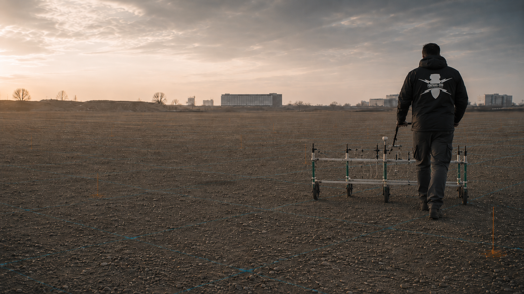
Before earthworks, clients and designers must clarify whether the ferromagnetic objects sought can be detected on their site. Magnetometry records local changes in the Earth’s magnetic field and locates anomalous signals. Send the site plan, intervention depth, documents on the suspected hazard and utility plans so that FONTANA-EOD can prepare the survey and anomaly assessment for the actual space affected by the works.
Compare the ferromagnetic target with iron sources.
Define the sensors and spatial reference.
Prioritise signals through specialist assessment.
Magnetometry is an option where ferromagnetic targets are expected and their signals can be assessed spatially under the local interference conditions. Magnetometers record local changes in the Earth’s magnetic field caused by ferromagnetic objects, iron-containing installations or magnetised materials. Dense, accurately positioned measurements produce an anomaly map that shows spatial features for further assessment.
If detectability or data quality is insufficient for the planned intervention, unresolved areas are identified and suitable additional investigations or follow-up work are defined.
The reference documents magnetic surface surveys for several railway sections in the Duisburg/Düsseldorf area. The individual sections and quantities are listed separately. View project details.
Service areas:Surface surveys: GPR, TDEM and magnetometryMethod used in this project: Magnetometry
On line 2650, track 3, km 48.530–47.470 in the Duisburg/Düsseldorf area, 4,082 m² of magnetic explosive ordnance survey is documented. View project details.
Service areas:Surface surveys: GPR, TDEM and magnetometryMethod used in this project: Magnetometry
On line 2650, track 3, km 51.048–48.533 in the Duisburg/Düsseldorf area, 10,899 m² of magnetic explosive ordnance survey is documented. View project details.
Service areas:Surface surveys: GPR, TDEM and magnetometryMethod used in this project: Magnetometry
For an open construction site, the construction boundaries, intervention depths and existing basis for suspicion are considered together. Technical preparation clarifies what conclusion is needed for the planned groundworks. Different construction sections remain identifiable on the plan so that the agreed survey scope can later be related to the actual works.
Clarify method suitability for the site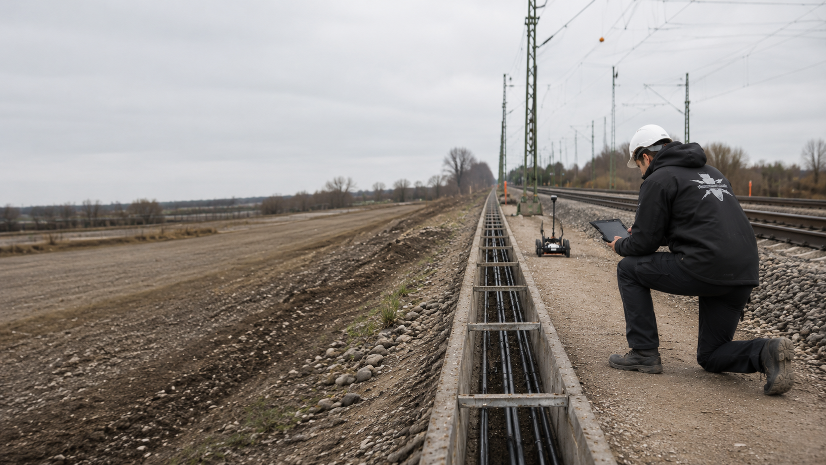
Tracks, reinforcement, fences and nearby steel structures are described as local conditions during preparation. Provide available as-built plans. Specialist planning assesses which areas can be surveyed under these conditions and where an additional task is necessary. A common area designation does not replace this local distinction.
Assess railway and route conditions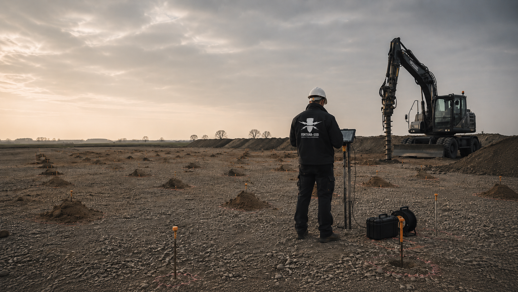
For narrow routes or individual foundations, location, depth and the space affected by the works are specified precisely. A previously surveyed neighbouring area may contain useful information, but it does not automatically cover the new intervention. Existing reports are therefore compared with current plans and their spatial limits.
Consider local interventions separately
A relocated route or deeper foundation is checked against the previous survey scope before the relevant groundworks. Earlier documentation is retained. The new technical assessment assigns usable findings and outstanding tasks clearly, rather than retrospectively extending a completed report to the entire site.
Assign changes in the project fileMagnetometry, TDEM and ground-penetrating radar respond to different ground properties. They are therefore selected according to the objects sought, local survey conditions and intervention depth.
For subsequent area clearance, the clearance objective, work limits, depth and protective measures are defined after the findings have been clarified. Accessibility, interfering bodies and the spatial distribution of targets determine execution. Findings and clearance records are linked to the anomaly list; unresolved target points and untreated zones remain identifiable.
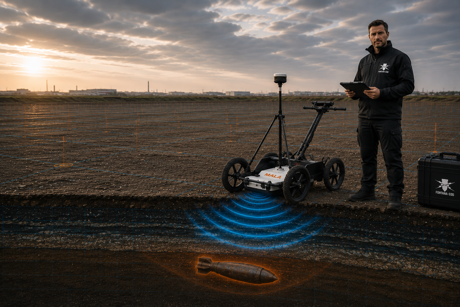
Magnetometers measure components or the total intensity of the Earth’s magnetic field. Surface surveys often record gradients or several sensors simultaneously so that local anomalies can be mapped densely and accurately in position.
Detectability depends on iron content, mass, shape, orientation, magnetisation, depth, sensor height and the interference environment. Even a large body can appear weaker than expected if its position is unfavourable or its resultant magnetisation is low.
Magnetic data, sensor arrangement, acquisition height and spatial reference are linked to the anomaly map. Interference zones and survey gaps remain distinct from interpretable areas. The target list identifies the assessment basis and next investigation without inferring an object type from the signal alone.
Compare survey methods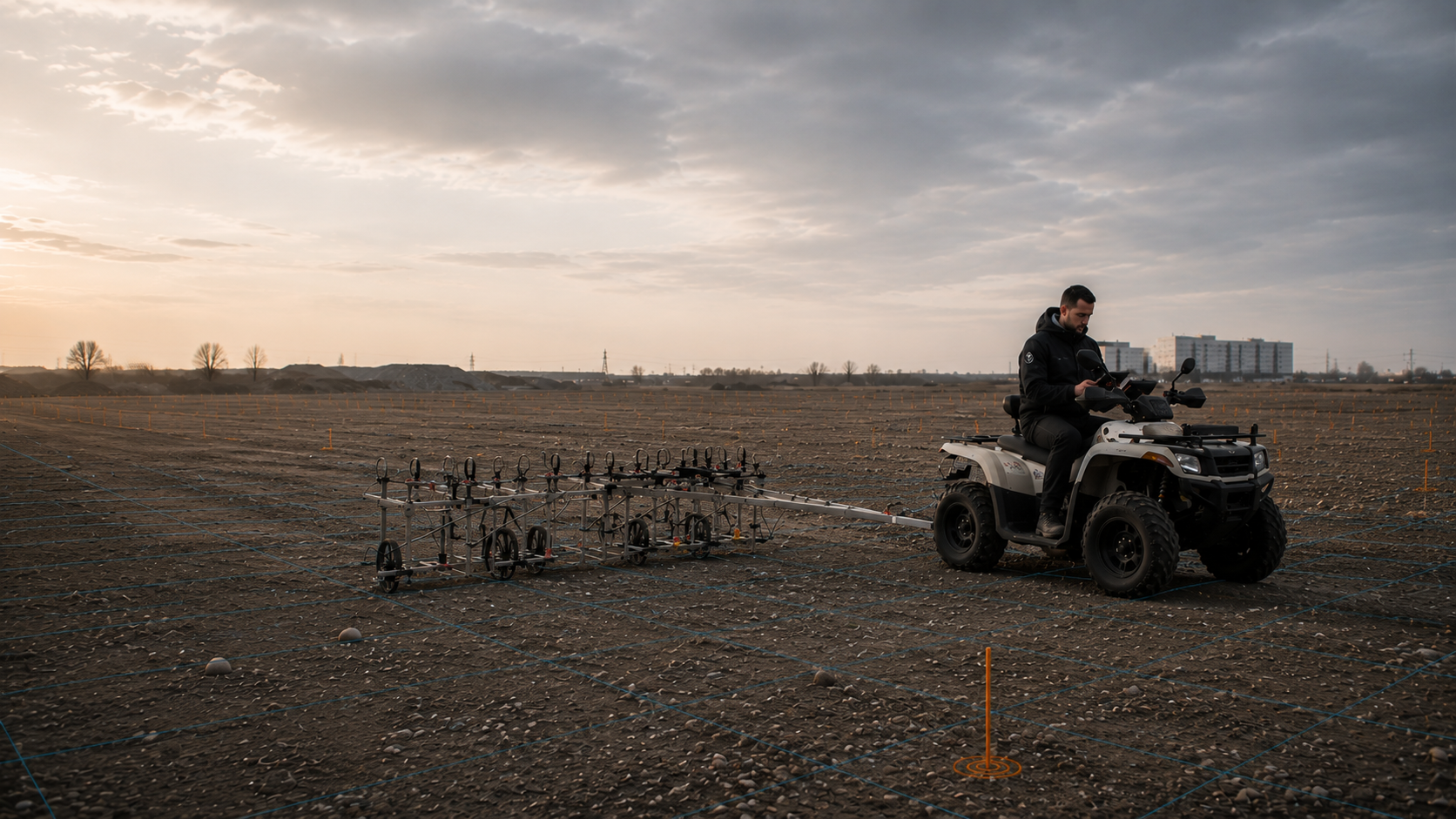
TDEM actively generates an electromagnetic field and measures the time-dependent response of conductive bodies. The method can also detect non-ferrous metals and supplement a magnetic survey where conductivity or decay behaviour provides additional information.
Services, reinforcement, extensive metal structures, survey height and ground conductivity also influence TDEM. An electromagnetic addition is only useful if it addresses a clearly defined uncertainty in the magnetic assessment.
Coil configuration, survey height, acquisition parameters and positioning data are assigned to the electromagnetic responses. When compared with magnetometry, the two survey principles remain identifiable. The report shows what additional indication TDEM provides and which anomalies remain unresolved.
Understand the scope of TDEM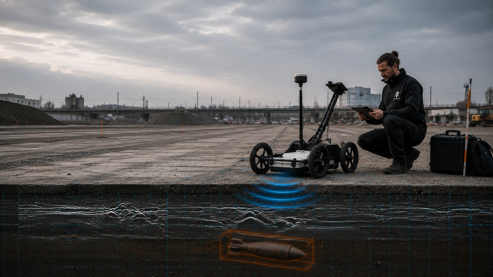
Ground-penetrating radar records reflections at changes in the electromagnetic properties of materials. Under suitable conditions, layer boundaries, made ground, service zones, foundations, voids and spatial structures can be represented.
Magnetometry and ground-penetrating radar answer different questions. A magnetic anomaly may exist without a conspicuous radar structure; conversely, non-metallic structural remains or moisture changes may produce strong radar reflections without being magnetically relevant.
Radar profiles, profile direction, spatial reference and usable depth range are documented with the assessed structures. High ground conductivity and metal installations can limit the conclusions. The combined site plan makes clear which information comes from radar and which from magnetometry.
Define the technical role of ground-penetrating radar
Historical investigation establishes the basis for suspicion, delimits subareas and describes possible links to objects or events. This provides a traceable definition of survey areas, priorities, target objects and intervention depths for the technical investigation.
This basis matters for magnetometry because a dense anomaly plan alone does not show which signals may be related to ordnance. The nature of the suspected hazard, planned use and spatial assignment guide later prioritisation.
The historical report identifies the image and archive sources used, capture dates, suspected areas and source gaps. This makes it possible to understand which expected object types and subareas underpin the magnetic survey plan. Historical observations remain distinct from current survey findings.
Prepare the basis for suspicionGeotechnical boreholes, piles, sheet piles, anchors and other deep interventions require assessment of the specific point and depth space. Surface magnetometry does not automatically cover this geometry where the ordnance horizon is deeper or strong magnetic interference dominates at the surface.
Coordinates, design depth, drilling method, diameter, existing services and the space affected by the works determine whether downhole magnetometry, penetration sounding, borehole radar or additional methods become necessary.
The point list connects coordinates, drilling and survey geometry, achieved assessment depth and limitations. The evidence is assigned to the actual borehole, pile or retaining works space. Changed points, additional depths and insufficiently surveyed areas require a new technical assessment.
Assess the depth investigation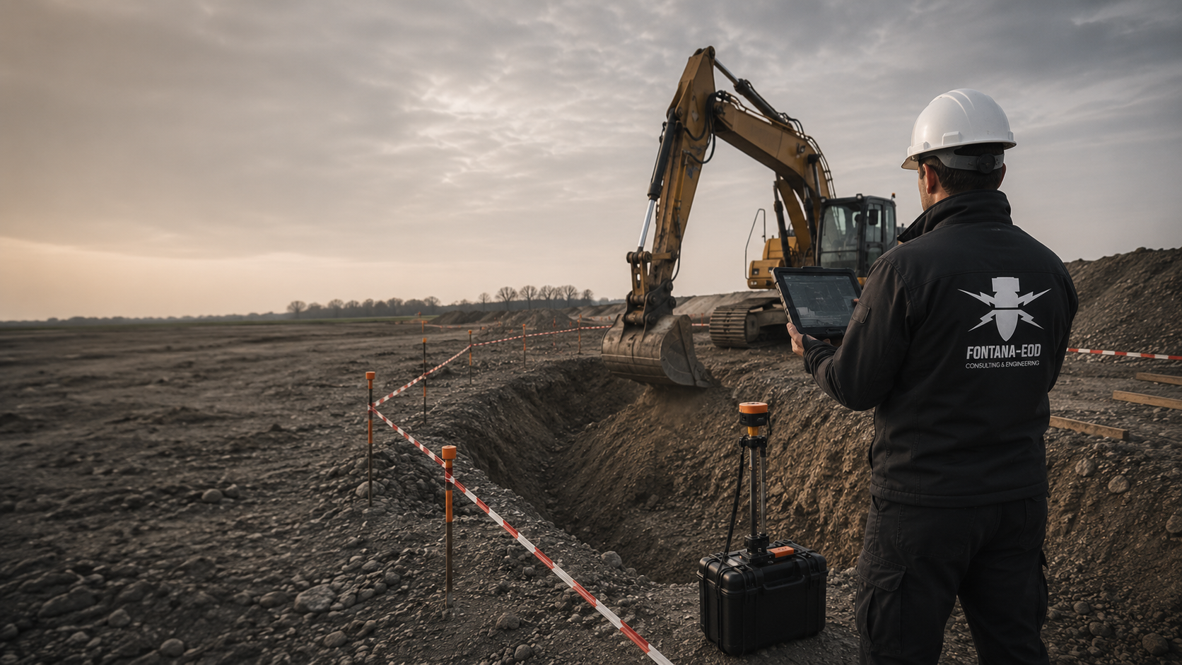
Reinforced concrete, sheet piles, rails, bundles of services, machinery foundations and metal-rich fill can make magnetometry unusable in parts of a site. If these zones lie within the later excavation, a further technically suitable method is defined. An ordnance survey during construction requires that it can adequately assess the actual space affected by the works.
The technical survey and specialist decision take place before each removal of ground. The defined layer is then excavated with additional visual checks. The sequence is repeated down to the planned formation level. Layer sequence, excavator operation, stop points and reporting channels are agreed before work begins. The record connects the assessment to the section actually worked and the remaining limitations.
Understand excavation supervision requirementsDescribe the planned intervention by location and depth. Different construction phases or local deeper sections remain identifiable on the plan. This information provides the basis for comparison with existing findings.
Provide previous reports and project-specific information in full, with their annexes. Their spatial reference determines which information can be used for the current construction task.
Identify access, existing installations and known limitations of the working area. Technical preparation can then clarify what conclusion is achievable under the actual conditions and what further information is needed.
An open construction site has different requirements from land beside tracks or reinforced-concrete structures. Before the survey, the ferromagnetic objects sought are identified and it is assessed whether their signals may be recognisable despite the existing interference sources.
Area mapping, repeat measurements of selected anomalies and depth-related assessment are different tasks. Each requires appropriate sensor arrangements, survey tracks, control measurements and acceptance criteria. Planning and costing must therefore establish whether the first task is to assess a continuous area, check an existing anomaly list or prioritise a limited number of suspect points for the next stage.
On open, sufficiently level sites with little magnetic interference, magnetometry can demonstrate its strengths as an area survey method. Several sensors, a close grid and GNSS-supported positioning allow dense mapping of local field changes.
Before surveying, the area, target object, expected depth, vegetation, terrain steps and visible metal sources are assessed. Edge zones near fences, buildings or traffic areas are treated separately.
Services, rails, fences, crash barriers and existing cables can generate elongated magnetic fields along a route. These mask local anomalies and change the usable working width.
The route is divided into comparable sections. Interference zones, sensor separations and required additions are documented for each section so that conclusions are not applied indiscriminately along its entire length.
Metal-rich fill can produce a high density of small anomalies. Signals then overlap, and larger or deeper target objects can no longer be reliably separated from near-surface scrap.
The target object, spatial signal overlap, clearance objective and possible further investigations are considered in advance. Dense metal coverage can also limit TDEM. An ordnance survey during construction is only an option where it is technically suitable for the actual space affected by the works; the technical assessment and decision take place before each removal of ground.
Reinforced concrete, foundations, sheet piles, shafts and technical installations generate dominant magnetic fields. In their immediate vicinity, magnetometry cannot provide reliable conclusions about smaller or deeper target objects.
These zones are delimited during planning. Ground-penetrating radar, TDEM, point-specific investigation or specialist excavation supervision are added only where their own physical information can genuinely improve the answer to the project question.
On large sites accessible to vehicles, a multichannel system can record several parallel survey lines simultaneously. This requires controlled sensor height, a suitable driving track, adequate positioning quality and site preparation without interfering vehicles or loose metal parts.
Higher area productivity does not replace quality control. Track spacing, overlaps, sensor offset, control profiles and data consistency are documented, with repeat measurements where irregularities are found.
For comparable procurement, the survey area, measured component, number of sensors, track spacing, positioning method, control measurements, data formats, interpretation and documentation scope must be specified. A general item described simply as “magnetometry” leaves essential quality characteristics undefined.
The evidence due should make clear which areas were surveyed under which conditions, where magnetic interference dominated and what technical follow-up decision arises from the anomalies.
Magnetic data respond to the target object, sensor arrangement and magnetic environment. High instrument sensitivity alone does not guarantee reliable conclusions across an area. Survey geometry, positioning, interference sources and interpretation must be planned together.
Edges, lateral interference sources, obstacles, changing sensor height and interruptions are considered in the survey plan. They affect both practical acquisition productivity and the reliability of later interpretation. Where tracks cannot be followed correctly or rails, reinforcement, fences or vehicles dominate the magnetic field, the area must be identified spatially and linked to a suitable additional measure.
Execution requires safe access, coordinated traffic and operating conditions, and clear lines of instruction and reporting. Soil moisture, hard surfacing and existing installations inform method selection. Signal quality and limitations remain documented alongside the depth actually surveyed or worked.
Only objects with a sufficient magnetic effect produce a usable signal. Non-ferrous metals without relevant ferromagnetic constituents are not recognised as separate targets.
Object mass, shape and spatial position, together with induced and remanent magnetisation, determine the strength and form of the anomaly. An unfavourable orientation can substantially weaken the signal.
Anomaly strength decreases sharply as distance increases. Vegetation, uneven ground, chassis movement and changing survey height can therefore affect the comparability of adjacent tracks.
The grid and direction of travel must suit the expected object size. Excessive spacing can miss narrow anomalies; systematic track offsets create positioning and interpretation errors.
Rails, fences, services, vehicles, reinforced concrete, shafts, construction equipment and metal-rich fill can mask local anomalies or completely dominate the usable survey area.
Fluxgate, total-field and multichannel systems record different quantities. Selection, sensor spacing, gradiometer arrangement and calibration are matched to the area and target object.
Profiles, edge interference and derived target coordinates use the same survey reference. Positioning errors can prevent anomalies from being reliably relocated or cause them to be assigned to the wrong area.
Raw data, control profiles, survey gaps, sensor failures and areas dominated by interference are documented. Uninterpretable zones remain visible and are not concealed by blanket statements about the site.
The anomaly map is accompanied by a report describing the survey system, areas examined, data quality and known interference. Designers and site management can then see the basis of the assessment. To make the technical reasoning traceable, control measurements, correction steps and the criteria used to prioritise anomalies or classify them as known interference sources are also documented. This shows which decisions follow directly from the survey data and where additional information or investigations are needed. Repeat measurements and positioning checks are also documented so that subsequent target points can be reliably related back to the project reference. Survey gaps and magnetically disturbed edge areas remain visible as separate area categories.
Interpretation distinguishes survey areas without anomalies, zones dominated by magnetic interference and prioritised anomalies. Each group calls for a different approach in the subsequent project. If area boundaries, reference corrections, filters or assessment rules change during processing, it also remains traceable which data and map version represents the status handed over.
The project name, survey polygon, route chainages, parcel, reference system and profiles actually recorded are clearly linked. Edge zones near structures and unsurveyed areas are traceable on the maps.
Historical indications, authority documents, known finds, planned intervention depth and expected ferromagnetic targets underpin method selection and later anomaly prioritisation.
Magnetometer type, measured component, sensor number and spacing, track spacing, acquisition speed, positioning method, survey height and control profiles are described so that data acquisition can be understood technically.
Surface conditions, vegetation, terrain steps, services, fences, rails, vehicles, reinforcement, buildings and other magnetic influences are documented spatially. Sources that change over time are assigned to the affected profile section.
Relevant signals are georeferenced and assessed for shape, amplitude, spatial repeatability and possible interference source. Depth or size estimates are presented with the model assumptions on which they are based.
The report describes which areas were interpretable under the documented conditions, what interference dominates and whether exposure, an additional survey, a depth check or specialist excavation supervision is required. If target points are subsequently exposed or cleared, findings and clearance records document the actual work and outstanding points.
The report must show the source data and measurements on which the assessment is based. The field record, positioning data and processing steps are therefore documented. The documentation distinguishes raw measurements, the technically interpretable area and the spatial reach of the specialist conclusion.
The historical assessment, current site plan, existing services, ground information and project requirements are assembled with clear version identifiers. This makes it possible to see the basis on which the grid and target definition were chosen.
Survey date, sensors, configuration, calibration, personnel, weather, site conditions, magnetic objects, obstacles and deviations are recorded during the work.
The original magnetic field data are retained as the basis for verification. Track corrections, drift processing, filtering and the combination of several sensors are documented.
Relevant anomalies, linear interference sources, disturbed edge areas, survey gaps and work boundaries are shown within a consistent spatial reference.
The assessment distinguishes the measured finding, modelling and recommendation. It states which project question was answered and what measures are appropriate for unresolved or ordnance-relevant areas.
Reports, plans and data are prepared so that the client, designers, site management and, where appropriate, responsible authorities can use the same work status and limitations. Later survey and clearance records are linked to this initial assessment through anomaly identifiers, coordinates and plan versions.
Magnetic data are sensitive to the actual survey environment. Sensor spacing, orientation, moving metal sources and temporal changes in the magnetic field must therefore be considered alongside the expected ferromagnetic target object.
Reliable acquisition combines a survey grid with few gaps, field checks and traceable data processing. Only after drift checks, positioning checks and comparison with known interfering bodies does a magnetic field deviation become a target point requiring project-specific assessment.
The basis for suspicion, expected object size, intervention depth and desired follow-up decision determine the required survey sensitivity. Existing plans, earlier survey reports and authority documents are checked against the current intervention. Incomplete annexes or spatial inconsistencies are identified before survey planning. Where historical knowledge is missing, the necessary research or aerial photograph assessment is added specifically. The historical assessment is compared with current area boundaries and interventions and provides a traceable basis for further investigation.
Rails, fences, reinforcement, vehicles, services, industrial building structures and iron-containing fill are located as potential influencing sources.
The single- or multichannel system, sensor height, probe spacing and carrier type are matched to site size, terrain, target resolution and separation from interference.
Profile direction, track spacing, coverage, reference points and control areas are planned to maintain continuous spatial anomaly mapping.
The survey team keeps sensor handling and speed as constant as possible and immediately identifies deviations, obstacles or changes in metal conditions.
Temporal field changes, offsets between tracks, sensor errors and known edge interference are checked without removing relevant object responses through unsuitable filters.
Amplitude, dipole characteristics, spatial extent and surroundings are used to estimate location and possible depth technically and to prioritise targets.
The anomaly plan, point list, survey gaps, edge influences and recommended follow-up measures are brought together clearly for design and construction.
Magnetic data are indirect measurements. They show deviations in the local magnetic field, not a scale outline of an object. Reliable interpretation separates the raw signal, spatial processing, model assumptions and specialist conclusion.
Ferromagnetic bodies change the Earth’s natural magnetic field. Depending on the system, field components, total intensity or gradients between sensors are recorded. When many readings are acquired along closely spaced tracks and combined with accurate positioning, they form a spatial pattern of positive, negative or dipole-like anomalies.
Anomaly shape and strength do not depend on the object alone. Depth, mass, shape, orientation, induced and remanent magnetisation, sensor height and nearby interference sources act together. Inversion for size and depth is therefore inherently ambiguous and must be checked for plausibility against the basis for suspicion, survey environment and, where needed, additional methods.
An area assessment does not simply mark individual peaks. What matters is whether the anomaly pattern is consistent across adjacent tracks, distinguishable from linear or extensive interference sources and reproducible in position during control measurements. Positive and negative field components, gradient pattern and spatial width are considered together. This distinguishes isolated data errors, track offsets and edge effects from plausible local sources without inferring an object type from shape alone.
Specialist prioritisation is then related to the planned ground intervention. An anomaly within the space affected by a pile, service trench or excavation may require a different follow-up measure from an equally strong signal outside the construction boundary. At the same time, an apparently clear map must not be generalised across areas where fences, reinforced concrete, vehicles or metal-rich fill dominated the magnetic response. The surveyed area, interpretable area and project-specific scope of conclusions are therefore stated separately.
Control profiles, return tracks or targeted repeat measurements are used for quality assurance. If anomaly position and signal pattern agree under comparable conditions, this supports spatial plausibility. Differences may instead indicate track offset, changed sensor height, moving metal sources or technical interference. These findings are clarified before a target list is produced and are not concealed by subsequent smoothing.
Site preparation is also part of survey quality. Loose metal parts, parked vehicles, construction equipment or temporary fences can cause avoidable interference. Vegetation and uneven ground affect sensor height and therefore signal strength. The ability to clear obstructions, vehicle access and permitted working corridors are therefore agreed before work begins. Areas that cannot be surveyed in comparable geometry receive their own assessment rather than a calculated continuation of neighbouring areas.
For subsequent investigation of findings, anomalies are not ranked by amplitude alone. Spatial shape, dipole characteristics, position relative to the intervention, distance from known interference sources, model stability and historical plausibility are considered together. This multistage prioritisation reduces incorrect assignments without treating magnetometry as a means of certain object identification. If relevant uncertainty remains, the appropriate control or follow-up measure is explicitly identified.
Gradient measurements suppress large-scale field changes and emphasise local sources. Total-field systems record the absolute field strength. The appropriate quantity depends on the target object, system configuration and interference environment.
A single ferromagnetic body can produce a pair of positive and negative anomalies. The location and alignment of this pattern are influenced by the Earth’s magnetic field, object orientation and remanent magnetisation.
As distance increases, the anomaly weakens markedly and becomes spatially broader. Changes in sensor height caused by vegetation, uneven ground or chassis movement can therefore affect the comparability of survey tracks.
Track spacing and positioning quality determine whether an anomaly can be fully recorded and later relocated on site. Survey gaps or offset return tracks require controlled repeat measurements.
Analytical methods and dipole models can estimate location, apparent depth or magnetic moment. Results remain dependent on model assumptions and are not presented as direct measurements of the object.
If an unresolved magnetic anomaly intersects the proposed intervention, it is assigned a work priority based on location and finding characteristics. Depending on the project, this is followed by control measurement, target investigation, exposure, deep-ground survey or specialist work during construction.
Magnetometry’s strength is the sensitive, passive detection of ferromagnetic bodies. Other methods become necessary where the focus is on non-ferrous metals, subsurface structures, deep individual ground interventions or working areas that cannot be surveyed with the proposed technique.
Specific benefit: dense and economical mapping of magnetic anomalies on open sites with adequate separation from interfering iron masses.
Assessment limitation: magnetic anomalies are ambiguous; material quantity, orientation, remanence, depth and nearby interfering bodies jointly influence the signal.
Specific benefit: additional information on electrical conductivity, including conductive non-ferrous metals and selected anomalies with an unclear magnetic response.
Assessment limitation: services, reinforcement, large metal surfaces and changes in ground conductivity produce their own electromagnetic responses; range depends on the system.
Specific benefit: representation of structural remains, service corridors, fill boundaries and other subsurface structures that can explain magnetic signals.
Assessment limitation: the radar image depends strongly on moisture, conductivity and frequency; a reflection does not provide a reliable identification of material or ordnance.
Specific benefit: delimits suspected areas and provides indications of expected object types, links to events and the priority of individual project sections.
Assessment limitation: source analysis describes a suspected hazard, but not an object’s current position or its detectability under present site conditions.
Specific benefit: brings magnetic sensors closer to deeper targets and allows point-specific assessment for drilling or foundations.
Assessment limitation: borehole position, spacing, casing and design depth determine the space examined; results do not automatically apply to the area between the assessment geometries.
Specific benefit: technical survey and specialist decision before each removal of ground in suitable excavation areas. Layer-by-layer excavation with additional visual checks then follows, with a new survey before the next layer. Visual observation alone does not replace this technical assessment.
Assessment limitation: conclusions and evidence relate to the excavation layers supervised and must be coordinated with the equipment, stop points and communication of finds.
Before the survey, it must be clear who makes the site accessible, removes moving interference sources and reports changes on the construction site. The survey team and data interpreters need current plans and the same area boundaries.
Defines the project area to be surveyed, planned ground intervention and intended use of the result. Historical documents, current site plans and known metal installations are provided in full.
Defines the target object, required area coverage, sensor arrangement, track spacing, positioning quality and acceptance criteria. Edge zones and areas likely to have inadequate separation from interference are considered in the survey plan.
Provide accessible survey tracks and remove moving metal sources where operationally possible. Vehicles, containers, machinery states and changes during acquisition are coordinated with the survey team.
Check probes, sensor height, track guidance, drift and positioning data. Interpretation distinguishes local dipole anomalies, linear infrastructure, edge effects and extensive magnetic interference.
Assesses anomalies against the basis for suspicion and the planned intervention. Identifies areas that cannot be adequately surveyed and recommends the further investigations or work required.
Are involved where further investigation leads to a specific suspicious object. Responsibility and reporting channels depend on the location and actual circumstances of the find.
The responsibilities of KBD, KMBD or KRD and local public-order authorities vary by location. Building control may be involved in the construction project. Existing requirements are supplied with dates and area references; competent bodies and reporting arrangements are clarified for the actual project site.
Magnetic mapping is initially a passive geophysical measurement. Nevertheless, the project assignment must plan ahead for how unsurveyable zones, prioritised anomalies and possible follow-up services involving ground intervention will be handled.
The Baufachliche Richtlinien Kampfmittelräumung describe magnetometry as a method for detecting and mapping distortions of the Earth’s magnetic field and contain technical specifications for digital surveys on foot and with vehicle-mounted systems. The service specification should particularly address sensors, track guidance, area coverage, spatial reference, control procedures and interpretation records.
Even a survey to search for munitions must be considered under explosives legislation; searching is explicitly covered by § 1b paragraph 1 no. 3 letter d SprengG. Commercial work requiring a licence needs the appropriate authorisation under § 7 SprengG; responsible persons perform activities requiring a certificate of competence within the framework of § 20 SprengG.
DGUV Information 201-027 supports risk assessment for searching for, exposing, identifying and recovering ordnance. A magnetic target list therefore becomes a measure involving ground intervention only after separate work preparation.
The First Ordinance to the Explosives Act (1. SprengV) includes requirements for specialist knowledge and state-recognised courses. For the magnetic survey and possible follow-up work, the required qualifications are matched to the scope actually commissioned.
DGUV Regel 113-003 concerns dismantling or destroying explosives or corresponding objects and also covers disposal of discovered munitions. Applicability is assessed according to the specific activity; passive magnetic mapping and the later treatment of a find remain described as different tasks.
Site conditions, sensor separation and lateral iron masses are assessed before commissioning; persistently affected zones receive a different work strategy.
The survey grid, channels, sensor height, positioning, drift checks, raw data and anomaly list are specified as a scope that can be checked for acceptance.
Coordinates, prioritisation and local setting-out must align before an anomaly is exposed or incorporated into the construction sequence.
The interpretable area, magnetically disturbed edge zone, survey gap and target point requiring further work are marked differently in the final record.
The assignment identifies the target object, survey area, required coverage, sensor and positioning requirements, and the format of the data and maps to be delivered.
Moving interference sources, changed construction conditions and sensor separations that cannot be maintained are recorded immediately so that they do not later appear as unexplained anomalies.
Before ground intervention, qualifications, protective measures, working methods and the local reporting procedure are established for the selected target points.
Survey height and positioning data are recorded together with magnetic field values. They help compare adjacent profiles and relocate anomalies on site. Changes in sensor handling and local metal sources are assigned to the affected survey tracks.
Sensor spacing, track guidance, survey height and positioning are matched to the target object and required resolution. Obstacles, disturbed edge zones and survey gaps are documented during fieldwork.
Assess the area survey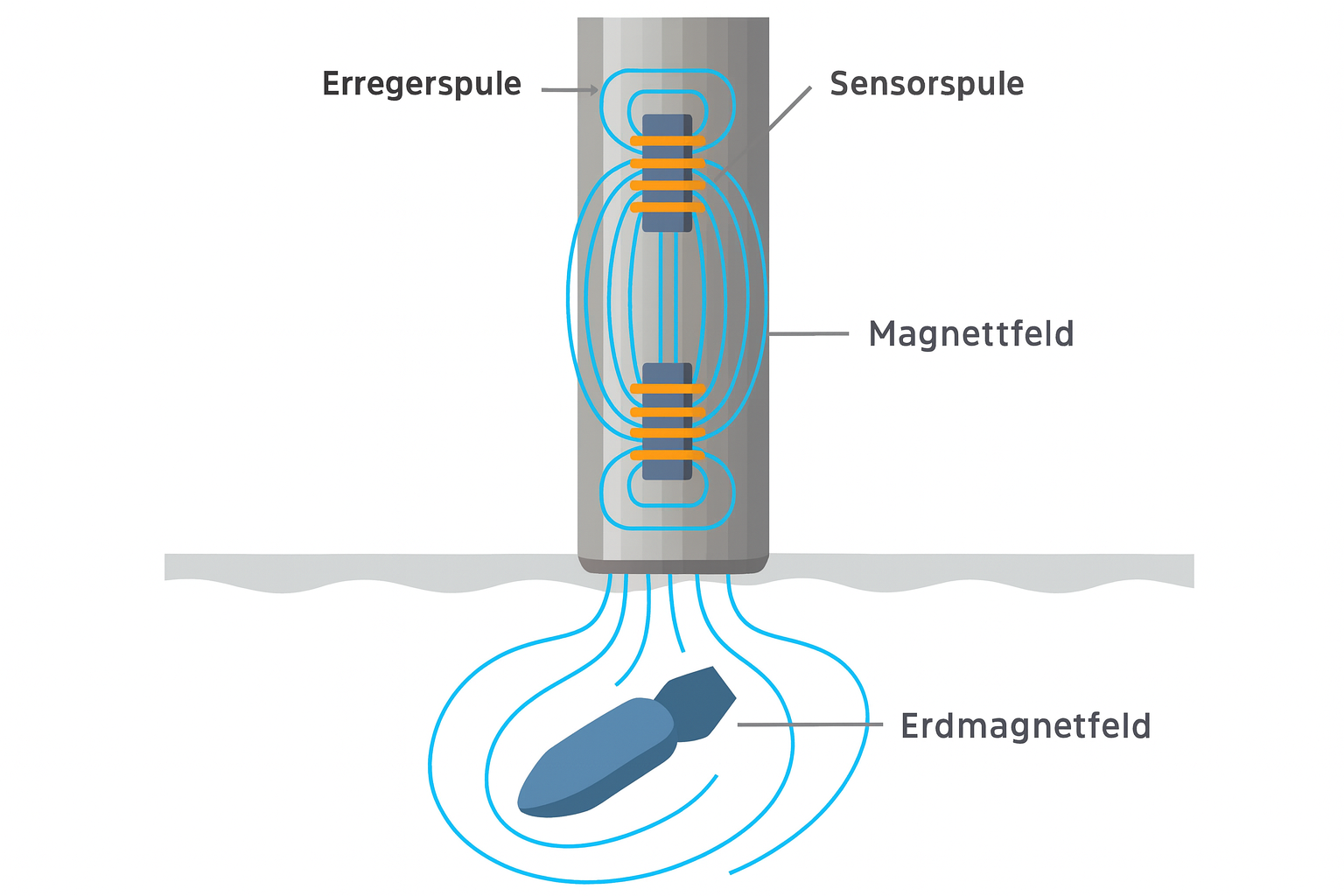
The measured anomaly results from the interaction of the Earth’s magnetic field, induced and remanent magnetisation and the object’s spatial position. It is not a direct representation of the object’s outline.
Examine survey conditions in detail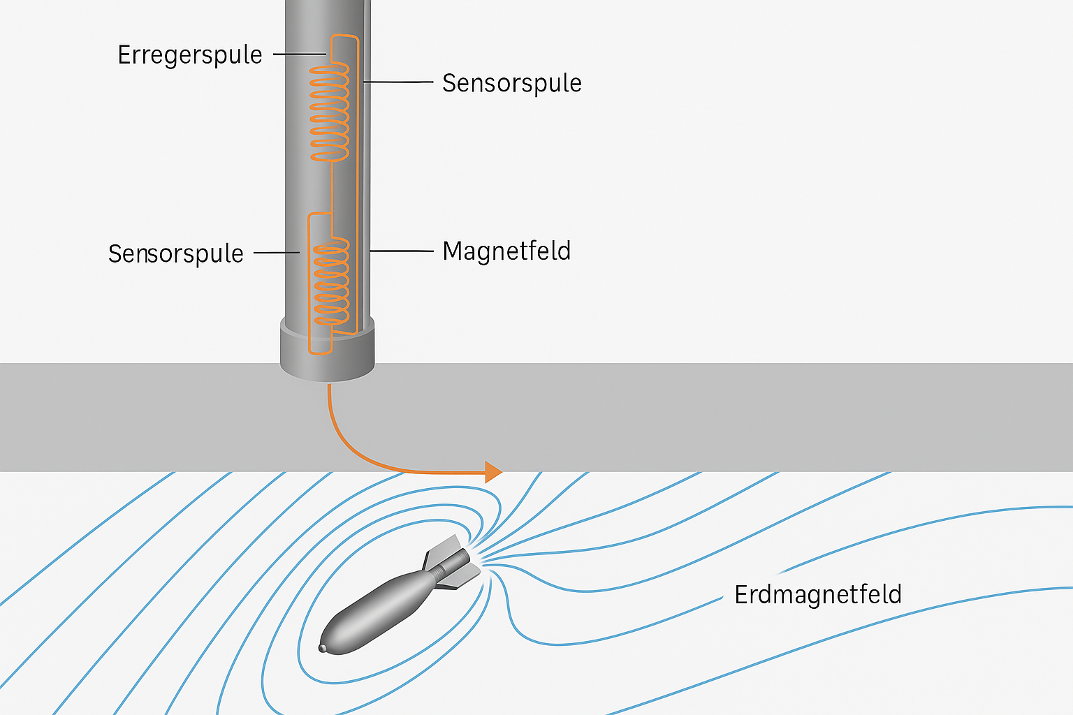
A constant distance from the ground and even track guidance are essential for comparable readings. Vegetation, uneven ground and technical obstacles are recorded as quality factors.
Compare survey methods and influencing factors
Dipole shape, amplitude and extent are considered within the survey grid. Depth or size estimates require model assumptions, which are identified traceably in the report.
Document anomalies traceably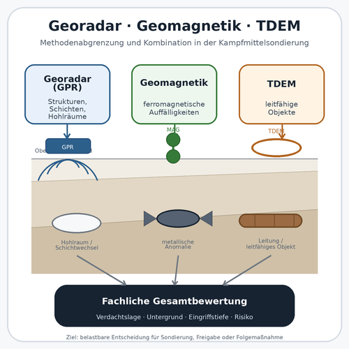
Magnetometry assesses ferromagnetic anomalies, TDEM conductivity and ground-penetrating radar structural contrasts. Combining them is only useful if each dataset reduces a specific uncertainty.
Compare additional methods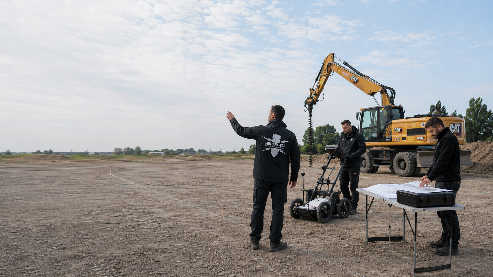
The survey grid, accessible areas and expected interference are assessed before the quotation. Areas where magnetometry is unlikely to be sufficient are considered when planning additional investigations.
Send project records for assessment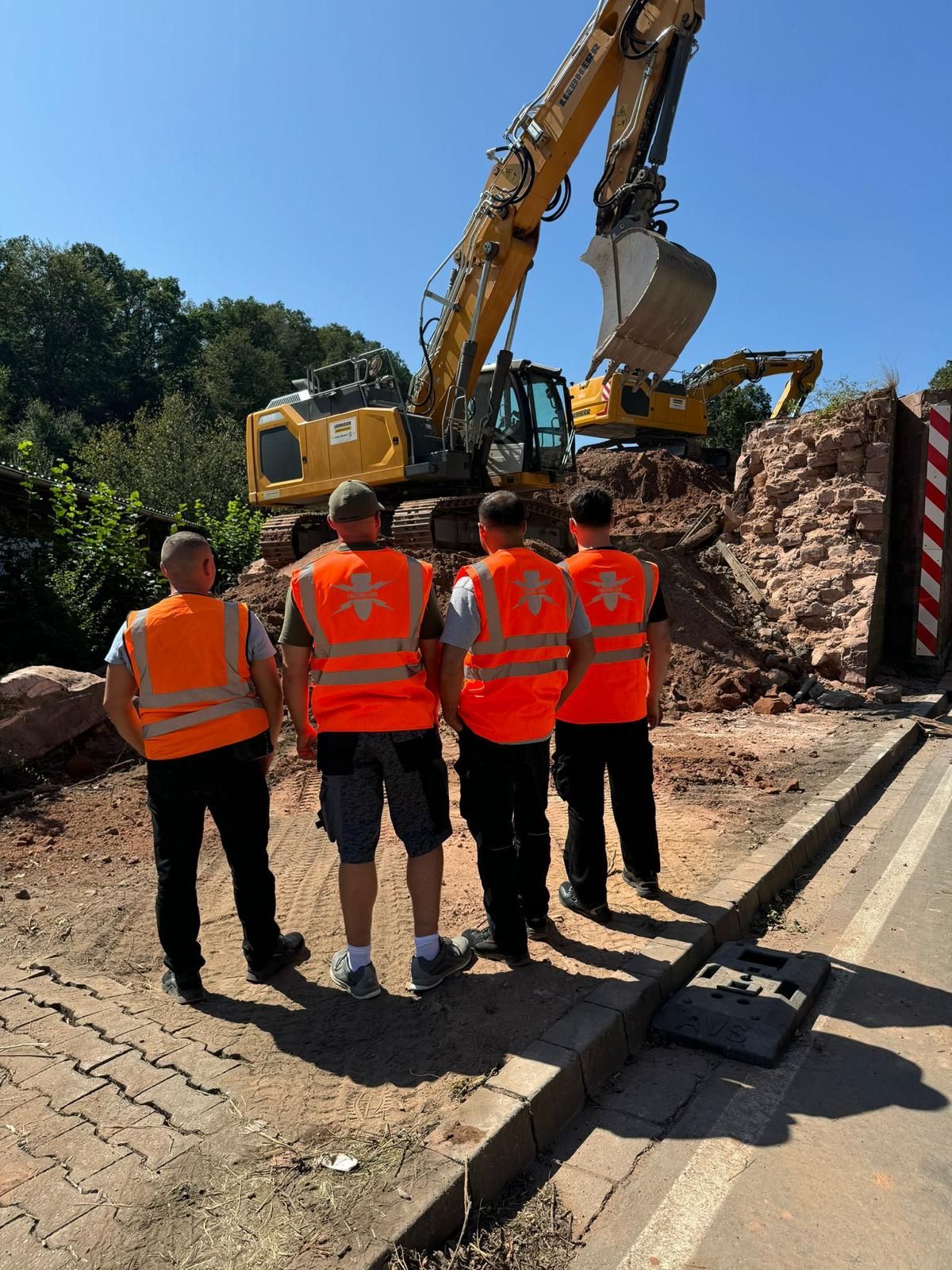
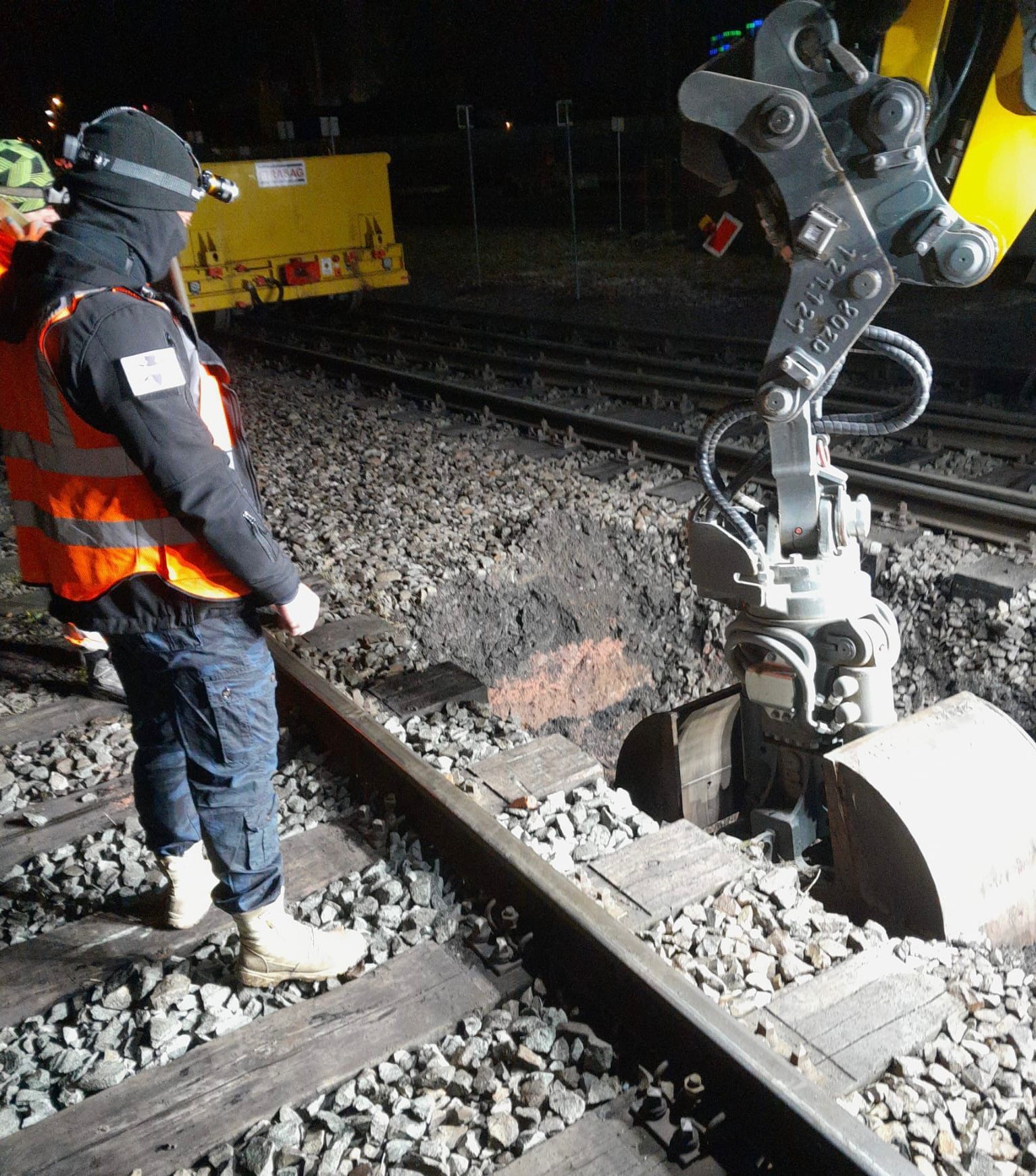
Magnetic results lead to different decisions depending on site quality: explainable infrastructure is documented, relevant dipole anomalies are prioritised and zones dominated by strong magnetic interference are assigned an additional method or a specialist solution during construction.

Assemble clarification of the suspected hazard, detection, target investigation, excavation, recovery and documentation according to the project status.
View all servicesCombine magnetometry, TDEM and ground-penetrating radar according to the physical quantity sought and the survey quality actually achievable.
Plan a surface surveySurvey selected areas or anomalies using an active electromagnetic method where material conductivity can provide additional information for decisions.
Assess TDEM as an additional methodInvestigate service corridors, foundations, layer changes or made ground where they are relevant to interpreting the magnetic field map.
Assess radar investigationSupplement surface magnetometry for piles, sheet piles or drilling with suitable depth-related assessment geometry.
Prepare drilling points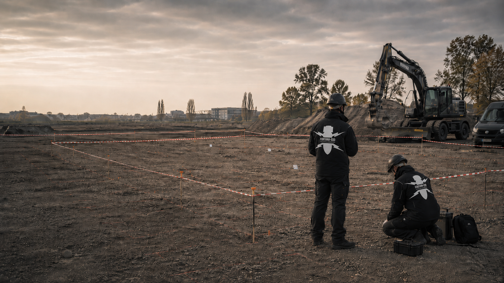
Organise a larger number of relevant target points with a defined clearance objective, work limits, quality checks and records of findings.
The area clearance process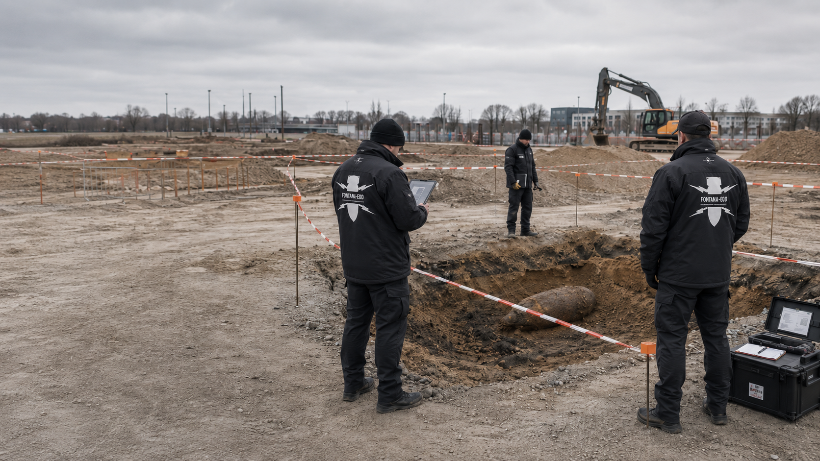
Coordinate the find circumstances, condition, working environment and responsible interfaces for further handling of a confirmed item of ordnance.
Clarify ordnance recoveryAssign raw data, survey tracks, anomaly lists, modelling, interference areas and work status clearly to the project file.
Agree the documentation
Take account of site access, operating environment, route arrangements and construction sequence for railways, energy, civil engineering, industry or municipalities.
Select a construction taskBefore the survey, the basis for suspicion, target object, expected depth, sensor arrangement, track spacing, positioning method and interference environment are therefore checked. If magnetic conclusions are insufficient for the planned intervention, TDEM, ground-penetrating radar, deep-ground or downhole surveys, target investigation or specialist excavation supervision are considered as additions.
FONTANA-EOD matches the magnetic survey to the basis for suspicion, target object and planned ground intervention. The agreed scope describes the area, conditions and documentation needed. The later conclusion is related to the specialist work actually performed. Unworked or insufficiently interpretable areas remain identifiable in the documents.
Discuss the investigation taskThe designers provide location, depth and reference levels. Changes from the previous version are identified. This makes it possible to understand which construction task underlies the survey plan and whether new works still fall within the described survey scope.
Access and available working areas are clarified with site management or the operator. Known installations and organisational restrictions form part of preparation. An inaccessible area is not included in the result simply because it is close to an examined subarea.
The specialist interpretation describes the survey’s conclusions and the next steps derived from them. Site management and designers use the report and annexes together with the other project documents. A single result line should not conceal spatial limits or remaining technical questions.
Result plans and the report remain linked to their plan version. If the project is later extended, this basis is compared with the new intervention. Existing findings can then be reused without silently changing their original reach.
For a sound tender, the survey objective, ferromagnetic target object, required depth range and spatial work scope are established before selecting the sensors. The specification also includes sensor type, measured component, sensor arrangement, survey height, track spacing, spatial reference, quality checks and the data to be delivered. This makes it clear whether area magnetometry, a targeted repeat survey or a combination with other methods can answer the project question.
Send the current intervention plan, existing information and earlier reports. Unresolved depths or alternatives are explicitly identified. The initial discussion can then clarify which task is already well defined and what information must be added before the survey scope is established.
Site management identifies access, area boundaries and known local restrictions. The specialist company explains the requirements of the proposed investigation. Before work begins, it is checked whether the agreed conditions are actually present. Changes have a clear communication route so that execution and documentation address the same situation.
The report and result plan describe which areas were examined and what questions remain. The further activities required are assigned to the specific project. The project team aligns the next step with these technical conclusions while continuing to consider the other construction and operational conditions.
For an additional foundation or altered service, location and depth are compared with the earlier documentation. A known site name alone is insufficient. The earlier specialist work retains its original scope; any additional requirement is described separately.
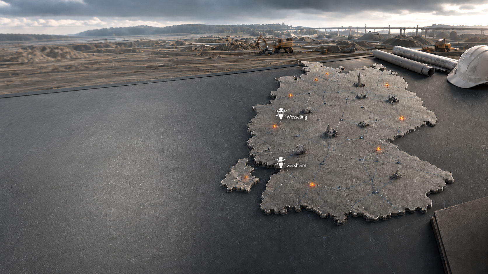
State the location, property or construction section and a reachable project contact. Use clear identifiers for several areas. The regional overview helps with orientation. The specific groundworks, available findings and local conditions are also decisive for the investigation.
Existing information and earlier survey documents are sent with their associated plans. Identify their original spatial reference. A conclusion about an adjacent area or a different intervention depth is used only after technical comparison. Unresolved requirements remain identifiable for further planning.
A magnetic anomaly does not identify ordnance. Scrap, services, fences, rails, vehicles, reinforcement, sheet piles, structural remains and geological influences can produce similar or overlapping signals. Object orientation and remanent magnetisation also affect the anomaly’s shape and strength.
Alongside the survey, the specialist assessment considers existing knowledge and the specific construction task. The report and result plan show the further steps derived from it. An anomalous image is not used to identify a particular object without its associated technical context.
Explore results and terminologyThe suitability of an additional method is clarified against the survey objective and local conditions. An enquiry can therefore start with the conclusion needed instead of fixing a single instrument-based method whose requirements for the site have not yet been clarified.
Understand the service scopeThe area, depth, plan version and limitations form part of a survey’s conclusions. Keep the annexes with the report. For later groundworks, this scope is compared with the new project. An abbreviated completion notice does not replace the spatial reference.
Explore results and terminologyTechnical information
The brochure explains magnetic surveys for explosive ordnance detection. It describes preparation, handling of interference and specialist assessment of anomalies.

Ferromagnetic bodies change the Earth’s local magnetic field. Magnetometers record these deviations along profiles or across an area in several tracks. The georeferenced values are processed into a magnetic field or gradient map, in which spatially related anomalies are assessed by specialists.
The method is particularly suitable for objects with sufficient ferromagnetic mass, such as iron-containing ordnance or larger steel bodies. However, signal strength and anomaly shape also depend on depth, orientation, magnetisation and distance from the sensor. Conductive non-ferrous metals without a significant ferromagnetic component are not detected as magnetic targets in their own right.
A magnetometer measures a magnetic field component or the total field strength. A gradiometer measures the difference between spatially separated sensors, thereby emphasising local field changes. The appropriate arrangement depends on the target object, site conditions, separation from interference sources and the required sensitivity to regional or local influences.
We check whether the method is suitable, wherever possible before tendering and before any ground intervention. The basis for suspicion, target object, working area and interference sources are checked first. Survey planning, spatially referenced data acquisition, quality control and specialist interpretation follow. Anomalies, survey gaps and limitations are handed over to designers and site management together with the next action required. On suitable sites, multichannel systems can record several tracks simultaneously; sensor height, positioning and accessibility remain decisive.
Rails, steel fences, vehicles, reinforcement, sheet piles, services, shafts, containers, construction equipment and iron-rich surface scrap can mask target signals or produce extensive edge effects. Moving metal bodies are particularly critical because they can affect different profiles differently and thereby cause apparent anomalies.
Location, apparent depth and magnetic moment can be estimated from the field pattern, amplitude, sensor arrangement and model assumptions. However, the solution is not unique: a smaller shallow source and a larger deeper one can produce similar survey patterns. Depth and size estimates must therefore be presented together with model quality and the interference environment.
Known infrastructure, edge effects and repeatable profile information are checked first. Remaining anomalies are prioritised by location, dipole characteristics, amplitude, relation to the suspected hazard and proximity to the ground intervention. The target list contains coordinates, the assessment basis and the recommended next action, such as repeat measurement, a depth check or exposure.
If a suspicious object is found, stop work. Do not touch or move it. Leave the immediate area, warn others without putting yourself at risk and, in Germany, notify the police on 110; outside Germany, use the local emergency reporting arrangements. The competent authorities determine further action according to the actual find.
The area polygon or route corridor, basis for suspicion, nature and depth of the intervention, current as-built and utility plans, information on vegetation, terrain, surfacing and magnetic interference sources, and the required data and report format are needed. For existing surveys, raw data, sensor arrangement, survey height and correction steps are particularly important. Existing authority information and conditions are provided with complete annexes, dates and spatial scope; information and reporting channels are clarified for the specific project location.
Cost and processing time depend, among other things, on site size, access, interference, the required grid, checks and interpretation scope. Quotations can only be compared meaningfully where the survey and evidence objectives are comparable.
To plan a magnetic survey, it must be clear whether the relevant area can actually be recorded with sufficient separation from interfering iron masses. The location and type of metal infrastructure are therefore as important as site size and the suspected hazard.
For existing magnetic data, raw data, channels, sensor arrangement, survey height, driven tracks and corrections used are needed alongside maps. Only then can it be checked whether the target list is based on a complete and technically traceable dataset.
Provide a clear boundary of the areas accessible on foot or by vehicle, planned construction sections and the location of fences, tracks, buildings, sheet piles, steel structures and other lateral interfering bodies.
For routes, chainage, working width, crossings and bottlenecks are helpful. On larger sites, priorities and required handover dates should be stated separately.
Describe which ordnance or object class is derived from the basis for suspicion and what space will later be affected by excavation, utility construction, dismantling or foundations.
The expected object size and required depth horizon influence sensor height, grid, channel count and whether surface magnetometry alone may be sufficient.
As-built and utility plans and information on reinforcement, scrap, metal-rich fill, vehicle movements, machinery, containers, rails and technical installations are needed.
Operating times also matter: moving metal bodies or changing installation states during acquisition can affect profiles differently and reduce the comparability of readings.
For a preliminary assessment, the site plan, documents on the suspected hazard, planned intervention, site photographs and an overview of visible metal sources are often sufficient. For third-party surveys, the sensor type, channel arrangement, survey height, profile spacing, positioning method, drift correction, filtering and available raw data should also be stated.
Vegetation, vehicle accessibility, terrain shape, surfacing, obstacles and lateral separation from fixed metal bodies.
Single- or multichannel arrangement, magnetometer type, sensor height, probe spacing, carrier platform and positioning solution.
Rails, fences, reinforcement, services, vehicles, installations, scrap and iron-containing fill.
Anomaly mapping, target list, depth estimation, tender information or preparation of clearance or construction work.
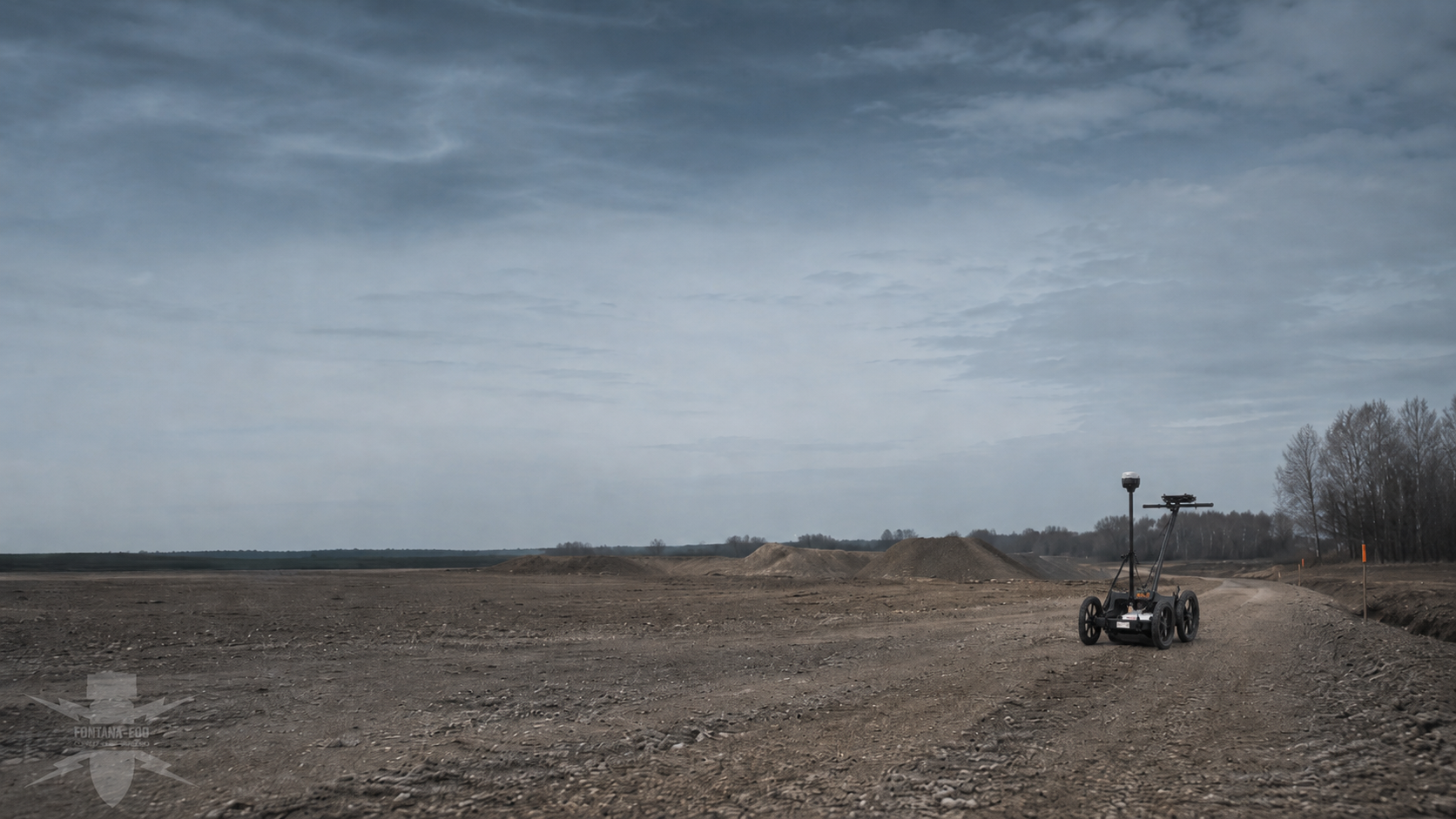
Whether historical aerial photograph analysis, explosive ordnance surveying, surface surveying using GPR, magnetometry or TDEM, deep-ground surveys, downhole surveys, excavation supervision, area clearance or ordnance recovery is needed depends on the location, ground disturbance, depth, ground and existing documents. An early ordnance assessment provides clarity for tendering, programming, occupational safety and construction.
FONTANA-EOD combines its Section 7 SprengG licence, specialists holding Section 20 SprengG certificates of competence, suitable survey and clearance methods, and traceable documentation. Send the site plan, depth of ground disturbance, construction phase and existing documents for an initial technical assessment.


