Project pathway
The quickest route to the right decision.

For developers, designers and geotechnical consultants, GPR can add information about structures beneath asphalt, fill or old foundations to an explosive ordnance investigation. FONTANA-EOD assesses suitability against the survey objective, soil, moisture, depth and sources of interference, plans data acquisition and interprets the radar profiles. Send a site plan, the proposed excavation depth and existing records so that the survey design and any additional investigations can be agreed.
Match ground conditions to the survey objective.
Define the survey grid and antenna.
Interpret signatures with specialist judgement.
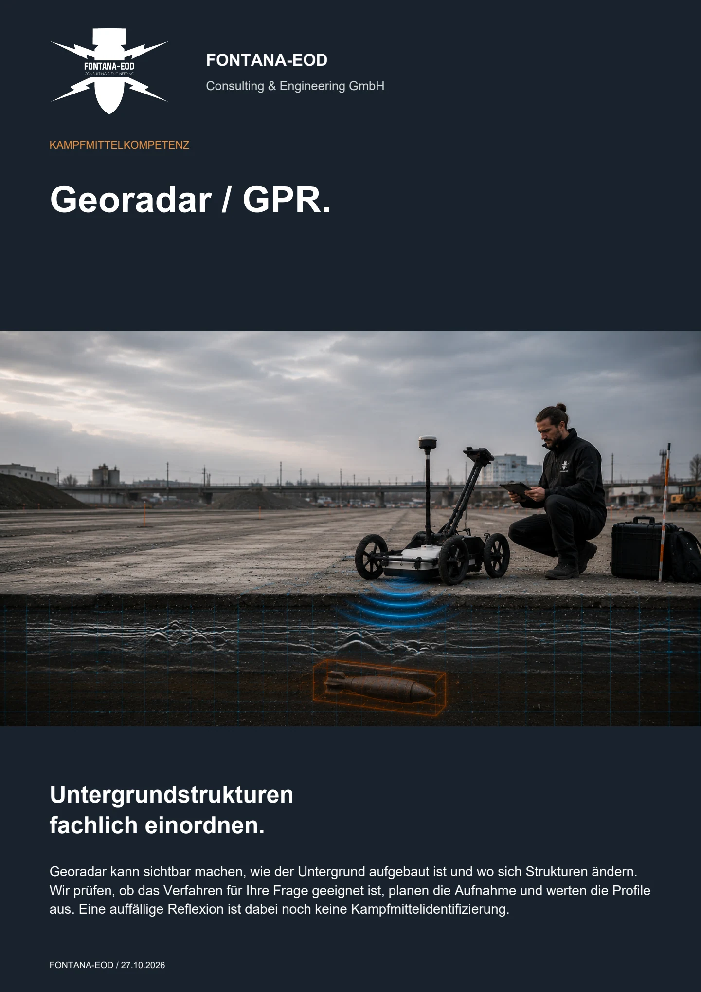
GPR adds information about layers, buried infrastructure and other subsurface structures to an explosive ordnance investigation. This requires interpretable radar profiles. Before surveying, we assess the ground, survey objective and required depth. An anomalous reflection alone does not identify explosive ordnance.
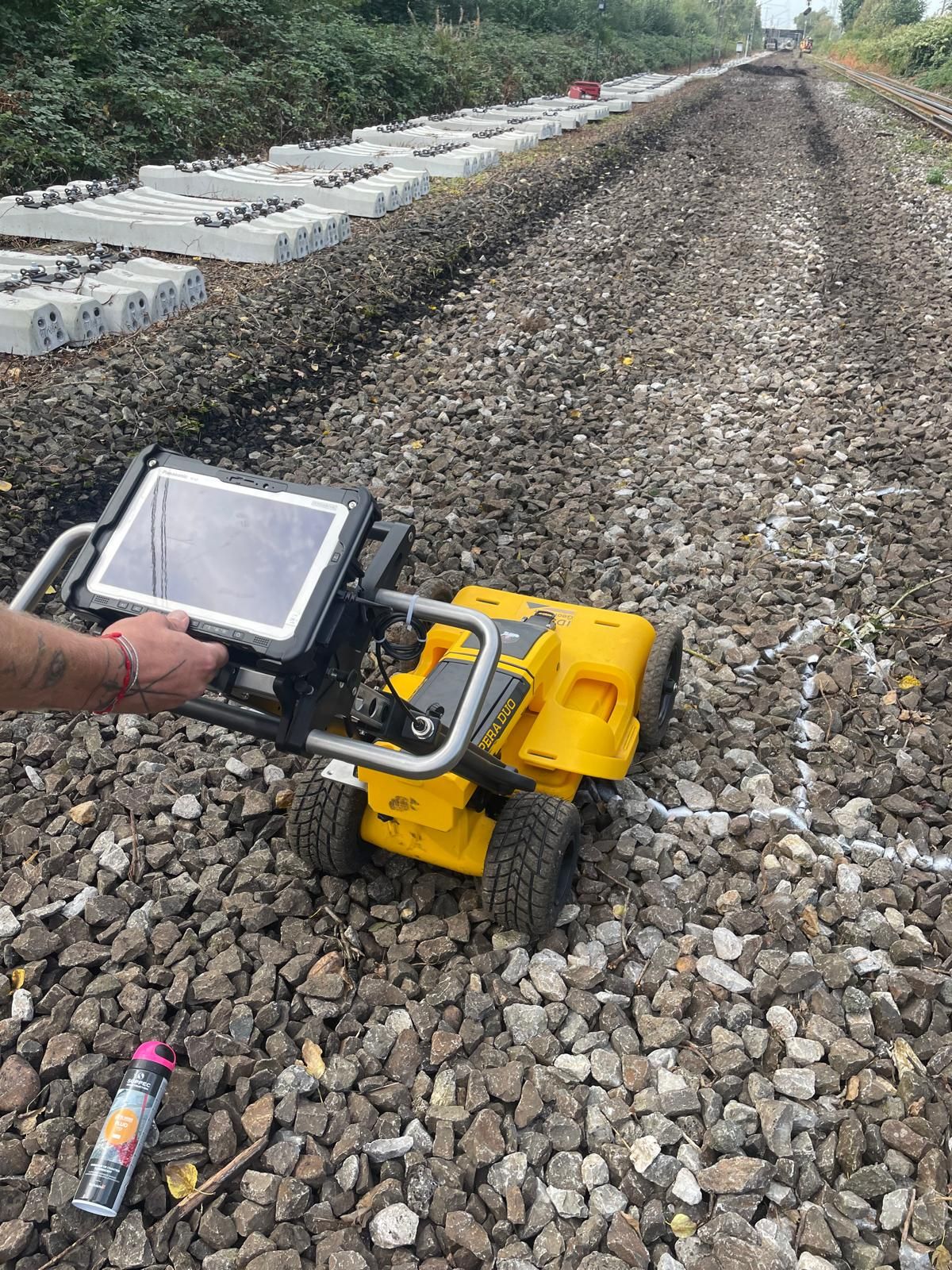
The records for railway track works between Offenburg and Niederschopfheim document 19,767 m² of surface radar surveying and seven project days. View project details.
Service areas:Surface surveys: GPR, TDEM and magnetometryMethod used in this project: Ground-penetrating radar
The records for the CargoBeamer terminal in Kaldenkirchen document 5,200 m² of GPR surveying; setting out and data interpretation are also among the services listed for the project. View project details.
Service areas:Surface surveys: GPR, TDEM and magnetometryMethod used in this project: Ground-penetrating radarSetting out and marking survey areasDocumentation and interpretation of survey data
GPR reveals structures and material contrasts in the ground. Magnetometry and TDEM measure different physical properties. The need for historical assessment, supplementary surveys or further work depends on the basis for suspicion, survey conditions and the proposed ground disturbance.
If an investigation identifies a need for further work within a defined suspect area, area clearance may follow according to the findings and clearance objective. Access, interfering objects, excavation depth and protective measures determine how it is carried out. Its location is linked to the preceding survey and documented in investigation and clearance records. The report distinguishes the surveyed area, investigated targets, the area actually cleared and zones that remain unresolved.
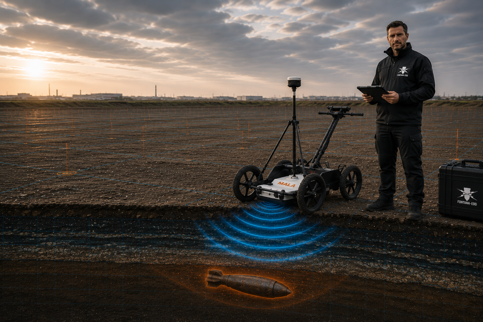
GPR records reflections and diffractions caused by contrasts in electromagnetic properties. In suitable conditions, it can map layer boundaries, utility corridors, foundations, voids, fill and individual interfering objects. The method is particularly useful when subsurface structure itself is important to assessing the suspect area.
Utilities, stones, structural remains and changes in moisture can produce similar reflections. The target, required depth, resolution and sources of interference are therefore defined before surveying. Interpretation states what the data supports and where further investigations are needed.
The conclusions depend on antenna frequency, survey grid, surface contact, moisture, conductivity, ground variability and specialist interpretation. An anomalous signal is therefore documented as a signature requiring assessment, with a spatial reference and an indication of data quality, rather than labelled as an identified object.
Compare survey methods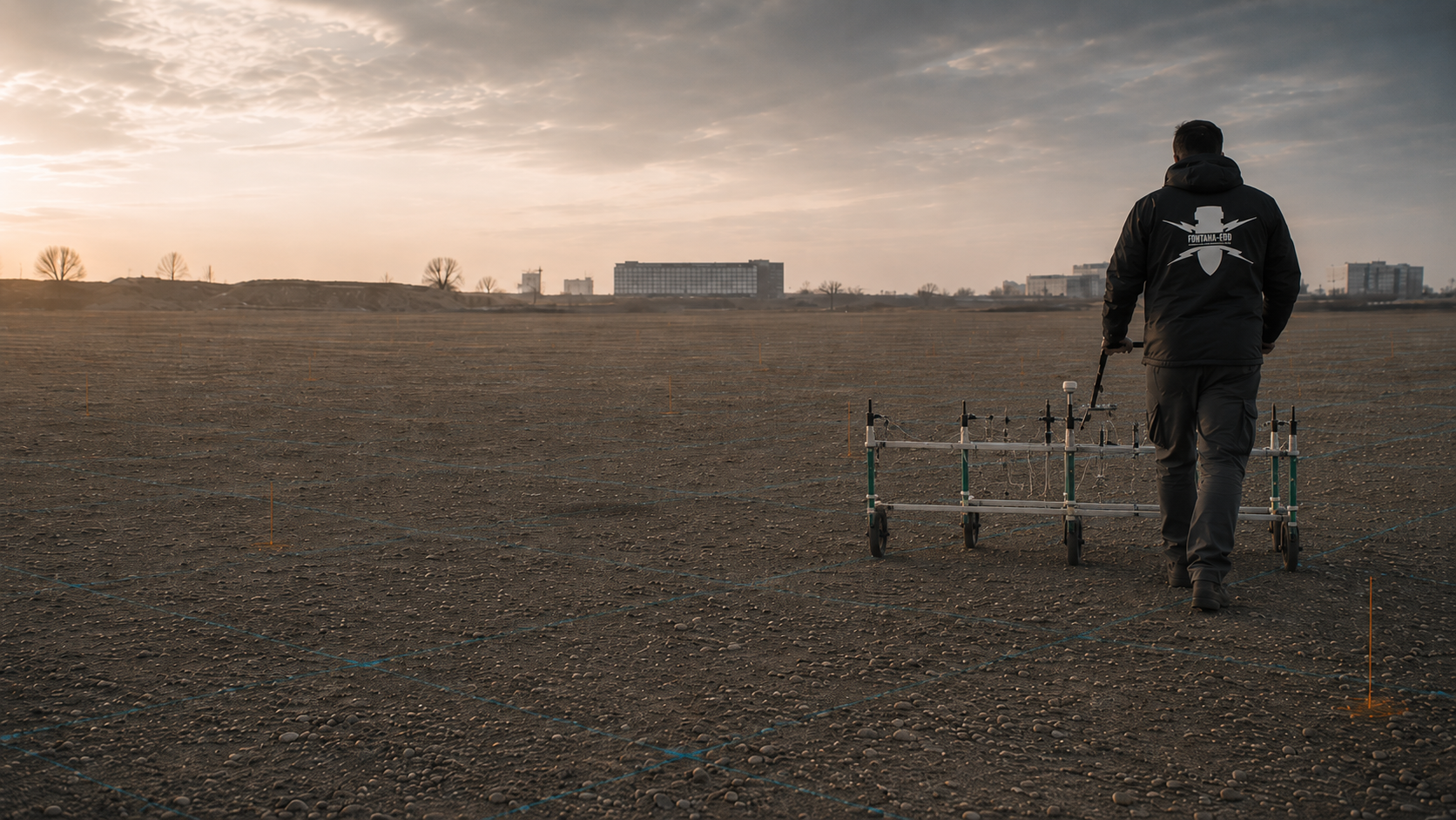
Magnetometry detects changes in the Earth’s magnetic field caused by iron-bearing or ferromagnetic objects. On open sites with little interference, it can provide a highly effective basis for area-wide explosive ordnance surveys and georeferenced anomalies for further investigation.
Rails, fences, vehicles, reinforcement, utilities and metal-rich fill can strongly mask the magnetic field. GPR can provide additional structural information in such areas, but does not automatically replace magnetometry. The combination is selected according to the target, survey environment and required conclusions.
Additional radar information can, for example, help compare the alignment of a known structure with a magnetic anomaly. Proximity alone does not establish a common cause. Both surveys must refer to the same location and be interpreted within their respective limitations. A known foundation may make a connection plausible; it does not automatically resolve every nearby anomaly.
Define the question the additional survey should answer: an unknown subsurface structure, the position of an existing installation or the interpretation of a survey target. This determines the survey extent and interpretation. Even on a combined map, it must remain clear which method supports each conclusion and where its limitations lie.
The magnetometry record includes the survey area, sensor positioning, spatial reference, anomalies and zones of magnetic interference. Combined interpretation distinguishes conclusions derived from magnetometry from those derived from radar. This allows a supplementary target investigation to address the finding that actually remains unresolved.
Understand the scope of magnetometry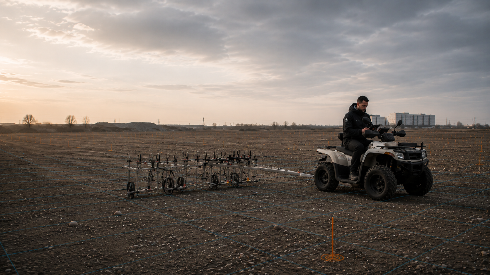
TDEM generates a time-varying electromagnetic field and measures the response of induced eddy currents. It can detect conductive objects whether or not they are strongly ferromagnetic and, with a suitable configuration, provides information about signal strength and decay over time.
TDEM is also affected by utilities, reinforcement, extensive metal structures, survey height and object geometry. GPR can supplement it when the location of structural remains, layer boundaries or non-metallic structures is needed for interpretation. Both datasets must be assessed in the same spatial reference system.
A radar finding and an electromagnetic anomaly can relate to the same area without describing the same property. A combined comparison therefore considers more than coinciding markers. It also includes the survey geometry, each method’s capabilities and known local infrastructure. Where one method is severely limited, its lack of a finding cannot simply disprove an anomalous response from the other.
Before a supplementary investigation, send the site plan, results and limitations of the initial investigation. These establish the unresolved question and the area to which the supplementary work relates. At handover, it must be clear whether the two datasets were assessed together or remain separate results.
The TDEM record states the coil configuration, survey height, time windows, spatial reference and assessed secondary signals. A comparison with GPR links the survey areas and interpretation limits of both datasets. Conductive infrastructure and areas that cannot be assessed adequately remain clearly identified as limitations.
Understand the scope of TDEM
Historical aerial photograph interpretation explains why explosive ordnance is suspected, which parts of the site may be affected and which object or event information is relevant to the technical investigation. Without a spatially justified starting point, a survey grid risks being too large, too small or misaligned with the actual ground disturbance.
For GPR, the preliminary assessment helps establish whether the targets are individual interfering objects, backfilled structures, former excavations, craters or buried infrastructure. Historical assessment does not provide a radar result, but defines the question against which the survey and interpretation are evaluated.
A former structure identified in an aerial photograph and a radar anomaly measured today represent different points in time. Comparing them can help frame a spatial question, but similar shapes alone do not justify treating them as the same feature. Construction, backfilling or other changes may have occurred since the photograph was taken. Where known, these changes inform interpretation. Where unknown, that uncertainty is taken into account.
Send the complete historical report, including every appendix. A single marker often does not show which image was interpreted, the area it covers or the applicable limitations. The subsequent survey report distinguishes historical evidence, our own measurements and the conclusions drawn from them.
Prepare the historical evidence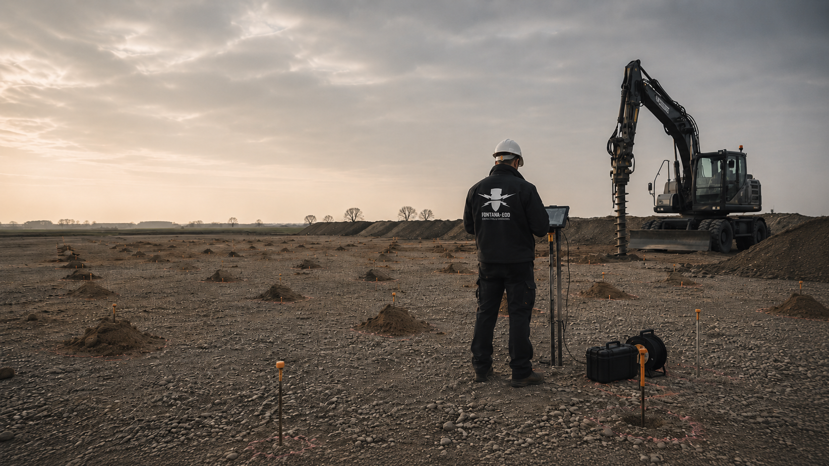
Boreholes, piles, sheet piles, anchors and other deep interventions require assessment of the actual working envelope. Even an interpretable GPR dataset covers that envelope only if the required depth, object size and ground conditions fall within the method’s technical capabilities.
If radar coverage is insufficient or depth estimation too uncertain, a separate deep-ground or borehole survey is planned. GPR can reveal layering and near-surface interference zones in preparation, but does not replace the point-specific investigation geometry required for the later intervention.
For a later point investigation, the existing radar records are reviewed alongside the current point layout. Near-surface infrastructure identified by radar may be important for preparation. However, the unresolved task at greater depth remains tied to the location and extent of that working envelope. The commission must state whether it concerns further investigation of an existing finding or assessment of a proposed intervention point for subsequent work.
Provide the point schedule and site plan at the same revision. Notify us if a point, excavation depth or structural dimensions change. Results for the old point do not automatically apply to a new location. Before work continues, the existing investigation is checked for continued relevance or a need for supplementary work.
Assess depths and borehole locations
Uninterpretable zones, dense utilities, heavy reinforcement or heterogeneous fill may prevent a complete assessment before construction. Follow-up measures must then reflect the actual construction sequence and clearly define arrangements for excavation layers, hold points, exposure and communication of findings.
A technically suitable explosive ordnance survey during construction combines technical surveying and a specialist decision before each stage of soil removal with excavation in layers under additional visual supervision. This sequence is repeated layer by layer to the planned formation level. Target investigation, by contrast, examines an anomaly already identified. Both tasks require clear coordinates, working limits, lines of instruction and spatially referenced records.
Radar results can help define a subsequent work section. The identified anomalies and unresolved zones must therefore be locatable on the construction site plan. Before follow-up work, establish which records site personnel need and how changes will be communicated. Simply forwarding a radar image is insufficient if its location, extent or assessment status is unclear.
Defined target investigation and supervision of ongoing excavation serve different purposes. The former focuses on a previously identified anomaly; the latter addresses the agreed works within the actual construction sequence. The appropriate service depends on the suspicion, working envelope and achievable control. The commission should state this relationship. Subsequent records are linked to the preceding finding so that the question investigated and the result for that area remain clear.
Understand the follow-up measureThe same radar antenna may produce very different results on neighbouring sites. What matters is the specific combination of surface, ground, suspected hazard and subsequent ground disturbance. Before surveying, the investigation objective, expected working envelope and treatment of inadequately interpretable areas must be clear.
Asphalt often permits consistent sensor movement and can suit area-wide radar profiling. However, the underlying construction — base layers, utility trenches, repairs, joints and varying moisture — produces its own reflections that must be considered during interpretation.
Before surveying, available as-built plans, construction details and proposed excavation depths are reviewed. Interpretation should show how areas differ, how anomalous signatures are assessed and where further investigation is needed.
The existing pavement and underlying ground are treated as distinct parts of the survey task. An easily traversed surface helps consistent data acquisition, but says nothing about whether the target is detectable beneath base layers, repairs or fill. Construction details and known previous interventions therefore also help assess suitability.
For phased renewal, the site plan should show whether work affects only the surface or also involves excavation of underlying layers. This changes the working envelope to be assessed. The survey area is defined so that the interpretation can later be compared with that precise intervention. Additional margins or crossings must be included explicitly in the commission. A general area figure without these boundaries can conceal different tasks.
Depending on its construction, unreinforced concrete may be surveyable. Dense reinforcement, metal plates, gratings or extensive buried installations can strongly affect signal propagation. The surface itself may then dominate the measured signal and shield or mask deeper areas.
Suitability assessment distinguishes structural inspection from explosive ordnance investigation. If the relevant ground beneath heavy reinforcement cannot be reached adequately, a different survey position or suitable supplementary method is considered. Explosive ordnance surveying during construction requires technical suitability for the actual working envelope.
Inspection of a concrete structure and investigation of the ground beneath it may use the same surface but pursue different objectives. Detecting reinforcement therefore does not prove that deeper ground has been investigated adequately. For an explosive ordnance task, a separate assessment establishes whether the survey can answer the relevant ground-related question beyond providing structural information.
Describe known structures and the proposed intervention as clearly as possible. Existing records may identify foundations, slabs, installations or previous alterations. Missing information remains an open issue in the suitability assessment. Where construction limits the conclusions, subsequent planning must show that boundary spatially. A report should not combine the inspected structure and actually interpretable ground into an undifferentiated area-wide conclusion.
GPR can offer advantages where rails, fences, utilities or foundations strongly affect magnetic surveys. This does not make the environment interference-free for GPR: above-ground reflectors, cables, structures and lateral effects can appear in the data.
Survey direction, antenna shielding, distance from known objects and control profiles are selected to help identify external reflections. Known utilities are not excluded from the assessment; they are documented as part of the spatial interpretation.
Rubble, stones, slag, varying compaction, organic material and moisture differences can produce many reflections. Such data often contains real subsurface information, but makes individual target signatures harder to distinguish.
A trial survey helps assess achievable data quality and separation of relevant signals. If specialist interpretation is inadequate, the area is not classified as free of anomalies. The data gap, its cause and the appropriate follow-up measure are recorded spatially.
A complex radar image may combine numerous real contrasts. For explosive ordnance assessment, the task is to identify the required information among these signals and judge the limits of the conclusions. The number of visible reflections therefore does not measure how completely a target has been detected. A detailed image can still make individual objects difficult to assess.
Demolition plans, information on former foundations and records of installed materials help interpretation. They do not replace surveying, but indicate which structures are plausible. An unresolved cause cannot be settled simply by assigning a colour. The open question is linked to the relevant area and considered when selecting follow-up work. This lets the client distinguish additional structural information from areas where the explosive ordnance question remains insufficiently answered.
For linear projects, survey areas, working widths, crossings and construction sections must have clear chainage references. GPR can map utility corridors, layer changes and individual anomalies along the route, provided surface and ground conditions allow sufficient data quality.
Survey lines are referenced to the route centreline, proposed trench width and required margins. For trenchless crossings or deep drilling, a separate assessment checks whether the later working envelope extends beyond the area interpretable with GPR.
The corridor actually affected by a linear project is not always the narrow centreline shown on a plan. The proposed working width, side areas and local widenings form part of the task. Otherwise, a survey may document a continuous line without covering the full space later used. Each anomaly is therefore assessed in relation to the proposed intervention.
References must also remain clear at construction-section boundaries. Differences in plan revisions, chainage or working limits must be resolved before interpretation. At handover, survey sections should be linked to construction sections. Site management can then identify the dataset relevant to the next section and any unresolved margins. A changed alignment is checked against previous survey coverage, not assumed to be covered simply because the project name is unchanged.
An area-wide radar plan can show near-surface structures and interference zones, but does not automatically establish whether a deep piling, drilling or driving envelope has been adequately investigated. The required conclusions are defined by maximum intervention depth, diameter, installation method and safety distances.
In these projects, GPR remains one element of preliminary investigation. A depth-related decision requires investigation geometry that covers the later working envelope and documents its own limitations.
Reliable GPR planning begins before the first radar profile. The commission must state the object size, depth and spatial accuracy required for the construction task. These determine antenna configuration, profile spacing, survey direction, spatial reference and quality checks.
Preparation also includes safe access, traffic and operating conditions, responsible personnel and arrangements for reporting finds. Gaps and poor-quality data are documented spatially. The depth that can actually be interpreted, considered against the proposed intervention, determines the conclusions the report can support.
The target’s size, shape, material contrast and expected position determine the required resolution. The question “Should we use GPR?” is therefore translated into a testable task: which structure must be detected, within which working envelope and with what degree of spatial certainty?
A level, continuously accessible surface supports consistent survey conditions. Rough paving, tall vegetation, steps, ballast, standing water or obstacles may change antenna clearance, interrupt survey lines and make profiles harder to reproduce.
Moisture and electrically conductive materials attenuate radar energy. Clay-rich, wet or saline ground can substantially limit investigation depth; dry, homogeneous and less conductive ground often provides better conditions. The actual site is decisive, rather than a general soil description.
Stones, rubble, varying compaction, utility trenches and structural remains generate additional reflections. A high signal density does not automatically mean good target detection. Assessment establishes whether the target signature remains spatially distinguishable within the subsurface noise.
Higher frequencies provide finer resolution, but suffer greater attenuation underground and usually reach shallower depths. Lower frequencies may penetrate deeper but depict small structures less clearly. Selection follows the target size and required depth range.
Profile spacing, point spacing and orientation must suit the expected object size. Excessive spacing may miss narrow or unfavourably oriented structures. Intersecting control profiles and a traceable spatial reference help check whether anomalies are reproducible.
Radar profiles, anomalies, obstacles and data gaps are recorded in an agreed spatial reference system. GNSS, total-station surveying or local reference points are selected to suit the site. Subsequent relocation must use the same spatial basis.
Where survey conditions are unknown or vary considerably, a trial survey can establish achievable data quality. Control profiles, equipment checks, documented settings and early data review help prevent an unsuitable configuration being continued across the entire site.
The radar image is accompanied by a report explaining the survey area, data processing and interpretation. It records which areas were investigated, what the data reveals and which questions remain unresolved.
The project objective, proposed ground disturbance, basis for suspicion, expected targets and required depth range are documented. Historical records, authority correspondence, as-built plans and previous surveys inform assessment with their dates and spatial references.
The site plan, area boundaries, profiles, survey direction, spacing, excluded areas and obstacles must be clearly identifiable. Differences between the planned area and the area actually traversed are documented so that subsequent planning does not overlook them.
At handover, planned and actually surveyed areas are compared. The outer boundary is not the only consideration. Excluded islands, interrupted profiles, obstacles and inaccessible margins may lie within an area whose perimeter was traversed. The coverage record must show these differences. A closed property boundary on an overview plan alone does not describe survey coverage.
A subsequent contractor needing a specific working area can compare these records with its commission. Removing obstacles or making additional areas accessible creates a new available survey area. Whether supplementary surveying is needed there depends on the unresolved task. Documentation distinguishes areas already surveyed from those intended for later work.
The survey system, antenna configuration, time window, recording parameters, positioning method and relevant equipment checks are recorded. These details support specialist assessment of resolution, expected depth range and comparability between survey sections.
Raw data is retained as the starting point for interpretation. Processing and filtering are described transparently, showing how recorded traces became radargrams, time slices, depth sections or other visualisations.
Anomalies are recorded with their profile, position, travel-time or depth reference, signature type and assessment status. Known utilities, structural remains and other plausible causes are considered. Classification remains subject to data quality and the available comparison information.
Consistent identifiers help link survey findings, assessment and subsequent work. A point identifier should be traceable in the plan, schedule and any supplementary target investigation. Merging, reassessing or moving points must remain visible. Otherwise, follow-up work may address a different location from the one covered by the original interpretation.
Assessment status also matters when communicating findings. A detected structure, a plausible explanation and a suspect point still requiring investigation are different statements. The report should therefore explain its terminology. Later exposure or investigation of a point adds evidence to the radar interpretation. That follow-up result must not be presented retrospectively as something already established by the original radar image alone.
The report identifies areas with shallow penetration, dense reflections, inadequate access or uncertain depth conversion. This informs a specific next step, such as supplementary magnetometry or TDEM, target investigation, a deep-ground survey, excavation supervision or use of the result within the documented area.
A spatially marked limitation needs a clear explanation. Three causes must be distinguished: the area was not surveyed; radar energy was attenuated too strongly; or numerous reflections prevented adequate separation of the target signal. Different supplementary tasks may suit each cause. The next commission should address the stated gap specifically.
Exposure or clearance generates its own work and findings records. Where these services form part of the subsequent project, their records are linked to the preceding survey documentation. A clearance record thus documents work actually carried out; a previous radar map does not replace it. At handover, the client and site management should be able to see which stage is complete and which decision remains before the next ground intervention.
The report must trace conclusions back to the acquired data. Profile routes, processing steps, control surveys and the basis of depth information are therefore documented.
If surveying is followed by exposure, area clearance or recovery, the resulting findings and clearance records are linked to the preceding survey documentation. The record then identifies the stage actually completed and its limitations. Survey documentation alone does not claim that these follow-up works have already been completed.
Before surveying, the basis for suspicion, construction site, proposed intervention and target are linked clearly. This makes it possible to understand why an area was investigated and which question the dataset is intended to answer.
Profile routes, coordinates, area boundaries and obstacles are recorded consistently. Position discrepancies and survey gaps remain visible so that subsequent relocation does not rely on an inaccurate picture of coverage.
Key processing steps are recorded so that the creation of the visualisations can be traced. Raw data, processed data and interpretation remain distinguishable.
Control profiles, repeat surveys, visual checks and plausibility comparisons show whether anomalies are reproducible and whether survey quality varies significantly across the area.
Depth information is based on radar-wave travel time and an assumed or calibrated propagation velocity. The basis used and remaining uncertainties are stated in the assessment.
The report, maps, data summaries and follow-up decision are brought together so that designers and site management can clearly locate the investigated area, findings and unresolved issues.
We first clarify the survey task and the method’s suitability. Survey planning, radar profile acquisition and interpretation follow. Required records, control surveys and reporting formats are agreed before work begins.
The construction site, route, structure, intervention depth, programme and required decision are described clearly.
The basis for suspicion, site plan, utilities, ground construction, access and known interference are considered together. For explosive ordnance questions, we also check whether the historical evidence adequately covers the area concerned. If questions remain, suitable aerial photographs and other historical sources are researched and assessed spatially. The result is linked to today’s intervention areas and considered in further investigation planning.
Target size, soil moisture, electrical conductivity, ground variability and required depth are assessed against GPR suitability.
Antenna configuration, profile grid, survey direction, positioning method, control profiles and subareas are planned.
Radar profiles, obstacles, survey gaps and changes in survey conditions are recorded spatially.
Raw data undergoes quality-controlled processing into radargrams, sections or area-wide visualisations.
Anomalies are compared with ground conditions, existing records, interference sources and the suspected hazard, then classified spatially.
The report, plans, data quality, depth reference and necessary follow-up measures are assembled for the project file.
GPR data is indirect. It records electromagnetic responses from the ground and requires interpretation. Reliable interpretation distinguishes recorded signals, processing steps, spatial visualisation and specialist conclusions.
Each trace shows received radar energy over travel time. Recording many traces along a profile produces a radargram: a vertical section through the ground. Point-like or spatially limited objects often appear as characteristic diffraction patterns rather than simple object outlines. Their shape is affected by survey geometry and wave propagation.
Area-wide assessment requires multiple accurately positioned profiles. The data can be used to derive horizontal travel-time or depth intervals, spatial signature patterns and recurring structures. The quality of that visualisation depends on whether profile spacing, positioning and processing suit the size of the target structure.
Using a radargram and a spatial survey-data view, the Plattling example explains which signal features are visible and what additional information specialist assessment requires. The description distinguishes survey parameters, anomalies and subsequent clearance and verification steps.
A radargram is a profile image composed of many individual traces. Utilities, stones, voids, object edges and other contrasts can generate curved or banded signatures. Similar shapes may have different causes; interpretation therefore requires site plans, parallel profiles and knowledge of the survey environment.
A radargram is read along a survey line. Its horizontal direction represents antenna movement; the other initially represents the received signal’s travel time. A curved signature therefore does not necessarily indicate a curved object. The same spatially limited reflector may be recorded from multiple antenna positions, with the signal path changing accordingly. Inferring the shape of a bomb, utility or other object directly from that pattern skips this relationship between acquisition and visualisation.
Interpretation considers whether an anomaly recurs in neighbouring profiles and how its position changes. A structure traceable across several profiles can be described differently from a single brief signal. Its cause nevertheless remains a specialist interpretation initially. A plausible utility structure is checked against existing plans and site conditions. For a suspect point, the report must explain why the available information requires further investigation.
The visualisation should therefore be supplied with distance and travel-time scales, a profile identifier and a spatial reference. An isolated crop may show a distinctive shape but can only be transferred to a construction plan to a limited extent. When consulting the specialist contractor, the profile number and corresponding position on the site plan are more useful than a standalone screenshot. Discussion then remains tied to an unambiguously identified survey finding.
A structure’s size relative to the wavelength also affects its appearance. If an object is too small for the wavelength used, its outer shape cannot be resolved directly, although it may still produce a diffraction pattern. The width of that pattern in the radargram must therefore not simply be transferred to a plan as the object’s width. Interpretation must distinguish features actually supported by the survey from those requiring further investigation.
This distinction is useful in project discussions: a professionally described anomaly may be located precisely enough for further investigation even though its cause and dimensions remain unresolved. The report then states the measurable finding and the open question. That supports a targeted next commission without treating the graphic signature as complete object identification.
The instrument initially measures travel time, not depth directly. Depth conversion uses an assumed propagation velocity or one calibrated from survey data. Moisture changes and different materials affect that velocity. Depths are therefore reported with their assessment basis and appropriate precision.
Between transmission and reception, the signal travels through the ground and back to the antenna. Converting this time to depth requires an assumed or determined propagation velocity. That basis forms part of the result. If material or moisture changes along a profile, a single velocity may not describe conditions equally well everywhere. Signatures at the same height in an image therefore need not occur at the same actual depth throughout the site.
Construction planners should be able to see whether a depth derives from calibration, a model assumption or other available information. Remaining uncertainty must also suit the intended decision. Approximate placement of an extensive structure may help prepare further surveys. Assessing a narrow working envelope for a deep intervention, however, requires an investigation that supports that precise task. A number on a depth axis alone does not establish this.
Later comparisons between datasets also require a common reference. If ground level, elevation or plan revision changes, the reference for each depth must be clarified. Interpretation should explain this clearly enough for a subsequent design consultant to use it. Otherwise, two technically correct values may still refer to different levels. Complete handover therefore includes both the values and the basis of their spatial reference.
Fine structures require sufficiently high frequency and close survey spacing, often at the expense of achievable depth. Lower frequency may suit greater depths, but depicts small objects more coarsely. This trade-off is resolved before surveying according to the expected target.
Resolution describes how finely neighbouring structures can be distinguished in the data. Investigation depth addresses a different question: how deep do conditions permit information that can be interpreted for the task? Survey design must consider both. A configuration that detects a large structure may be inadequate for a much smaller target. Conversely, high near-surface detail may not support conclusions about a deeper working envelope.
An enquiry therefore needs more than a general depth figure. Describe the structure or object relevant to your project and how deep the works will extend. State any uncertainty if these details remain open. The specialist contractor can then explain which information is needed to select the antenna and grid. A quotation should identify its technical assumptions about the survey objective so that configurations can be compared meaningfully.
Where ground conditions vary, the quality actually achieved must also be assessed. A chosen setting does not necessarily support the same conclusions in every subarea. Observable changes during acquisition and early data review are therefore considered. The report should locate restricted areas so supplementary investigation can address the unresolved question, rather than treating a general equipment description as proof of coverage for the whole site.
Area-wide visualisations combine signal strengths within selected travel-time or depth intervals. They help identify linear, extensive and point-like patterns. Without reference to the underlying profiles, however, they must not be treated as independent object maps.
A time slice maps a selected travel-time interval across an area. Its patterns may show whether an anomaly continues across profiles, follows a linear route or divides an area into different structural zones. It is a visualisation derived from survey data. Pattern clarity also depends on the survey grid, processing and selected time interval. A strong colour alone therefore represents neither a specific material nor a particular hazard.
A depth section additionally depends on the basis used for depth conversion. Without reading that basis in the accompanying report, a graphic layer can appear more precise than the data allows. Specialist assessment therefore includes the underlying profiles and processing description. A designer should be able to understand whether a depicted area represents a measured structure, an interpreted extent or an area needing further investigation.
A clear legend helps site management use the result. Working limits, survey gaps, known utilities, assessed anomalies and unresolved causes have different functions. Distinguishing them graphically allows comparison with the proposed working area. The plan can then support discussion without turning every coloured zone directly into a construction decision. Queries refer to the identified visualisation and its interpretation revision.
Corrections, gain, filtering, background processing and spatial reconstruction can clarify relevant signatures. If applied unsuitably, they can also alter structures. Processing and interpretation are therefore checked against raw data and control profiles.
Recorded data and the visualisations prepared for a report are not the same. Processing helps make signal components readable and investigate spatial relationships, but also affects which features stand out or recede. Raw data, processed data and interpretation must therefore remain distinguishable. A particularly high-contrast graphic does not itself prove better target detection.
Plausibility checking asks whether an anomaly is supported by the original data, recurs in neighbouring profiles and fits known site conditions. A suspected structure is not confirmed simply because a particular display makes it prominent. Obstacles, interrupted profiles or changes in antenna movement can also affect interpretation. Field records and survey data are therefore assessed together.
Clients should clarify which data and explanations will actually be handed over. Finished images alone provide a different scope from raw data with documented processing steps. Agree the required data scope before commissioning, particularly if another consultant will continue the investigation. The report should also identify the data and plan revisions supporting its conclusions, keeping later additions and queries tied to the correct revision.
Spatial reconstruction also changes how survey signals are displayed. It should assist interpretation, but does not create additional survey coverage where no suitable data was acquired. A site plan must therefore distinguish information from actually recorded profiles from the visualisation derived from them. Graphic continuity and investigated area remain separate.
An anomaly is assessed by position, depth, shape, repeatability and known interference sources. If its cause remains unresolved and it affects the proposed working envelope, follow-up may include supplementary surveying, target investigation, exposure or measures during construction, depending on the project.
Three questions are considered separately for the next decision: What does the data show? What cause is plausible from the available information? What does the finding mean for the proposed intervention? This sequence prevents a strong signal becoming a supposedly certain object identification. It also prevents a potentially explainable anomaly being treated as resolved without adequate investigation.
If a signature follows a known utility, its position may support an explanation. The planned alignment, survey finding and site information must agree. An additional anomaly beside that structure may present a separate question. A signal outside the proposed working area remains a documented finding, but has a different spatial relationship to the immediate works from a signal within the excavation. Assessment distinguishes these situations.
The appropriate follow-up service depends on the unresolved question. A repeat survey can check reproducibility; another method can add different physical information. Target investigation instead involves the prepared, closer examination of an identified point. A deep working envelope may require its own survey geometry. The report should explain which question the proposed next step is intended to answer, helping the client understand why further work is needed and where its scope begins.
In the Plattling project, an IDS Opera Duo acquired GPR data across approximately 1,432 m². The completion report specifies 250 and 700 MHz, 0.50 m profile spacing and 0.04 m measurement-point spacing. The 294 recorded anomalies were survey anomalies; overlapping signals limited object identification. Subsequent work comprised clearance and final verification.
The four original radargrams and four 3D survey-data views show the difference between profile images and spatial visualisations. The project report with survey parameters and limitations provides the technical context. The related Plattling reference and the Lower Bavaria region provide the local project context.
Open the Plattling report extract with a sanitised site plan (PDF, 10 pages)
The working limits of the subsequent clearance phases can be traced in the sanitised original plan separately from the GPR survey parameters.
GPR, magnetometry and TDEM measure different physical properties. Historical investigation, deep-ground surveying and excavation supervision address other project questions. Reliable selection assesses each service’s technical contribution, suitable working envelope and principal limitation separately.
Technical contribution: Structural information, paved areas, utility and structural context, and spatial reflection patterns.
Principal limitation: Strong attenuation, heterogeneous fill and ambiguous signatures; no definitive object identification.
Technical contribution: Sensitive detection of ferromagnetic anomalies on suitable sites with little interference.
Principal limitation: Interference from rails, fences, reinforcement, vehicles, utilities and metal-rich fill.
Technical contribution: Active detection of conductive metal objects, complementing magnetometry for suitable targets.
Principal limitation: Affected by extensive conductive structures, utilities, reinforcement, survey height and object geometry.
Technical contribution: Establishes the basis for suspicion, defines subareas and identifies targets and events relevant to technical investigation.
Principal limitation: Does not directly establish which objects are actually present today.
Technical contribution: Investigation of defined point and depth envelopes for piles, boreholes, sheet piles and other deep interventions.
Principal limitation: Applies only to the defined investigation geometry and does not replace area-wide assessment outside it.
Technical contribution: Where technically suitable, remaining working envelopes are surveyed and assessed before each stage of soil removal. Following the specialist decision, excavation proceeds in layers under additional visual supervision. This sequence continues to the proposed formation level.
Principal limitation: Applies to the supervised work sections and requires coordinated site organisation.
A geotechnical consultant focuses on a different working envelope from a utility-trench designer or a contractor demolishing old foundations. State how the radar profiles will be used: for example, locating an anomaly, comparing it with as-built plans or preparing further surveys. The data scope is tailored to that question. Specialist explosive ordnance assessment remains separate from geotechnical, structural and utility-related investigations.
Understand explosive ordnance assessment by construction taskA further survey should close a specific information gap. The existing radar result and proposed working envelope are therefore considered together.
A radar plan does not explain the historical reason for investigating explosive ordnance. Where this basis is missing, historical assessment helps define the technical question and spatial context.
If the investigation primarily targets ferromagnetic or conductive metal objects, the strengths and limitations of magnetometry and TDEM are compared with radar conditions. Combining methods must add technical value for the task.
For a pile, borehole or shoring alignment, the entire affected working envelope matters. If it lies beyond the adequately interpretable radar range, a suitable deep-ground or borehole survey is considered.
Before surveying, responsibilities are established for providing records and site access, planning the investigation, interpreting the data and incorporating the result into construction.
Defines the project, provides existing records and identifies the decision needed for design, procurement or construction. Ensures that the investigation area and subsequent intervention correspond spatially.
Define the area, route, borehole locations, intervention depth, existing utilities and technical constraints. Incorporate the survey result into construction design, specifications and other specialist reports.
Assesses method suitability, develops the survey design, acquires and interprets data, and describes the investigated area, limitations and necessary follow-up measures.
Arrange access and suitable site conditions, coordinate closures and working windows, and account for documented data gaps, anomalies and hold points in the actual construction sequence.
Plans surveying and quality assurance, oversees data acquisition and takes responsibility for specialist interpretation. Geophysical interpretation and explosive ordnance assessment are coordinated.
Names and responsibilities vary by region. Depending on the project location and findings, the competent authorities handle hazard response, finds and decisions on further measures.
The responsibilities of KBD, KMBD or KRD and local public-order authorities vary by project location. Building control may also be involved. Existing correspondence is forwarded with its date and spatial reference; specific decision-making and reporting arrangements are clarified locally.
GPR surveying alone is distinct from subsequent activities such as exposure, identification, recovery or handling an actual find. Qualifications, work organisation and documentation therefore relate to the specific service scope and project phase.
For relevant commercial activities involving explosive substances, the licensing and responsibility framework of the German Explosives Act (SprengG) applies: section 7 concerns the commercial licence, and section 20 the certificate of competence for responsible persons. Geophysical surveys to search for unexploded ammunition must also be assessed under explosives legislation; searching is expressly covered by section 1b(1), no. 3(d) SprengG. The specific survey purpose, subsequent work and assigned responsibilities determine the requirements.
DGUV Information 201-027 supports specialist contractors and design and engineering consultants with risk assessment and protective measures for explosive ordnance clearance. DGUV Rule 113-003 particularly concerns dismantling or destroying explosive articles and disposing of found ammunition. GPR surveys must also account for general occupational safety requirements, site traffic, utilities, terrain, access and safe operation of the survey system.
The German federal construction guidelines for explosive ordnance clearance (BFR KMR) provide technical foundations and specifications for geophysical investigations, including suitability assessment, personnel, quality assurance, survey execution and documentation. Their direct scope of application must be observed; they also provide a transparent framework for planning and evaluating geophysical services.
The First Ordinance to the German Explosives Act (1. SprengV) includes requirements for specialist competence and state-recognised courses. For GPR services, the necessary qualifications depend on the specific survey purpose and activities actually commissioned.
The project question, area, depth, target, survey conditions and required deliverables are clearly defined before work begins.
Survey planning, data acquisition and interpretation require geophysical expertise and an appropriate explosive ordnance assessment.
Site access, traffic, utilities, obstacles, equipment handling, reporting of finds and potential follow-up work are considered during preparation.
Raw data, processing, survey geometry, quality checks, anomalies, limitations and conclusions remain linked transparently.
The specification, investigation objective, area and depth references, data formats, quality requirements and acceptance criteria are defined clearly enough for meaningful technical comparison of quotations.
Survey areas, settings, profile routes, changes, interference and inaccessible areas are documented continuously. Significant deviations are agreed with project management.
Stop work immediately. Do not touch or move the object. Leave the danger area, warn others without putting yourself at risk and notify the police immediately — in Germany, call 110. Also inform site management and follow the emergency services’ instructions.
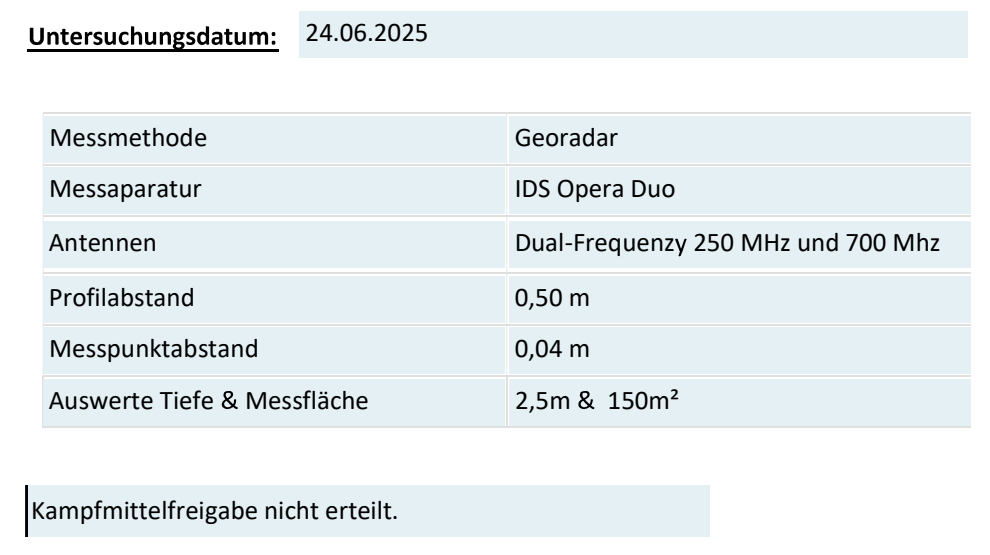
For the B37/ESTW Hochspeyer project, FONTANA-EOD surveyed an area using GPR on 24 June 2025. The survey report documents 150 square metres and an interpretation depth of 2.5 metres. These figures describe the investigated project area; they are not a general statement of GPR range.
The precise nature of these anomalies had not been verified when the report was issued. No explosive ordnance clearance was therefore granted. The example illustrates an important limitation: geophysical surveys can reveal a need for further investigation without identifying an object or authorising the next stage of work.
Result: no clearance. This report does not establish any subsequent resolution or clearance.
Explosive ordnance assessment services · Explosive ordnance assessment in Rhineland-Palatinate · Further reference information
Open survey parameters and result as a PDF
Implication for subsequent planning: In this case, the survey alone was insufficient to clear the investigated area. The anomalies still required investigation before further work. This report does not demonstrate any subsequent resolution or clearance.
Radar profiles are linked to their location, survey grid and specialist assessment. Depth, resolution and known ground conditions determine how signatures can be interpreted and used in the next stage of work.
Survey traces are assigned to the actual site, allowing anomalies, obstacles and data gaps to inform design and subsequent relocation.
Interpret radar profiles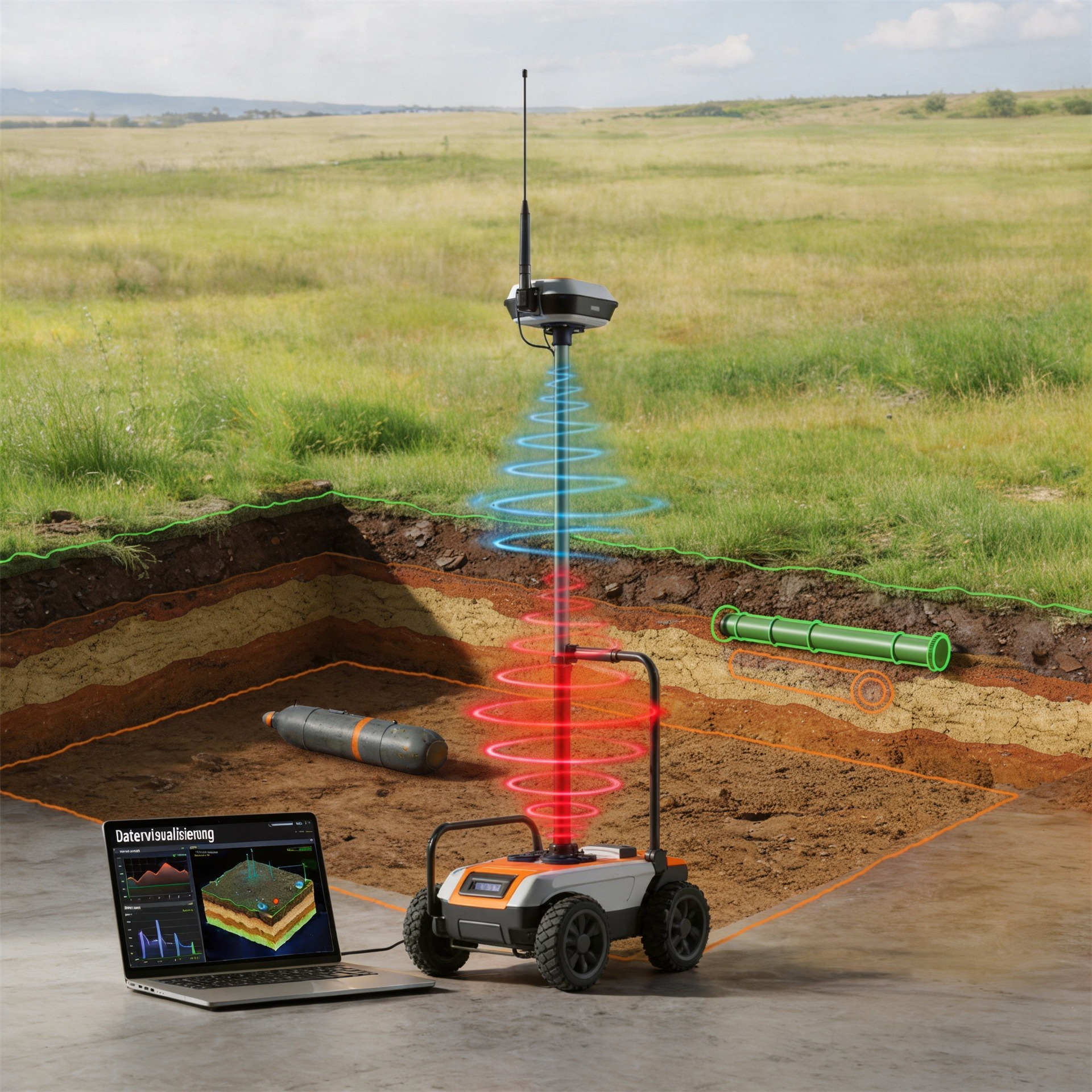
Reflections occur at contrasts in electromagnetic properties. The position and shape of a signature depend on the object, layer boundary and survey geometry.
Explore measurement principles and method selection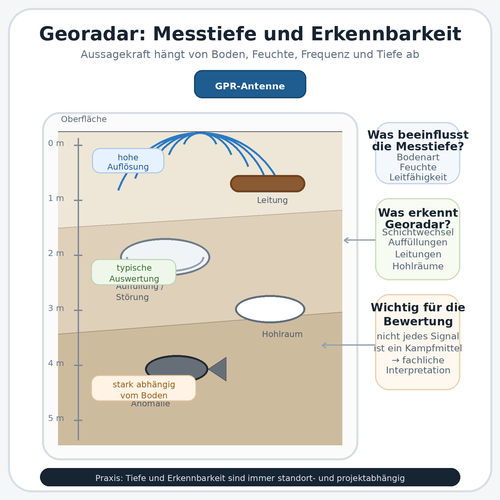
Antenna frequency, soil conductivity, moisture, object size and survey spacing affect whether a structure remains detectable within the required working envelope.
Clarify depth and detectability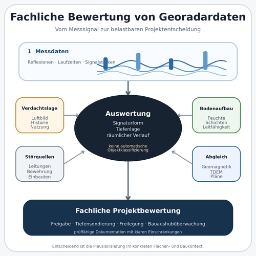
Signatures are not interpreted in isolation. Parallel profiles, as-built plans, ground information and the basis for suspicion inform reliable assessment.
Assess data quality and limitations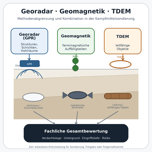
GPR provides structural information, magnetometry responds to ferromagnetic objects, and TDEM to conductive objects. Combined assessment requires matching spatial references.
Compare supplementary survey methods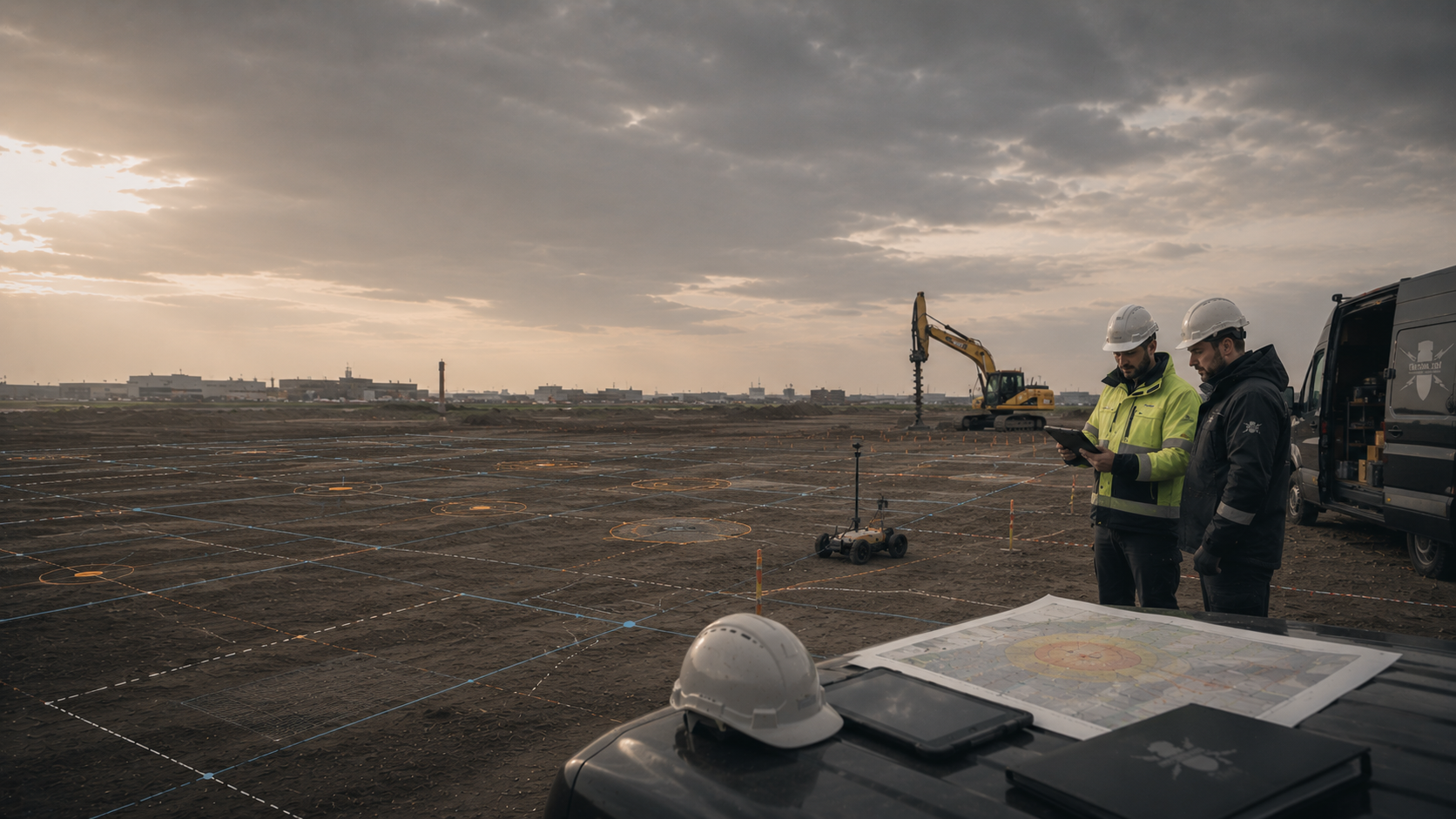
The method is combined with the suspected hazard, working envelope, supplementary methods and subsequent documentation to form an investigation design.
Identify suitable follow-up services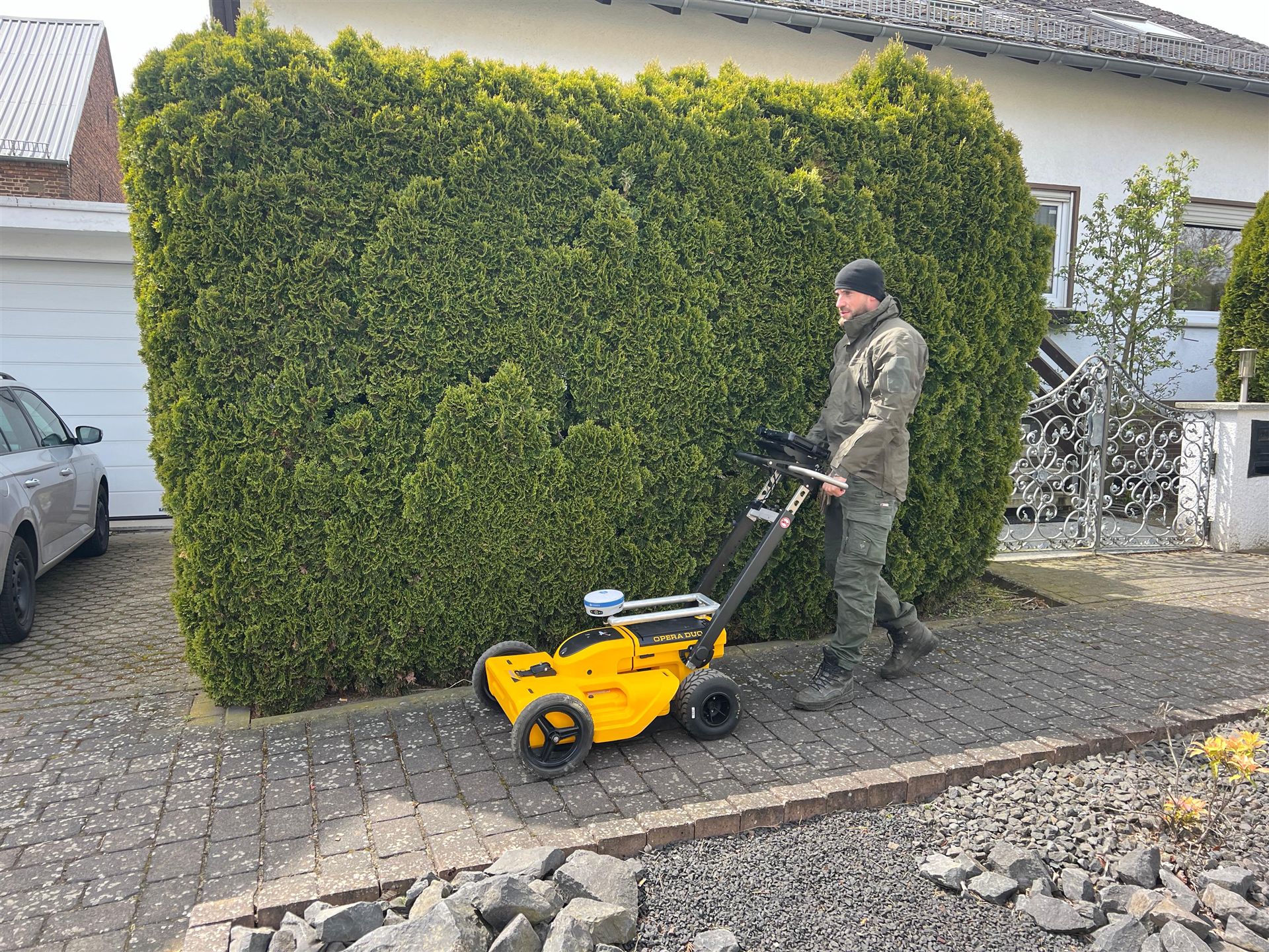
Documented survey limitations and the proposed working envelope determine follow-up services. For supplementary surveying, a deep intervention or closer target investigation, existing results are compared with the unresolved task.
Select magnetometry, TDEM and GPR according to the area, target and interference conditions.
Compare surface survey methodsAssess ferromagnetic anomalies and sources of magnetic interference.
Magnetometry: applications and limitationsAssess conductive metal objects and time-dependent electromagnetic responses.
TDEM: applications and limitationsInvestigate borehole locations, piles, sheet piles and other deep working envelopes separately.
Survey at depthClarify the basis for suspicion, subareas and target context before technical surveying.
Assess the suspected hazardIntegrate areas that cannot be resolved in advance into the actual excavation sequence and site organisation.
Plan specialist excavation supervision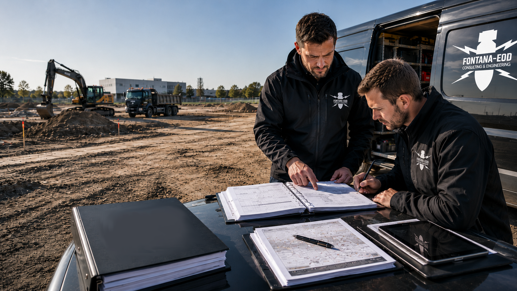
Organise survey data, interpretation, limitations and the follow-up decision for the project file.
Clarify documentation requirements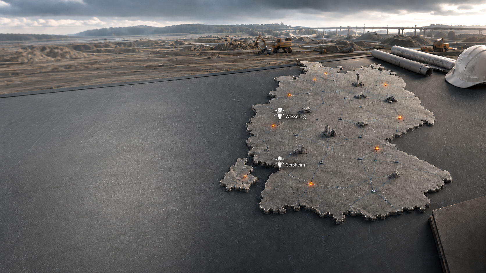
Identify the project location, regional interfaces and operating area for the enquiry.
Regional contacts and proceduresIdentify the role of historical assessment, surveying, clearance, recovery, construction supervision and documentation at the project’s current stage.
View all servicesAssess GPR against the construction task, infrastructure type, operating environment and project phase.
View applicationsTo plan radar profiles, we need the proposed survey area, access and known obstacles as well as the address. Include existing local correspondence and previous investigations with their area references. A similarly named development or neighbouring investigation does not replace this spatial reference.
A spatially detectable signature can have several causes. A clearly visible hyperbola therefore does not, by itself, answer the explosive ordnance question. Interpretation, comparison data and, where necessary, further investigation remain decisive.
Understand assessment and supporting recordsBefore tendering, the selected survey method should match the required conclusions. A commission based solely on square metres leaves the required profile grid, spatial reference and interpretation for the proposed intervention undefined.
Clarify the survey task before commissioningFor an uninterpretable subarea, the cause and location are documented. These determine which additional service can answer the unresolved question. Another instrument alone will not necessarily remove the limitation.
Select a suitable follow-up serviceA large surveyed area does not prove adequate target detection. Where conditions are uncertain, first establish whether the chosen configuration can support the required conclusions under the site’s ground and interference conditions.
Alongside radar traces, interpretation requires survey records: profile routes, positioning, obstacles and changes to the site. Handing over these details together supports transparent assessment of anomalies and survey gaps.
The project file must distinguish interpretable results from unresolved areas. When plans later change, the radar image is not simply reused; the new working envelope is checked against the documented conclusions.
Technical information
The brochure explains GPR principles and uses survey images to show how results are interpreted. It also explains the effects of ground conditions and the limits of investigation.
GPR records electromagnetic reflections and diffractions at layer boundaries, objects and other changes in the ground. An anomalous signature may relate to an object relevant to explosive ordnance assessment, but may also arise from utilities, stones, structural remains, voids, fill or moisture changes. Data must therefore be compared with the basis for suspicion, site plans, parallel profiles and other survey methods. A radargram alone does not provide definitive identification.
There is no credible universally applicable depth. Investigation depth and data quality depend on antenna frequency, soil moisture, electrical conductivity, clay and salt content, ground variability, object size, surface and interference. What matters is not whether any signal is visible at a particular depth, but whether the expected target can be assessed within the project’s relevant working envelope with sufficient resolution and transparently stated uncertainty.
Asphalt and even paving may provide favourable conditions for controlled sensor movement. For concrete, suitability depends strongly on construction, thickness and reinforcement. Dense steel reinforcement, metal plates, gratings or buried installations can limit signal propagation and visibility at depth. The surface, structural construction, utilities and required depth are therefore assessed before area-wide surveying; a trial survey may help where conditions are uncertain.
GPR is particularly relevant when structural information about layers, fill, utilities, voids or structural remains is required, or when rails, reinforcement and other ferromagnetic structures strongly mask magnetic measurements. Magnetometry, however, is often highly sensitive to ferromagnetic targets on suitable sites. In many projects the two methods answer different questions and are used together rather than as competing alternatives.
Useful information includes the project address, site plan, land parcel, construction-site or route boundaries, proposed intervention depth, construction phase, surface construction, utility and as-built plans, geotechnical information, existing aerial photograph assessments, previous survey reports and the decision required. Linear projects should show chainage and working width; individual interventions should show coordinates and target depths.
Clarify suitability before tendering and ground disturbance wherever possible. After reviewing records and the site, survey design, acquisition, specialist interpretation and handover are tailored to the next project decision.
Include existing authority information and conditions with dates, complete appendices and their spatial scope. The project location determines the competent bodies and local coordination arrangements.
Raw data undergoes quality-controlled processing and is presented as radargrams, area-wide travel-time or depth intervals and georeferenced anomalies. The report describes the system, antenna configuration, profile grid, spatial reference, processing, survey conditions, known interference and depth model. It records how signatures were assessed, which areas could not be interpreted and what uncertainty remains. It then derives the next steps for design or construction.
Key factors are area and geometry, profile grid, access, surface, number of survey sections, required antenna configuration, positioning method, interference, data quality, interpretation scope and documentation. Large open areas may need different field effort yet generate substantial data; small urban sites can demand considerable work because of obstacles and complex interpretation. A reliable estimate therefore requires clearly defined location and scope.
Areas with strong attenuation, dense reflections, heavy reinforcement, inadequate access or uncertain depth conversion are located and technically explained. Depending on the project question, follow-up may include magnetometry, TDEM, another antenna configuration, trial profiles, deep-ground or borehole surveys, target investigation, exposure or excavation supervision. Poor data quality is not a finding of no anomalies. The report must identify unresolved questions and how they can be investigated further.
If a suspicious object is found, stop work. Do not touch or move it. Leave the immediate area, warn others without putting yourself at risk and notify the police — in Germany, call 110; outside Germany, use the local emergency reporting arrangements. KBD or the competent local authorities take responsibility for further hazard response according to the actual find.
A manageable set of records is often enough for initial assessment. What matters is a clear description of the area, ground intervention and decision required. Missing information can then be added selectively.
We need the project address, site plan, land parcel, survey limits and details of asphalt, paving, concrete, ballast, vegetation or indoor areas. Obstacles, traffic, operations, level changes and inaccessible areas affect survey execution and effort.
For routes, length, working width, chainage and construction sections are useful. At existing facilities, known foundations, rails, fences, machinery and other potential reflectors should be located spatially.
Also mark which parts of the site will actually be accessible at the proposed survey time. Parked equipment, continuing operations or a construction section available only later can affect the sequence. Describe these conditions as currently known. Necessary and permissible preparation is agreed in relation to the suspected hazard and investigation commission; making an enquiry does not require independently undertaking groundworks beforehand.
For multiple construction sections, clear priorities help. Describe which section needs a decision first and which areas should follow. The boundaries of the proposed works should remain visible on the plan. This helps agree whether surveying and handover should be prepared together or in phases. Later changes can then be assigned to a specific part of the commission, rather than assuming an unchanged technical task from a general programme change.
Ground profiles, fill, groundwater, contamination information, utility plans and previous excavations support suitability assessment. Existing aerial photograph assessments, authority correspondence and previous explosive ordnance reports are compared with the proposed survey area.
Incomplete as-built plans are relevant too. They show which utility or structural information requires particular care in verification and documentation during surveying.
Forward existing records with their appendices wherever possible. An older report may cover another area or intervention despite naming the same project address. Assessment therefore requires the commission, survey area, result and limitations together. Identify missing components in the enquiry so that the conclusions safely usable from available records can first be established.
The revision of utility and as-built plans also matters. A plan may show known installations without every later alteration. Describe changes you know about and details that remain uncertain. This helps compare the later survey with site conditions. Such information is not treated as an already confirmed survey finding. Specialist assessment distinguishes existing plan information, site observations and actually interpreted radar data.
Describe excavation, utility trenching, milling, foundations, drilling, demolition or other intervention with its maximum depth and working width. Where known, provide expected object size, material type and the spatial basis for suspicion.
The intended use is equally important: method selection, tendering, an anomaly plan, utility and structural comparison, preparation of further surveys, or documentation for site management and the project file.
Finally, identify who will use the result next. A designer may need a basis for further design, while site management needs the documented position for a particular upcoming work section. This affects how the area, report and unresolved issues are assembled at handover. The technical conclusions themselves remain tied to the scope actually investigated.
You can also send several design options. Mark the affected area and proposed intervention for each. A subsequently selected or changed option is compared with the commissioned and completed investigation. Before the next ground intervention, this establishes whether results already exist or information and investigations are still missing.
Send a site plan, brief intervention description, maximum depth, surface type, existing utility or geotechnical records and the intended project timing. FONTANA-EOD uses these to assess whether GPR suits the targets and depths, which information is missing and whether supplementary investigations are needed.
Boundaries, size, surface, access, obstacles and construction sections.
Type, depth, working width, borehole locations, construction method and sequence.
Utilities, ground conditions, fill, groundwater, historical records and previous surveys.
Method selection, site plan, anomaly assessment, follow-up measures or project file.
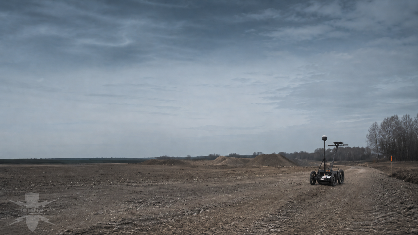
Whether historical aerial photograph analysis, explosive ordnance surveying, surface surveying using GPR, magnetometry or TDEM, deep-ground surveys, downhole surveys, excavation supervision, area clearance or ordnance recovery is needed depends on the location, ground disturbance, depth, ground and existing documents. An early ordnance assessment provides clarity for tendering, programming, occupational safety and construction.
FONTANA-EOD combines its Section 7 SprengG licence, specialists holding Section 20 SprengG certificates of competence, suitable survey and clearance methods, and traceable documentation. Send the site plan, depth of ground disturbance, construction phase and existing documents for an initial technical assessment.


