Project pathway
The quickest route to the right decision.
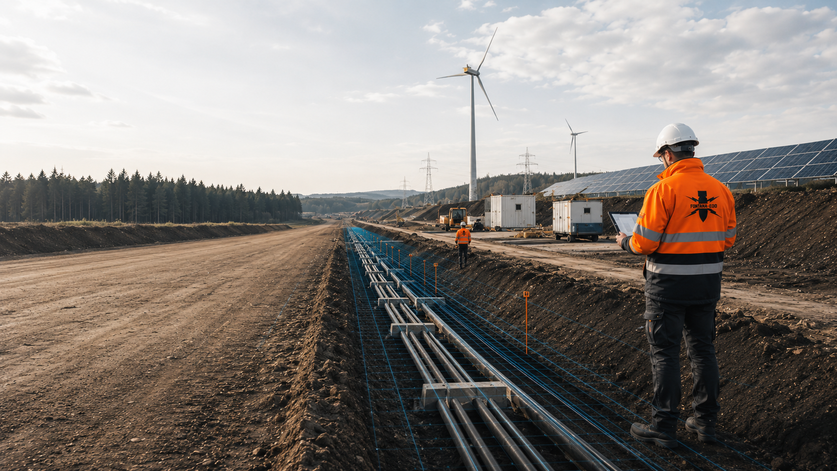
For a solar park, we consider driving locations, cable trenches, stations and ancillary areas involving planned earthworks. FONTANA-EOD plans suitable investigations according to the plant layout, depth of intervention, foundation method and construction phase. Send the project boundary polygon, layout, foundation points and construction sequence so that services and documentation needed can be defined before driving, cable excavation and station construction.
Assign module fields and plant areas.
Investigate driving locations, trenches and foundations.
Clearly document the areas dealt with.
Before driving and civil engineering work at a solar park, existing indications of a suspected hazard are used to clarify which explosive ordnance investigations the planned interventions need. Foundation points, cable trenches, stations, storage systems and access routes are recorded in the plant layout with positions, depths and construction methods. Historical assessment and technical investigation are aligned with these volumes of ground; existing installations and ground conditions also determine the capabilities of the methods. The documentation shows areas addressed, methodological limitations and outstanding tasks for the construction sequence.
The service scope for “Xanten solar park project” comprised ordnance specialist supervision during construction / technical supervision.
Service period: 2021-11
Service areas:Ordnance specialist supervision of groundworks
View project details · Ordnance specialist supervision of groundworks
A solar park is not a uniform construction area. Module rows, station locations, cable axes, access routes and the grid connection differ in depth of intervention, construction method and subsequent purpose of the documentation.
The explosive ordnance assessment is therefore planned by block, line and point. Design changes or relocated plant components are checked against the scope already documented.
For construction, the permanent plant area, temporary ancillary construction areas and extensions defined only later are also distinguished. This distinction matters because driving, cable installation, assembly and grid connection take place at different times and different contractors may work with differing plan versions.
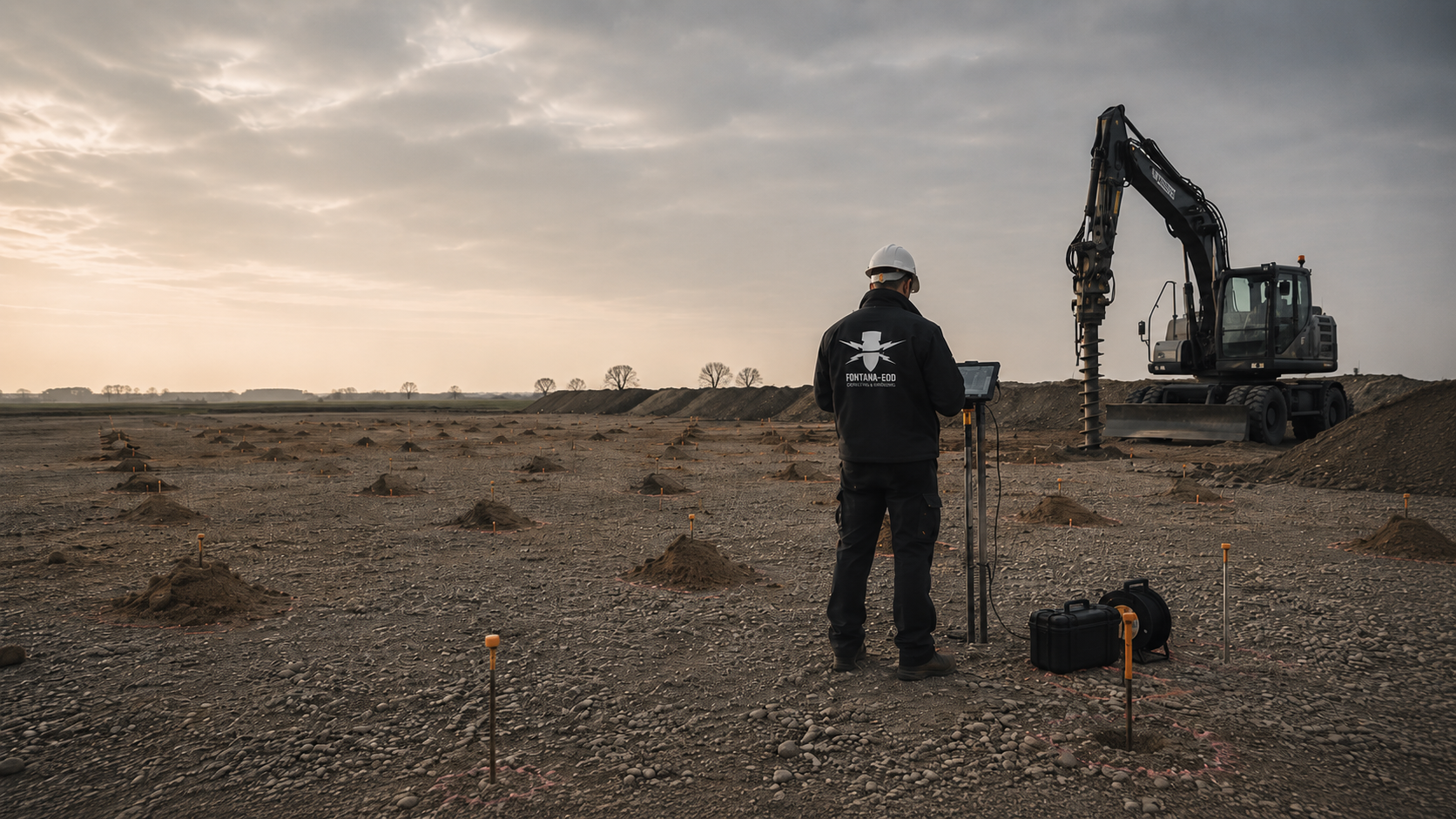
Driven posts, screw foundations or other support structures create numerous recurring localised ground interventions within clearly defined module blocks.
The grid, foundation depth, installation method and possible alternative positions determine which volume must undergo specialist assessment before installation.
Subsequent assembly may refer only to points actually investigated or clearly documented area sections.
Investigate driving and foundation points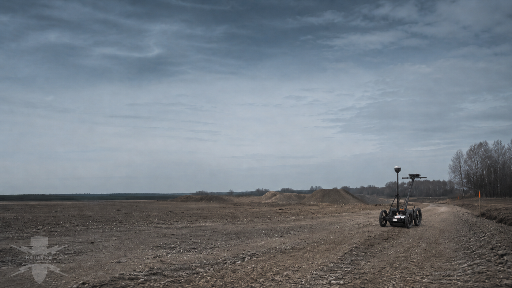
DC and AC cables, communication lines and earthing systems run between module fields, inverters, transformer stations and handover points.
Trench width, base depth, crossings and the planned construction sequence are documented by chainage or block.
Cable axes relocated or added later need checking against the existing work status.
Assess internal cable routesTransformer stations, inverter stations, battery storage systems and switchgear buildings create foundations, standing areas, cable entries and, in some cases, deeper earthworks.
The plant areas are recorded as separate construction sites with layouts, foundations, excavation depths and utility connections.
An area investigation of module rows does not automatically cover these locally deeper structures.
Assess station and storage areasSite roads, turning areas, crane and assembly areas affect additional areas through soil removal, aggregate installation, drainage or ground improvement.
Even temporarily used areas may be relevant to explosive ordnance investigation where they lie outside the plant layout previously considered.
The limits of the work addressed are coordinated with logistics, earthworks and assembly planning.
Record construction and logistics areas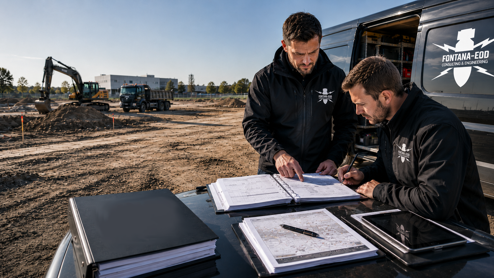
Fence posts, gates, drainage ditches, swales and culverts create long linear or localised interventions around and within the solar park.
Boundary shifts and later additions in particular are often defined only during construction design.
The documentation must therefore show which axes and points were actually covered.
Document boundary and drainage areasThe grid connection may leave the plant site and form a separate project corridor involving cable routes, crossings, transfer stations or substation areas.
The project boundary, changes of ownership, operator requirements and differing construction times are considered in explosive ordnance planning.
The internal PV site and external grid connection receive coordinated but individually unambiguous work statuses.
Coordinate the grid connection and plant areaExplosive ordnance assessment should be updated as the project develops. An early site layout needs different conclusions from driving and cable plans ready for construction.
Project development, EPC, HSE and site management therefore need a reliable status for each plant block and component as well as a report. Before handover to the driving crew, civil engineering teams or station construction, investigation results and unresolved areas are checked for the respective plant block.
Before lease, purchase or a binding site decision, historical indications, previous uses, known finds and existing authority documents are related to the project boundary polygon.
The result shows which subareas should undergo more detailed investigation and whether plant layout options require different assessments.
The early assessment clarifies further investigation needs. It does not replace necessary technical investigation of the interventions ready for construction.
Assess the project area historicallyModule blocks, the driving grid, station areas, storage systems, cable axes, access routes and drainage are translated into specific investigation geometries.
Plan versions receive unambiguous version numbers so that fieldwork is not based on an outdated layout.
Changes between approval, tender and construction design are checked by specialists against earlier documentation.
Have the construction design assessed by specialistsThe scope of services, area and point quantities, methods, preparatory work, interference zones, data formats and acceptance criteria must be comparable for all bidders.
Provisional items are linked to traceable triggers such as design changes, lack of access or areas that cannot be technically evaluated.
The tender distinguishes historical assessment, fieldwork, work on anomalies and measures during construction.
Prepare tendering and documentationDriving trials, geotechnical boreholes, probing and test fields often involve ground interventions before construction itself starts.
Coordinates, design depths, equipment use and the volume of ground required are recorded for these early interventions.
Clearance of a later module grid must not be inferred from a few early test points.
Prepare test and drilling pointsDriving crews, cable excavation, station construction, road construction and fencing teams may work simultaneously in different blocks.
Project management needs an up-to-date daily status for areas addressed, restricted areas and unresolved areas.
Stopping points and reporting procedures define which work is interrupted if an anomaly arises and who informs the affected trades.
Hand over work status to the tradesRelocated module rows, additional storage systems, changed stations or a later extension area may lie outside the original investigation area.
Before execution, it is assessed which existing data can be reused and where supplementary investigation is required.
An earlier report continues to apply only to the investigation area described in it.
Check design changes against documentationEach project phase needs a different conclusion. The basis for suspicion, technical survey feasibility and actual intervention are assessed separately and then brought together using the same location reference.
Aerial photographs, archives or authority documents establish a suspected area within or beside the planned solar park.
The next step is spatial assignment to module blocks, stations and cable axes and definition of suitable technical investigation areas.
The historical finding alone does not establish which objects are present in the ground today.
Relate the suspected area to the layoutArable land, grassland or conversion sites may be accessible over large areas and enable systematic surveys.
The target object, ground conditions, moisture, terrain, vegetation and required depth determine which method can actually provide meaningful conclusions.
The survey area is overlaid with the module grid, cable trenches and peripheral areas.
Define the area investigation methodologyOld installations, scrap metal, utilities, foundations, fill or previous commercial use can obscure survey data.
Known sources of interference are mapped. Supplementary methods and suitable survey access are assessed for zones that cannot be adequately evaluated.
An area with technical limitations is not documented as showing no anomalies.
Determine suitable methods for interference zonesA transformer station, battery storage system, transfer structure or deeper foundation points extend beyond the near-surface module area.
The investigation geometry follows the coordinates, excavation, foundations and utility entry of the specific structure.
Area survey and deep point investigation are recorded separately in the project file.
Investigate deep plant pointsVegetation, water, existing structures, ongoing use or a missing plan version can prevent advance investigation.
The area is identified on the plan as not yet adequately investigated. Suitable supplementary methods and possible access after site preparation or demolition are defined. Necessary investigations and protective measures are planned before ground interventions during vegetation clearance, breaking out, demolition or preparation of access.
Site management receives an unambiguous designation rather than a blanket area conclusion.
Select investigation for later accessA survey anomaly is first checked for technical plausibility and distinguished from known technical installations.
Survey anomalies receive a specialist follow-up investigation or exposure. Recovery of confirmed explosive ordnance is coordinated with the permitted scope of activities and local responsibilities. If an unexpected suspicious object is found, work stops immediately and the competent authorities are notified without delay.
Position, handling, handover and unresolved areas remain linked to the original solar park section.
Clarify findings investigation and handoverThe documentation must show which areas, driving locations, cable axes and structures were considered using which method. It remains tied to the scope actually addressed.
Digital maps, point lists and reports are structured so that they can be incorporated into project and construction documentation. Design and as-built data remain distinguishable; even months later, it is thus possible to trace which layout version supports a particular conclusion.
The project boundary, land parcels, construction sites, module blocks and grid connection are maintained in an unambiguous coordinate and plan system.
Design changes receive dates and version references so that earlier investigations can be checked by specialists.
Peripheral or extension areas not included remain identifiable.
Aerial photographs, maps, archive information, previous uses and authority information are documented with sources and geographical scope.
Contradictions or missing imagery dates are identified as gaps in data.
The historical conclusion relates to the current solar park layout.
Survey grids, lines, driving or drilling points, cable sections and station areas receive unambiguous identifiers.
Coordinates, design depths and work status remain linked through planning and construction.
Changes to point positions are documented traceably with dates and plan versions.
Methods, ground conditions, surface, vegetation, moisture, utilities, interfering objects and access are described by section.
Areas that cannot be technically evaluated are shown spatially.
For each limitation, the technically intended follow-up measure is identified.
Anomalies, known installations, exposure work and actual finds are maintained in separate categories.
Each outstanding point receives a traceable decision and responsibility status.
Completed measures remain documented with dates, positions and type of work.
The report, maps, lists, records and digital data are handed over to project development, the EPC contractor and site management in the agreed structure.
The conclusion identifies the work status actually reached and remaining limitations.
Blanket conclusions about uninvestigated areas or areas changed later are avoided.
In the project file, early site assessments and later investigations are assigned to the respective layout versions. Each file receives an unambiguous reference to the project, block, point or route section.
The dossier can be consulted again during later maintenance, repair or extension work. The comparison between the original plant design and new intervention geometry is then decisive; only conclusions that match spatially and in depth are reused.
Preliminary design, approval layout, tender version and construction design are maintained with version control.
This keeps it traceable which plant design formed the basis of a historical or technical assessment.
Module fields, the driving grid, stations, storage systems, access routes and grid connection receive a consistent hierarchy.
Handovers between development, the EPC contractor and subcontractors retain the same location reference.
Survey areas, investigation lines, driving locations, drilling points and station areas are recorded with coordinates and status.
The list distinguishes planned, investigated, restricted, changed and unresolved.
Unusual findings, known installations and technical gaps in data are assessed separately.
Each entry receives a follow-up measure, priority and assignment to the affected construction section.
Working conditions, areas actually addressed, excavation layers and interruptions are documented continuously. Following actual exposure or clearance work, the corresponding findings and clearance records are included.
The records reflect the actual construction condition rather than only the original layout.
Maps, lists, records and conclusions are handed over according to the agreed data structure.
Later extensions can be added without overwriting the original work status.
The work is adapted to the development, approval and construction design stages. Early results remain usable but are not transferred to later layout changes without assessment.
Early ground investigation or driving trials are maintained as separate initial work packages. Their results can support later planning but do not replace investigation of additional points, deeper structures or changed cable and station positions.
The project boundary polygon, land parcels, project phase, plant concept and decision needed are described.
Aerial photographs, maps, previous uses, authority information and known finds are related to the project area.
Module blocks, the driving grid, cable axes, stations, storage systems, access routes and grid connection are recorded separately.
Survey feasibility, ground conditions, sources of interference, depth and construction method determine methods, grids and supplementary services.
Access, vegetation, surveying, occupational safety, construction times and data handover are coordinated before work begins.
Areas, points and excavation sections are addressed according to the agreed geometry and methodology.
Survey values, anomalies, limitations and exposure work are checked for plausibility against the layout and basis for suspicion.
The report, maps and outstanding measures are prepared for the EPC contractor and site management and supplemented when plans change.
Solar parks combine recurring foundation points with long cable axes and individual deeper structures. Technical investigation must distinguish these geometries while bringing them together in a common project file.
The technical description considers more than the plant that will later be visible. Temporary vehicle routes, storage zones, assembly areas and working spaces around stations may also affect the ground and must be checked against the documented investigation area before use.
Module fields are described by block boundaries, row axes, driving or screw foundation points, possible alternative positions and intended foundation depths. An area investigation can support the grid, but must show which point-specific volumes at depth are actually covered.
Cable trenches, drainage and fence axes are recorded as linear working corridors. Station, storage and transfer areas receive their own structure geometries with excavation, foundations and cable entries. Test piles, geotechnical boreholes and test fields are documented as early individual points.
The work status remains tied to the current plan. If a station moves, a new storage area is added or the cable route changes, the new geometry is checked against existing documentation. The comparison shows which results remain applicable and where supplementary investigations are needed.
The block boundary, row spacing, point list and foundation depth provide the basis for area-wide and point-specific investigations.
Alternative points are included only where they lie within the documented area.
The axis, working width, base depth, slopes or retaining structures and crossings determine the linear investigation area.
Internal and external cable sections remain separately assignable.
The foundation layout, excavation, foundation system, standing area and utility entries are considered as a separate construction site.
For deep structures or structures added later, the additional investigation needs are clarified.
Soil removal, sub-base installation, drainage and lateral working spaces determine the actual intervention.
Temporary logistics areas are not left outside the project investigation.
Posts, gates, swales and culverts create numerous peripheral points and lines.
The construction axis is checked against the land parcel boundary and existing investigation areas.
The layout version, block addressed, outstanding point and handover status are maintained continuously.
Only documented areas are handed over to the next trade.
Existing suspected hazard documents are compared with module fields, foundation points and cable routes. Transformer stations, storage systems, access routes and temporary construction areas are included where ground interventions are intended. A changed plant arrangement requires a new spatial comparison.
Check documentation against the current plant layout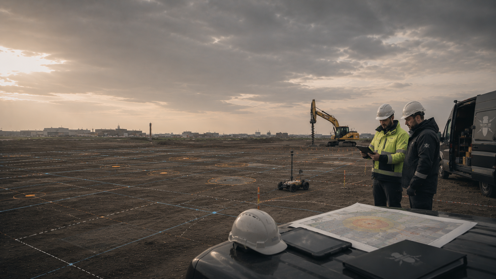
Driven posts, screw foundations, point foundations and deep station areas may need different investigations. For selection, positions, dimensions, embedment depths and installation methods are stated. Survey limitations and areas not yet accessible remain explicitly assigned.
Select investigation for the foundation typeThe methods measure different physical properties and have their own spatial limitations. They are combined according to the project question rather than specified as interchangeable alternatives.
Assesses suspected areas, previous uses and gaps in data within the project area.
It does not establish the presence of objects actually in the ground today.
The result determines the priority and scope of technical investigation.
Detects ferromagnetic anomalies on suitable, accessible open areas.
Utilities, scrap metal, vehicles and metal installations can limit evaluation.
Suitability depends on the target object, grid and interference environment.
Detects electromagnetic responses from conductive objects and can provide supplementary assessment of certain anomalies.
Ground conditions, depth and technical infrastructure influence the conclusions.
The method does not replace a deep-ground investigation required by the geometry.
Shows reflections at material and structural boundaries and can provide additional information in suitable ground.
A reflection does not automatically identify explosive ordnance.
Moisture, ground conditions and heterogeneous fill determine data quality.
Investigates defined points and volumes at depth for stations, storage systems, boreholes or other deep interventions.
Coordinates, design depth and subsequent working geometry must align.
It does not address the entire module area outside the defined points.
Where explosive ordnance detection during construction is technically suitable, each working layer is surveyed and evaluated using technical methods. Controlled removal in layers and supplementary visual inspection then follow; these steps are repeated down to the agreed excavation base.
Excavation layers, stopping points, authority to give instructions, communication procedures and documentation are defined in the work instruction before work begins. Merely watching the excavator at work is insufficient.
The conclusion applies only to the working area actually supervised.
Project development, the field team and site management use the same area and point identifiers. Before execution, the layout version, survey results and outstanding tasks are checked against each other.
Even in large installations, every survey result must be assignable to a layout version, construction section and respective work status. Surveying, file naming and handover rules are therefore defined during work preparation.
FONTANA-EOD first reviews the current plant layout and clarifies why you need the results. The overall site is divided into technically and organisationally appropriate volumes of ground affected.
Methods are selected according to the target object, depth, ground conditions, sources of interference and access. Areas that cannot be evaluated and design changes remain identifiable and receive a clearly named follow-up measure.
Fieldwork is linked to surveying, the plant layout, EPC organisation and the construction programme. Trades working simultaneously can thus use a consistent work status.
Reports describe the area actually investigated and method used. They are not framed as blanket conclusions covering later extensions, greater depths or changed construction methods.
The area, component, depth, construction phase and decision needed are defined before work begins.
Module blocks, points, cable axes and stations retain unambiguous geographical references.
Methods are selected according to survey feasibility and the target object rather than equipment availability.
Design changes and unresolved areas are checked against the earlier work status.
The EPC contractor, HSE, site management and specialists involved receive defined reporting and handover procedures.
The documentation identifies the status, limitations and next technical step.
Investigation, evaluation and handover of results are planned before the respective foundation and trench works. Vegetation, ground conditions and preparatory work influence when an area is accessible. Unresolved areas remain identifiable in the construction sequence.
Relocated rows, additional stations and new cable crossings are compared with the documented investigation scope. The current plan version shows which results remain relevant and which interventions need supplementary investigation.
Project developers, landowners, designers, the EPC contractor, subcontractors and competent authorities have different tasks. Before work begins, it is defined who reports design changes, receives results and commissions outstanding investigations.
Define the project objective, layout version, programme, tendering model and documentation needed.
They provide available site and suspected hazard documents and commission the specialist services required.
Support access, knowledge of previous uses, vegetation management and definition of available working areas.
Ownership or usage rights do not replace a specialist assessment of ground conditions.
Translate the project into module blocks, foundations, cable axes, stations, storage systems and ancillary construction areas.
Changes are handed over so that their effects on the earlier investigation status can be assessed.
Implement investigated working areas, construction phases, stopping points and communication procedures.
Different points, additional trenches or changed construction methods are reported before execution.
Assesses documents and the suspected hazard, plans the commissioned approach and records results and limitations.
The service remains tied to the assignment, volume of ground affected and actual execution.
In Germany, the ordnance disposal services of the federal states and the locally competent authorities carry out hazard-response and find-management duties. Their involvement is established for the project location; outside Germany, local responsibilities apply.
The local public order authority and, where applicable, building control are involved according to their project-specific responsibilities. Conditions and contacts are assigned to the actual plant fields and construction sections. If an object is found, the competent authorities determine the next steps.
Requirements depend on the activity, project location, construction condition and possible circumstances of finds. The specification, qualifications, risk assessment and documentation are therefore defined for the project.
Site organisation also considers that electrical installations, driving equipment, civil engineering and assembly have different hazards and areas of responsibility. The explosive ordnance service is incorporated into this overall organisation without replacing other specialist tasks.
In Germany, § 7 SprengG concerns the commercial authorisation for activities requiring authorisation; § 20 SprengG concerns the certificate of competence of responsible persons. Under § 1b SprengG, searching for found munitions also counts as handling them. The requirements applicable to the project depend on the activity actually commissioned and the allocation of responsibilities.
The risk assessment connects methods, personnel, equipment, driving and earthworks, protection zones, escape routes, weather conditions and communication. Trades working simultaneously and changing construction sections are explicitly considered.
DGUV Information 201-027 supports risk assessment and protective measures for explosive ordnance clearance work. The Baufachlichen Richtlinien Kampfmittelräumung contain requirements for historical and technical investigation, clearance concepts, procurement and documentation within their defined scope of federal responsibilities. Their application to the specific solar park project is clarified separately.
If an unexpected suspicious object is found, stop work in the affected area immediately. Do not touch, move or further expose the object. Leave the danger area and keep others away without putting yourself at risk. In Germany, notify the police immediately on 110; outside Germany, use the local emergency reporting procedure. The competent authorities determine the next steps. Then inform site management and those responsible for the project.
The First Ordinance to the Explosives Act (1. SprengV) includes requirements concerning specialist competence and state-recognised training courses. In solar parks, the required qualifications are determined by the actual investigation or clearance assignment within the respective plant area.
DGUV Rule 113-003 concerns the dismantling or destruction of explosives or corresponding objects and also includes the disposal of found munitions. It applies according to this field of activity; it does not replace a risk assessment specific to the planned ground intervention.
The company, responsible persons and scope of activities must align technically and under explosives legislation.
Driving, civil engineering, electrical installations, parallel trades, protection zones and reporting procedures are assessed by section.
Areas, points, depths, methods, preparatory work, quality control and documentation are clearly defined.
Site management, HSE, the project developer and competent authorities follow a procedure clarified in advance.
The layout version, quantities, methods, qualifications, data formats and acceptance criteria are described to enable comparable tenders.
Unclear provisional items receive a technical trigger.
Access, vegetation, surveying, working areas, equipment, instruction and stopping points are checked against the applicable plan version.
Changes are considered before mobilisation.
Stop work immediately, do not touch, move or uncover the object further, leave the immediate area and keep others away without putting yourself at risk. In Germany, notify the police immediately on 110. Outside Germany, use the local emergency reporting procedure.
The further decision depends on the circumstances of the find and regional responsibilities.
Plans, point lists and records show which areas were investigated and which tasks remain unresolved.
Each representation receives a reference to the current plant layout.
The PV layout connects module fields, driving locations, cable axes, stations, storage systems and ancillary construction areas with their respective investigation statuses.
Assess PV installations within the energy project
Solar park-specific mapping defines suspected areas, gaps in sources and priority investigation areas within the project boundary polygon.
Assess historical suspected areas
Depth-related documentation for the solar park is limited to the recorded points, design depths and structure geometries.
Investigate driving and station points with reference to depth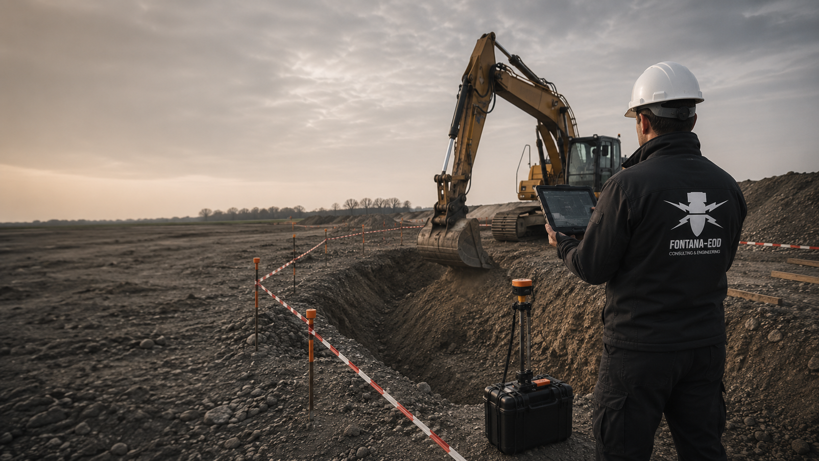
The suitability of construction-phase ordnance surveying is assessed for each excavation layer. The documented investigation area limits the statement’s scope.
Supervise cable trench and excavation works
The solar park file distinguishes the survey anomaly, technical installations, confirmed find and outstanding work for each plant block.
Document findings and work status for each plant block
Historical evidence, fieldwork, layout version, limitations and next decision are documented together for the solar park.
Document the PV project file and handover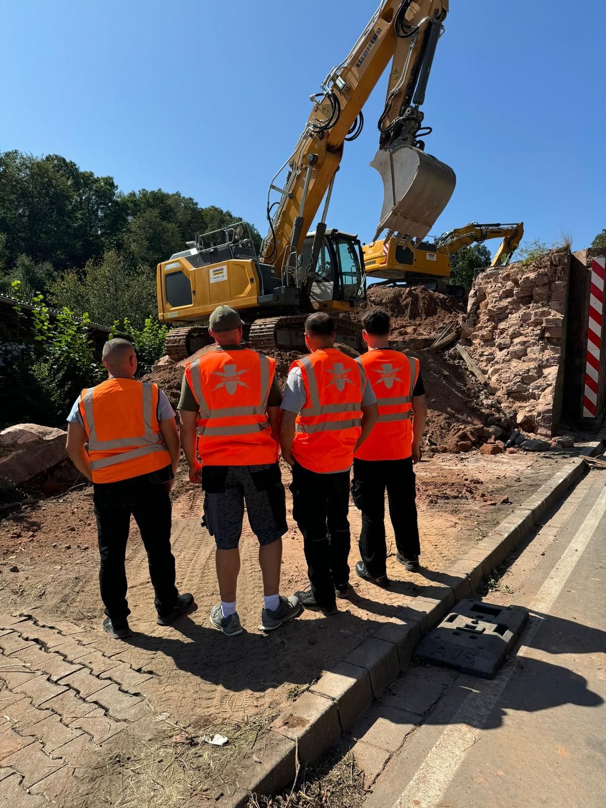
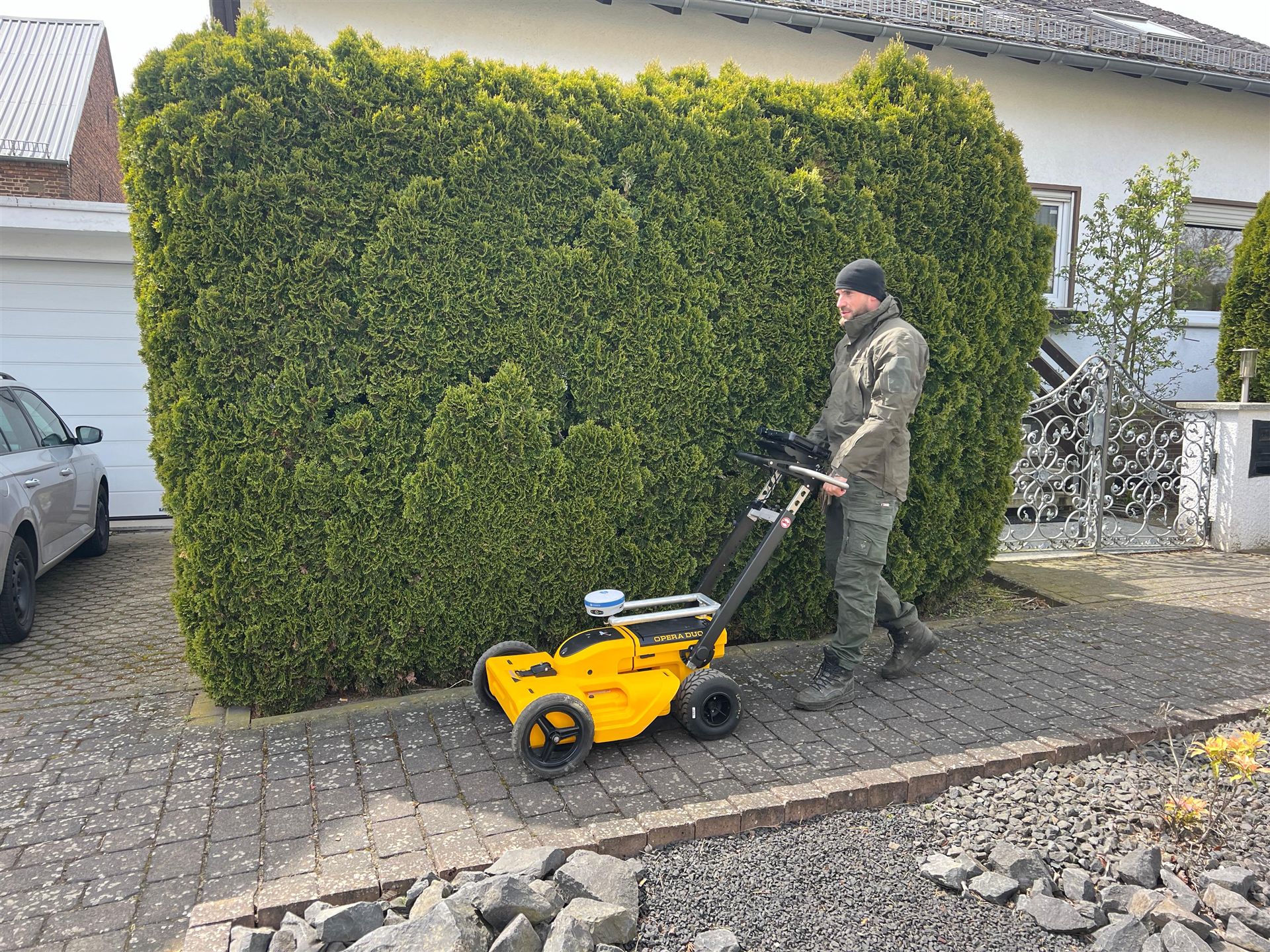
Historical clarification of suspected hazards, deep-ground investigation, excavation supervision, work on finds and documentation are assigned to the respective affected plant area.
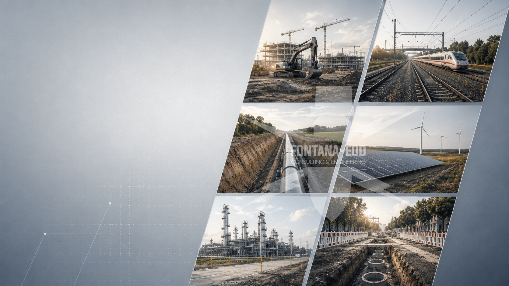
Plan ordnance assessments for transport, utility, energy and other infrastructure projects according to their ground interventions.
Have the project surroundings assessed by specialists
Distinguish utility corridors, crossings, foundations and installation areas by construction method and intervention depth.
Assess utility and energy project requirements
Provide spatial justification for suspected areas, gaps in data and technical priorities for solar parks and ground-mounted PV.
Clarify historical suspicion indicators
Relate boreholes, foundations, chambers and deep points in solar parks and ground-mounted PV sites to the subsequent volume of ground affected.
Assess deep spaces affected by the works
Establish the suitability and sequence of construction-phase ordnance surveying for remaining excavation areas.
Prepare the excavation sequence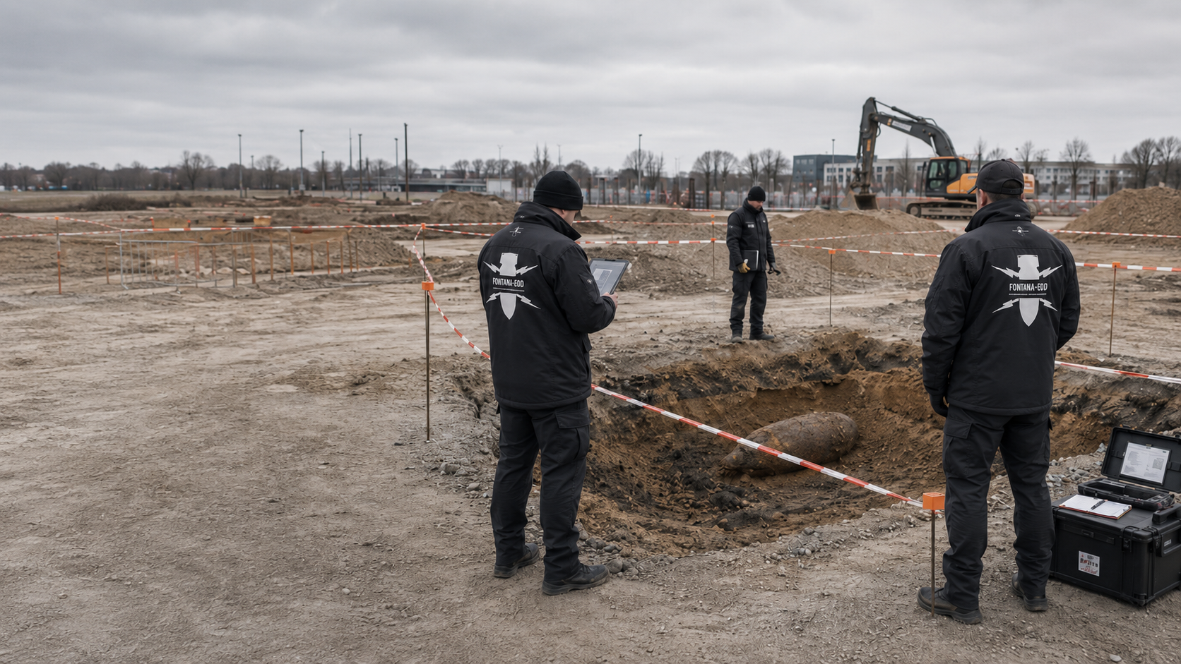
Coordinate recovery of confirmed ordnance with the permitted activities and local responsibilities.
Coordinate the processing of findings
Define the specification, data structure, quality control and partial handovers for solar parks and ground-mounted PV.
Prepare tendering and documentation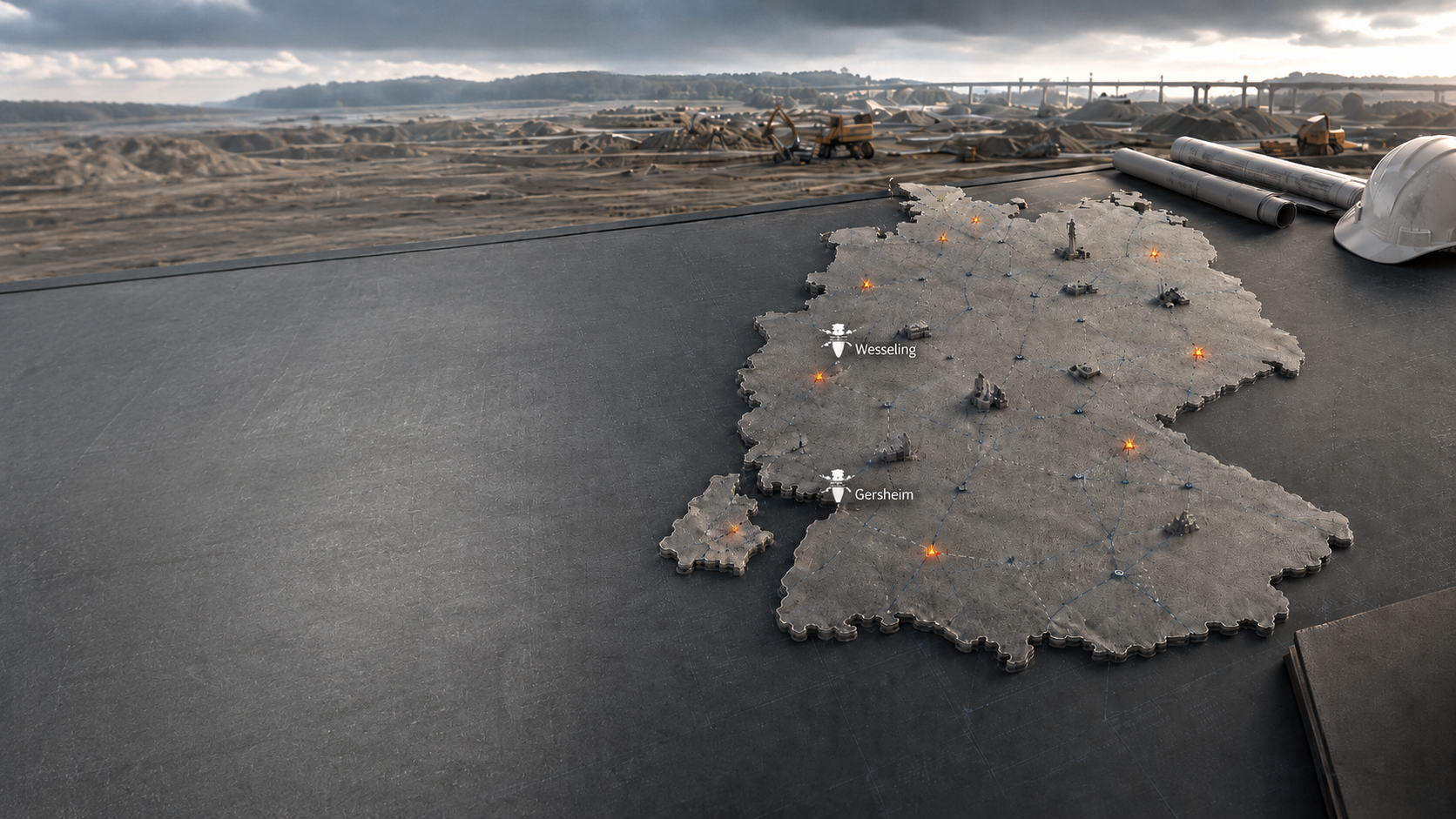
Consider the project location, federal state and local interfaces for planning and communication about finds in solar parks and ground-mounted PV sites.
Understand regional responsibilities
Have the site plan, working geometry, plan version and decision date for solar parks and ground-mounted PV assessed by specialists.
Enquire about your solar park with documentsState the project location, land parcels, field identifiers and plant locations. The site plan and foundation schedule must use the same version. Existing requirements and reports are assigned to the respective fields, cable sections and access routes.
A result for an area describes only the documented position and depth. Compare this volume with the intended embedment of posts and deeper station or storage foundations. Blanket transfer to all plant points is not possible.
Check evidence against the interventionGround reshaping may change the reference for subsequent foundation depths. Record the reference levels traceably in the plan and investigation report and recheck changed depths before installation.
Explore the technical principlesTechnical information
Utility routes, substations and energy installations place different demands on ordnance assessment. The brochure shows the design information needed and how investigation, construction sequence and documentation fit together.
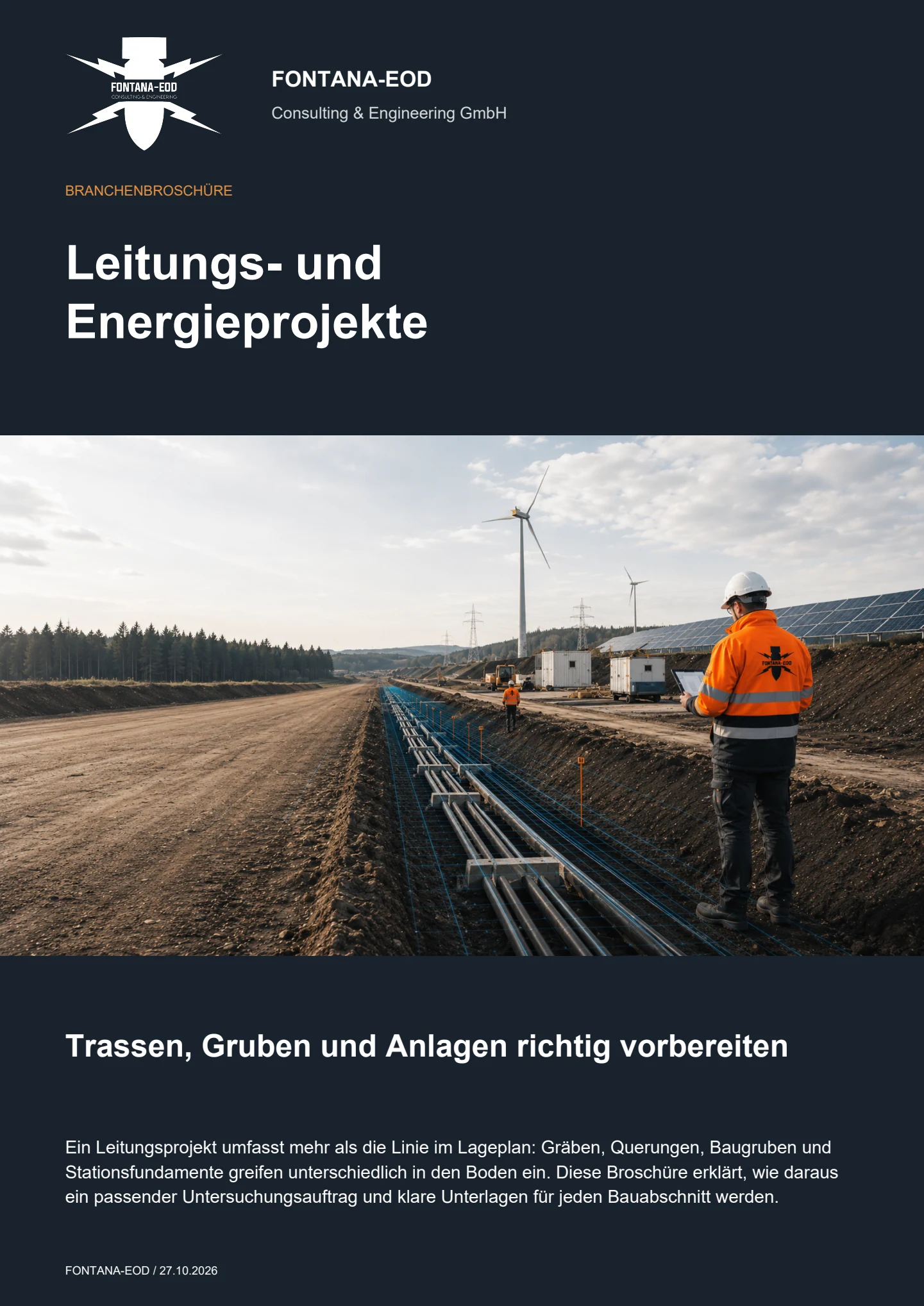
Specialist assessment should start once the project boundary polygon and main construction components are known. During early phases, the historical suspected hazard can be assessed first. Before driving works, geotechnical boreholes, cable trenches, station foundations and access route construction, the specific volumes of ground affected must be established by position, depth and survey feasibility.
This depends on the suspected hazard, foundation method, grid, ground conditions, survey method and achievable conclusions. An area investigation can cover numerous points where its geometry and depth suit the later intervention. Points extending deeper, relocated or outside the survey area need separate assessment.
If an unexpected suspicious object is found, stop work. Do not touch, move or uncover it further. Leave the immediate area and warn others without putting yourself at risk. In Germany, notify the police on 110; outside Germany, use the local emergency reporting procedure. The competent authorities determine what happens next; a project enquiry does not replace reporting the find.
Useful documents include the project boundary polygon, land parcels, current PV layout, driving or foundation points, cable and drainage axes, station and storage areas, grid connection, ground investigation data, utility plans, historical assessments, conditions, construction times and desired date for handover of results.
Information and requirements from authorities are supplied with their date, complete appendices and geographical scope. In Germany, the competent ordnance disposal service, local public-order authority and, where relevant, building-control authority are identified for the project location; outside Germany, local responsibilities apply.
Known utilities, scrap metal, foundations, fill or previous uses are documented as sources of interference. Areas that cannot be adequately evaluated are identified on the plan, and suitable supplementary investigations and possible access after site preparation or demolition are defined. Where explosive ordnance detection during construction is technically suitable, each working layer is technically surveyed and assessed before controlled removal with supplementary visual inspection follows. Necessary investigations and protective measures are also planned before preparatory ground interventions; areas not covered remain unresolved.
Relocated module rows, additional storage systems, changed stations or new cable axes are checked against the existing scope addressed. If the new geometry lies outside the documented area, depth or point list, supplementary services are planned. The earlier report remains traceable without alteration.
In Germany, the federal states' explosive ordnance disposal services and locally competent authorities perform emergency response and work on finds. Outside Germany, local responsibilities apply. The commissioned specialist company addresses the agreed investigation and documentation scope for the solar park. Reporting procedures and contacts are clarified for the affected construction sections before work begins.
Influencing factors include the project area, number and depth of foundation points, cable and fence lengths, station areas, vegetation, ground conditions, utilities, interfering objects, access, methods selected, construction phases, data formats and extent of documentation. Reliable pricing therefore requires a current layout and clear intervention geometry.
An initial enquiry may be based on an early plan version. The project area, main construction components, intended foundations and next decision needed should be identifiable.
For installations with several construction sections or separate EPC lots, priorities, handover points and desired data formats should be stated in the enquiry. The service can thus be divided into appropriate, verifiable work packages.
Send the site plan, land parcels, project boundary polygon, module blocks, peripheral areas and current version.
Mark options, extension areas and areas not yet accessible or defined in planning.
For large installations, the intended block and section structure should be identifiable.
Describe driven posts, screw foundations, boreholes, cable trenches, drainage, stations, storage systems, fence points and access routes.
State design depths, excavations, working widths and possible alternative positions.
The external grid connection is identified as a separate route or plant area.
Attach utility plans, ground investigation data, historical assessments, authority correspondence and known interference areas.
State the project phase, tender date, preliminary geotechnical works, construction start, parallel trades and required handover date.
Incomplete documents also show which evidence still needs to be obtained.
The project boundary polygon, current layout, foundation types and depths, cable and station planning, planned construction start and existing indications of a suspected explosive ordnance hazard often suffice for an initial assessment. FONTANA-EOD then identifies the required scope of services and data.
For staged solar park projects, work can be divided according to construction readiness and priority. The EPC contractor thus receives reliable conclusions for upcoming blocks without prematurely defining later or still-changing areas.
Project boundary polygon, land parcels, module blocks, peripheral areas and current plan version.
Driving and drilling points, cable trenches, stations, storage systems, fences and drainage.
EPC model, preliminary geotechnical works, construction phases, parallel trades and handover dates.
Basis for tendering, HSE, site management, the network operator, project file or subsequent decision.
Whether historical aerial photograph analysis, explosive ordnance surveying, surface surveying using GPR, magnetometry or TDEM, deep-ground surveys, downhole surveys, excavation supervision, area clearance or ordnance recovery is needed depends on the location, ground disturbance, depth, ground and existing documents. An early ordnance assessment provides clarity for tendering, programming, occupational safety and construction.
FONTANA-EOD combines its Section 7 SprengG licence, specialists holding Section 20 SprengG certificates of competence, suitable survey and clearance methods, and traceable documentation. Send the site plan, depth of ground disturbance, construction phase and existing documents for an initial technical assessment.


