Project pathway
The quickest route to the right decision.
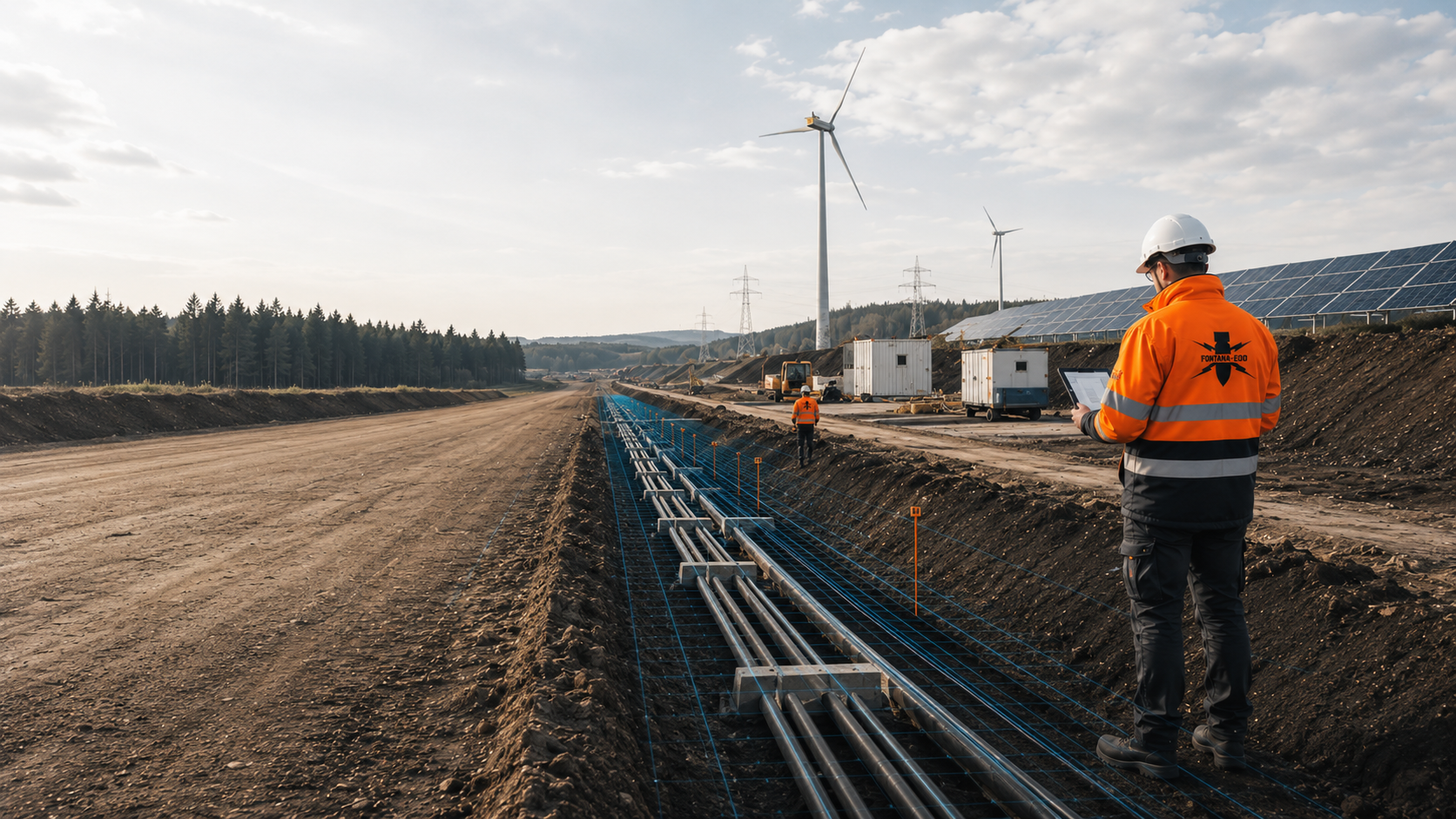
Before work at a substation or transformer station, foundations, cable routes, earthing systems and ancillary areas are checked against the available explosive ordnance records. FONTANA-EOD plans suitable surveys according to the installation layout, depth of intervention, existing infrastructure and operational access. Send installation and foundation plans, point lists, depths and construction phases so that services and documentation can be defined before earthworks, drilling and foundation work.
Identify foundations, cable routes and ancillary areas.
Record piles, gantries and excavations.
Coordinate access, shutdowns and documentation.
Before earthworks and foundation work, existing hazard indications and planned ground interventions are used to clarify which explosive ordnance surveys are required. Foundations, cable channels, earthing systems, drainage, access roads and excavations are considered. The detailed construction geometry of each component is decisive; a general area figure for the operating site is insufficient for deep or individual point interventions.
Five borehole surveys are documented at the DB transformer station at the Saarbrücken maintenance facility. The documentation relates to this survey scope. View project details.
Service areas:Downhole magnetometry / deep-ground survey
A substation consists of different construction and operational zones. Transformer foundations, gantries, cable channels, operational buildings, access roads, drainage and earthing systems differ in area, depth and interference from technical installations.
The explosive ordnance assessment therefore follows the specific installation layout and construction phase plan. Each volume of ground is assigned its own work status, which can subsequently be carried through into tendering, site management and project records.
Where operations continue, work boundaries, access conditions, shutdowns and safety zones are coordinated with the technical assessment. Inaccessible zones are not given a blanket assessment; they are identified for a later construction stage or a suitable alternative measure.
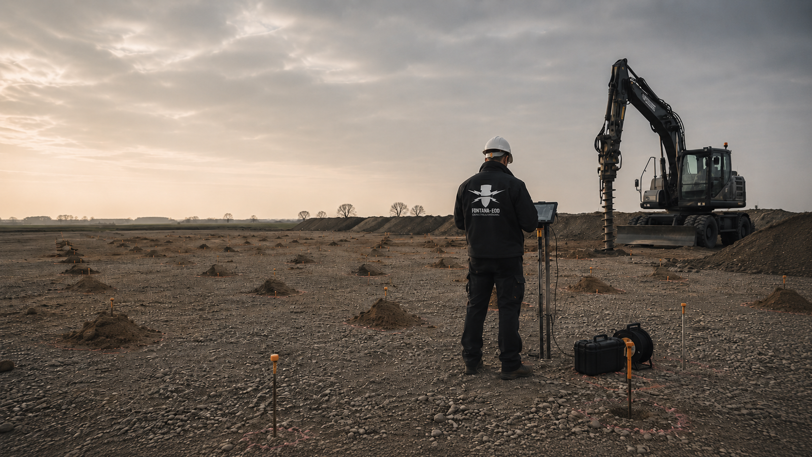
Transformers, compensation equipment and switchgear require load-bearing foundations, oil containment structures or deeper foundation elements. The assessment relates to foundation dimensions, excavation depth, piles and possible underlying structures.
Near-surface surveys do not automatically assess the full volume at depth. For pile or borehole locations, we check whether existing surveys cover the required depth and what additional work may be needed.
Assess foundation and deep intervention points
Cable routes run between switchgear bays, transformers, operational buildings and grid connections. Depth, width, crossings and existing cables determine the actual volume of ground affected.
Existing cables, metal installations and earthing conductors can limit survey feasibility. The utility trench is therefore planned in sections and linked to the construction stage.
Select methods for cable trenches and channelsGantries, busbar supports, lightning protection masts and overhead line pylons involve numerous individual foundations. Point location, target depth, diameter and installation method must be consistent with the survey plan.
Relocated or additional points are not assumed to be covered by an earlier area assessment; they are reassessed against the documented survey geometry.
Prepare gantry and mast locations
Switchgear buildings, protection and control buildings, workshops and storage areas require excavations, ground slabs, service connections and often additional foundation points.
The building area is considered as a connected volume of ground affected, including external works, cable entries and drainage. This makes the interfaces between building construction and installation construction identifiable on the plan so that outstanding surveys can be checked.
Assess the building area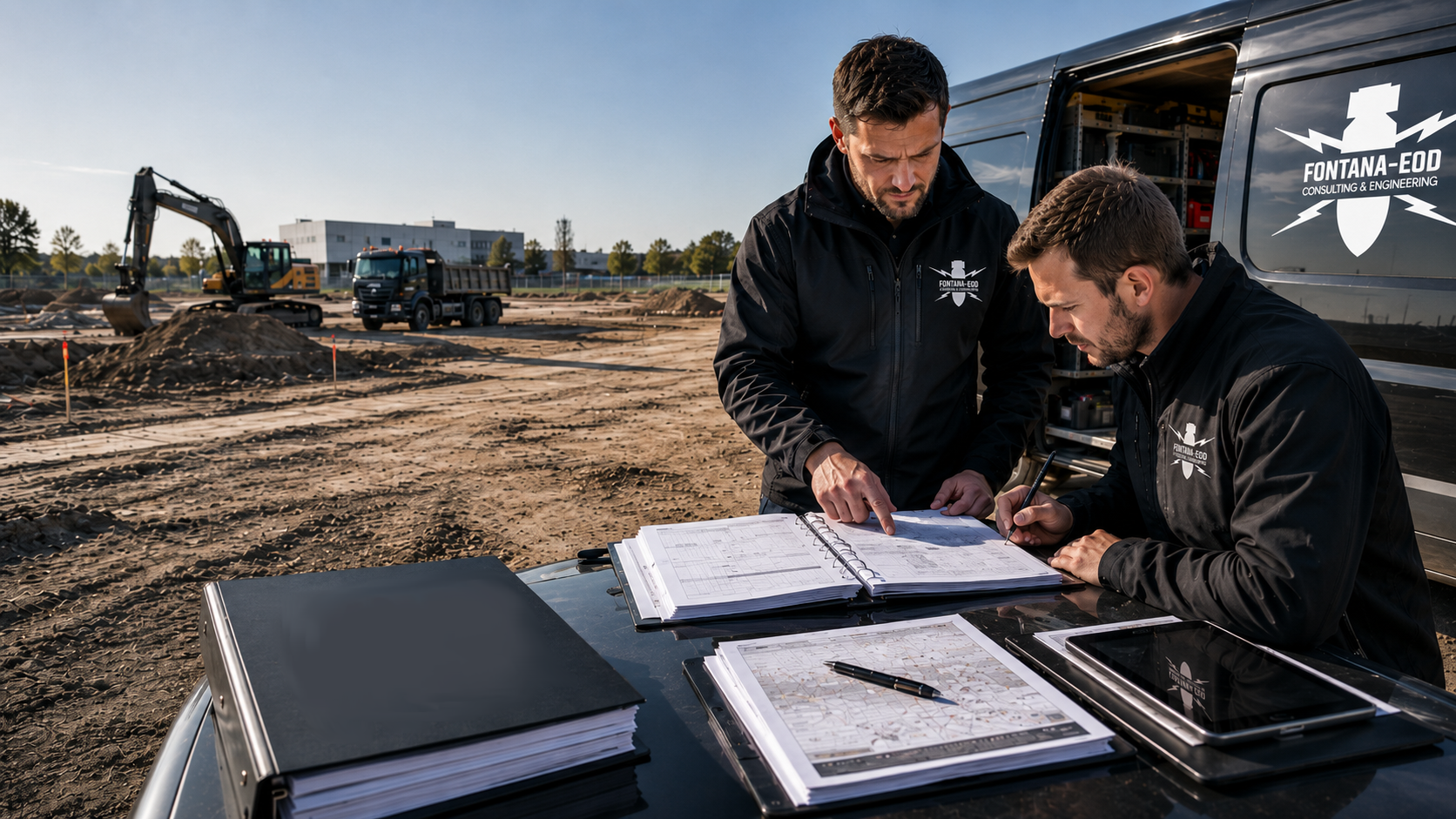
Swales, channels, chambers, retention basins, oil separators and firefighting water systems may lie outside the switchgear bays themselves while still involving substantial ground intervention.
These structures are included in the assessment area with their location, depth and excavation geometry. Later design changes are checked against the existing status of work.
Match ancillary installations to documentationHeavy-load access roads, crane standing areas, assembly areas and temporary cable routes may require ground improvement, excavation or load distribution measures.
Temporary areas are also assessed where ground intervention is involved. The documentation distinguishes permanent installation areas from temporary construction work zones.
Assess logistics and assembly areasSubstation projects develop from site and option comparisons to a detailed installation layout. Foundations, cable routes, excavations and temporary areas are defined more precisely at each design stage.
The explosive ordnance assessment is updated when components, depths or construction phases change. An early area assessment is checked against newly added deep intervention points or relocated installation alignments. This establishes what supplementary work is required.
Before securing land or preparing the outline design, we clarify whether historical sources, previous uses or known finds establish a spatially defined suspicion.
The early assessment supports layout options and prioritises technical survey areas without providing a conclusive assessment of the ground for later construction.
Assess the site using historical evidenceAs soon as the locations of switchgear bays, transformers, operational buildings and cable alignments are defined, the suspected hazard areas are overlaid with the installation layout.
This creates specific area, linear and point assessment tasks for procurement, scheduling and HSE coordination.
Define the assessment scope for planningAreas, depths, methods, access, sources of interference, data formats and required documentation must be described consistently for all tenderers.
Generic explosive ordnance survey items are generally insufficient for installation sites divided into many different areas.
Prepare a service scope suitable for tenderingPiles, boreholes, masts, gantries and shoring alignments require assessment of the actual volume of ground affected at each point and depth.
Coordinates, target depth, diameter, installation method and safety distances are brought together before fieldwork.
Investigate deep foundation volumesExisting installations can restrict access and survey conditions. Dismantling, shutdowns and new construction are divided into stages so that newly accessible zones are assessed at the appropriate time.
Operational authorisation to work and the status of explosive ordnance work remain documented as separate decisions.
Coordinate modification phases and assessment timingA survey anomaly, a technical source of interference and an actual suspicious object must be distinguished.
If an unexpected suspicious object is encountered, work is stopped immediately and the responsible authorities are notified without delay. Work resumes in accordance with their instructions.
Document findings and subsequent decisionsHistorical indications, technical survey feasibility and the planned ground intervention geometry are initially considered separately. Suitable surveys are then selected for each installation area.
Area-based methods may be suitable on an open new-build site, while an existing installation area may be strongly affected by steel structures, cables and the earthing grid. The status of work is therefore recorded by component and section.
Aerial photographs, maps, archives or existing project records substantiate a possible suspicion in parts of the site.
The suspected hazard area is overlaid with the installation layout, excavations, cable routes and temporary areas.
The historical assessment leads to a prioritised technical assessment task; it does not yet describe an individual object whose presence has been demonstrated.
Define the spatial extent of the suspected hazard areaAn accessible area without dominant technical interference can be surveyed geophysically over its extent.
The method and survey grid depend on the target object, ground and surface conditions, required depth of usable data and subsequent excavation.
Marginal zones that cannot be surveyed remain visible on the site plan and are assigned their own follow-up measure.
Plan an area-based surveySwitchgear bays, masts, earthing conductors, transformers and utilities can obscure survey data.
The area is divided according to accessible zones, dismantling stages and available work windows.
Suitable supplementary methods and later survey access are assessed for areas that cannot be surveyed adequately. Explosive ordnance surveying during construction is an option only where technically suitable.
Clarify assessments and alternative measures in existing installation areasA planned pile, borehole or mast base affects a clearly defined volume at depth.
The assessment relates to the point location, target depth, drilling or installation method and existing utilities.
The result applies to the documented assessment geometry, not to neighbouring points or the entire installation site.
Survey the point location and volume at depthCable trenches, foundation repairs or dismantling areas may become fully accessible only during construction.
First, the technical suitability of explosive ordnance surveying during construction is assessed for each excavation layer. The working layer is technically surveyed and assessed before controlled removal in layers with supplementary visual inspection. These steps are repeated down to the agreed excavation base. Equipment use, hold points, authority to issue instructions, communication channels and documentation are defined before work begins.
The documentation describes only the areas and depths actually supervised.
Provide controlled supervision of an excavation sectionAreas with anomalous readings are assessed at their exact locations and compared with known installations and the project geometry.
Survey anomalies undergo technical follow-up investigation or exposure. Recovery of confirmed explosive ordnance is coordinated with the permitted scope of work and local responsibilities. Necessary changes to the construction sequence are related to the affected installation area.
Findings, work and handover remain linked to the original volume of ground affected in the project records.
Record survey results and further measuresSubstations require documentation linking the installation layout, construction phases and specialist work. Areas, lines, points and depths receive the same identifiers as in design and construction.
In addition to results, the documentation describes inaccessible zones, technical interference and the resulting follow-up decision. This makes clear which assessment applies to which construction stage.
The project designation, land parcel, coordinate system, installation layout, construction area, construction section and limits of work form the spatial basis.
Transformer locations, gantries, cable routes, operational buildings and ancillary installations are recorded with unique asset identifiers.
Historical assessments, authority documents, earlier reports and known finds are documented with their source, date and scope.
Conflicting or missing information remains visible as an outstanding project task and is not replaced by general assumptions.
The survey principle, grid, survey direction, assessment depth, borehole geometry, surface, ground conditions, accessibility and sources of interference are described by section.
For existing installations, steel structures, cables, the earthing grid, vehicles and operating conditions are recorded as factors affecting data evaluation.
Raw data, evaluations, anomaly lists, site plans, field records and exposure findings must cross-reference one another.
Anomalies receive unique identifiers so that further work remains traceable through to the follow-up decision.
Lack of access, existing utilities, technical interference or a different construction stage can limit the survey.
These areas are identified on the plan. Suitable supplementary methods and later survey access are assessed for them.
The final report describes the area, points and volume at depth actually addressed, the methods used and remaining limitations.
Design changes and additional components are checked against this status before existing documentation is reused.
The project records contain historical evidence, technical survey results, findings and construction progress information. All documents relate to the same design revision and asset structure.
For extensions carried out in several phases, it remains clear which areas have already been addressed, which become accessible only after dismantling and which new components need supplementary assessment.
Site plans, land parcels, switchgear bays, transformers, gantries, buildings, cable routes and ancillary installations are retained as the shared project basis.
The design revision and change index identify the geometry to which a result applies. Before a new construction section begins, this revision is checked against the current design.
Sources, suspected hazard areas, previous uses and known find information are related spatially to the site.
The historical assessment remains distinguishable from technical survey results and actual findings.
Survey areas, borehole locations, depths, lines, field conditions and quality checks are documented with georeferencing.
File naming and asset identifiers allow links to the foundation plan, cable plan and construction sequence.
Anomalies, exposures, technical sources of interference and actual finds are assigned a work status that can be updated.
Outstanding points are recorded with the planned follow-up measure, responsibility and reference to the next construction section.
The client, designers, site management, HSE, contractors and responsible authorities receive the documents needed for their roles.
Handovers document the design revision, asset register, outstanding areas and the agreed next decision point.
Reports, site plans, data lists and records are brought together in an auditable project record. After actual exposure or clearance work, the corresponding findings and clearance records are included.
Extensions, replacement installations and additional utility alignments are included as updates without extending the scope of earlier results.
The sequence follows design readiness, construction conditions and the actual ground intervention geometry. Early assessment of suspected hazards provides orientation; as the design becomes more detailed, the technical assessment is related to individual components and construction phases.
At operational sites, dismantling, access and operational authorisations are coordinated with survey dates. This records when each volume of ground becomes accessible.
The site, new construction or extension, installation layout, construction phases, operating conditions and required decision are clearly described.
The initial comparison shows which areas are ready for construction and where design or existing asset data are missing.
Site plans, historical assessments, authority documents, earlier reports, utility plans and known finds are compared spatially.
This identifies prioritised investigation volumes and visible data gaps.
Foundations, cable trenches, gantries, buildings, drainage and temporary areas are described by area, point location and target depth.
The geometry forms the basis for tendering and fieldwork planning.
The target object, ground and surface conditions, interference, accessibility and required depth of usable data determine the suitable service.
Supplementary methods are planned in advance for deep areas or areas subject to technical limitations.
Operational authorisations, shutdowns, exclusion zones, briefings, setting out, equipment and communication channels are coordinated before mobilisation.
The deployment plan takes account of concurrent civil engineering and installation work.
Area-based surveys, deep-ground surveys or excavation supervision are carried out at the relevant locations using the agreed methodology.
Departures from the plan and inaccessible zones are documented immediately.
Readings, anomalies, exposures and interference sources are assessed for plausibility against the basis for suspicion and the construction geometry.
A technical follow-up decision is formulated for outstanding areas.
The report, plans, point lists, limitations and status of measures are prepared for project records, site management and subsequent trades.
New design revisions or additional components are checked against the documented scope of work.
The explosive ordnance task follows the combined planned ground interventions rather than the property boundary. Areas, cable alignments, excavations, individual foundations and temporary work zones are therefore recorded separately.
An installation layout may change several times during detailed design and tendering. Each change is overlaid with the existing status of work before results are applied to new geometries.
Transformer foundations, switchgear bays and operational buildings involve area-wide excavations. Cable trenches, earthing conductors and drainage form linear interventions. Gantries, masts, piles and boreholes involve point-specific tasks at depth. These geometries share a common location reference but are addressed using different methods.
For each geometry, the top and bottom levels, working width, slopes or shoring, installation method and possible positional deviations are described. For deep individual ground interventions, the full working and safety space around the subsequent component matters, not just its centreline.
Existing cables, earthing grids, steel structures and transformers can obscure geophysical signals. We therefore distinguish open survey areas, areas subject to technical limitations and zones accessible only after dismantling. The report shows these differences spatially and links them to a specific follow-up measure.
Excavations for transformers, switchgear bays, buildings or retention structures are recorded with their actual extent and depth.
Marginal zones, working spaces and future extension areas remain distinguishable from unaffected operational areas.
Cable trenches, channels, drains and pipelines are described with their alignment, width, depth, chambers and crossings.
Changes between sections and existing utilities are considered when selecting methods. Explosive ordnance surveying during construction is an option only where technically suitable.
Mast, gantry, pile and borehole locations are assigned coordinates, target depth, diameter and installation method.
The documentation remains limited to this recorded point geometry and is updated if locations change.
Earthing conductors and steel structures affect magnetic and electromagnetic surveys.
Existing plans and actual construction conditions are used to identify areas where data can be evaluated and to establish method limitations.
In existing installations, foundations, cables and steel structures may become removable or accessible only after defined dismantling steps.
The assessment is linked to these construction stages so that outstanding zones are not mistakenly treated as completed. Necessary surveys and protective measures are planned before ground intervention during dismantling or the creation of access.
Crane areas, heavy-load access roads, storage and assembly areas are included where ground improvement, excavation or foundations are planned.
Permanent and temporary volumes of ground addressed are assigned separate identifiers and handover points.
When existing substations are extended, steel structures, transformers, switchgear bays, earthing grids, cables and paved surfaces can substantially affect geophysical surveys. We therefore define early which areas are freely accessible before installation construction, which can be surveyed only after dismantling and where depth-specific assessment is needed.
Choose suitable methods for the survey conditionsNew-build sites, brownfield sites and modifications at operational installations have different planning conditions. A historical assessment clarifies the spatial extent of suspected hazards; the technical survey is then related to transformer foundations, gantries, operational buildings, cable routes, firefighting or retention facilities and temporary assembly areas.
Determine survey requirements for new construction and modificationsHistorical sources and technical surveys provide different information about the site. Selection depends on the installation area, target object, depth and sources of interference.
Substantiates and defines the limits of a historical suspicion at the site.
It does not establish which objects are actually present in the ground today.
Responds to ferromagnetic objects and can be effective in open areas with little technical interference.
Steel structures, the earthing grid, vehicles and utilities can severely limit data evaluation in an existing substation.
Records time-dependent electromagnetic responses from conductive objects.
The effects of electromagnetic installations, cables and ground conditions are assessed before deployment.
Shows reflections at material and structural boundaries and can provide supplementary information on suitable paved areas.
The reflection alone does not permit unequivocal identification of an object as explosive ordnance.
Assesses defined point locations and volumes at depth for piles, gantries, boreholes and deep foundations.
Borehole geometry, casing, target depth and subsequent construction method must be coordinated.
Where explosive ordnance detection during construction is technically suitable, each working layer is surveyed and evaluated using technical methods. Controlled removal in layers and supplementary visual inspection then follow; these steps are repeated down to the agreed excavation base.
Excavation layers, stopping points, authority to give instructions, communication procedures and documentation are defined in the work instruction before work begins. Merely watching the excavator at work is insufficient.
Designers, the specialist contractor and site management define which areas and depths are to be surveyed and which documents are needed before each construction section.
Energy installations also involve operational safety requirements, technical interference and short construction windows. These constraints are incorporated into the sequence before fieldwork.
FONTANA-EOD starts by asking what assessment is needed for each installation area. For each transformer foundation, cable trench and gantry point, we check whether existing results cover the planned area and depth.
Methods are selected according to the suspected hazards, target object, ground and surface conditions, required depth and technical surroundings. At existing installations, steel structures, cables, the earthing grid and operational access are treated as actual limitations.
During the work, survey areas, point lists and construction sections remain linked to the applicable design revision. Changes are assessed before an existing result is used for a new geometry.
Anomalies are communicated with precise locations. A survey anomaly, a technical source of interference and an actual find remain distinguishable so that site management and the responsible authorities can decide on a clear information basis.
The final documentation describes the status achieved and its limitations. It can therefore support procurement, site management, HSE and later extensions without implying a broader assessment of areas not surveyed.
The installation area, ground intervention, depth, construction stage and required assessment are defined before work begins.
Methods are deployed according to technical suitability, rather than equipment availability alone.
Access, shutdowns, exclusion zones and concurrent trades inform deployment planning.
Survey areas, points, findings and limitations remain linked to the current installation plan.
Design changes and new components are checked against the existing status of work.
The report shows which areas have been surveyed and which tasks remain outstanding before the next ground intervention.
For a reliable commission, the area, point location, ground intervention depth, construction method, existing utilities, construction conditions and documentation objective are clearly described. FONTANA-EOD uses this information to define the surveys and documentation required. Methods are selected according to their technical suitability.
Survey dates are linked to the installation areas actually accessible. Where cable channels, earthing systems or foundations become accessible only during dismantling, this later survey requirement is explicitly recorded in the construction sequence. Necessary surveys and protective measures are planned before preparatory ground interventions. Operational prerequisites are coordinated with the operator.
Grid operators, designers, civil engineering contractors, installation contractors, HSE, specialist contractors and responsible authorities have different tasks. Before construction, it is defined who provides documents, reports design changes and receives survey results.
Define the project objective, installation layout, construction phases, operational constraints and documentation required.
They provide existing asset records and hazard information and commission the necessary specialist services.
Translate the project into specific areas, cable alignments, foundations, borehole locations and ground intervention depths.
The specialist design incorporates the explosive ordnance assessment into the design, specification and key project milestones.
Regulate access, shutdowns, exclusion zones, briefings and operational authorisations to work.
Their requirements determine when and under what conditions individual installation areas are accessible.
Construct excavations, cable trenches, foundations and assembly areas within the agreed volume of ground.
Changes to location, depth or construction method are reported to the relevant specialists before construction.
Assesses documents and suspected hazards, develops the commissioned approach and documents results and limitations.
The service is linked to the design revision, construction stage and specific project decision.
In Germany, the ordnance disposal services of the federal states and the locally competent authorities carry out hazard-response and find-management duties. Their involvement is established for the project location; outside Germany, local responsibilities apply.
The local public order authority and, where applicable, building control are involved according to their project responsibilities. Conditions and contacts are assigned to the actual installation areas and construction sections; reporting procedures are defined before work begins.
If an unexpected suspicious object is found, notify the police immediately on 110 in Germany; outside Germany, the local emergency reporting procedure applies. The competent authorities determine the next steps.
The activity, project location, construction conditions and operational surroundings determine the organisational framework. The service scope, qualifications, risk assessment and documentation for the specific substation commission are derived from these factors.
The grid operator's operational rules supplement the explosive ordnance work sequence. They replace neither technically justified method selection nor clear descriptions of work boundaries and follow-up decisions.
In Germany, § 7 SprengG concerns the commercial authorisation for activities requiring authorisation; § 20 SprengG concerns the certificate of competence of responsible persons. Under § 1b SprengG, searching for found munitions also counts as handling them. The requirements applicable to the project depend on the activity actually commissioned and the allocation of responsibilities.
The risk assessment links earthworks, drilling, shoring, heavy equipment, the high-voltage environment, existing utilities, exclusion zones, escape routes and communication with the planned explosive ordnance work.
DGUV Information 201-027 supports risk assessment and protective measures for explosive ordnance clearance work. The Baufachliche Richtlinien Kampfmittelräumung contain requirements for historical and technical investigation, clearance concepts, procurement and documentation within their defined federal remit. Their application to the specific substation project is clarified separately.
Planned preliminary investigation follows different procedures from an actual find. If an unexpected suspicious object is encountered, stop work in the affected area immediately. Do not touch, move or continue to expose the object. Leave the danger area and keep others away without putting yourself at risk. In Germany, notify the police immediately on 110; outside Germany, use the local emergency reporting procedure. The responsible authorities determine the next steps. Then inform site management and those responsible for the installation.
Contractual acceptance, operational authorisation to work and authority decisions on finds are separate processes. At each project handover, the required decision and the documents that provide a traceable basis for it are defined.
The First Ordinance to the Explosives Act (1. SprengV) includes requirements concerning specialist competence and state-recognised training courses. For substations and transformer stations, the required qualification is determined by the activities actually commissioned at the relevant construction stage.
DGUV Rule 113-003 concerns the dismantling or destruction of explosives or corresponding objects and also includes the disposal of found munitions. It applies according to this field of activity; it does not replace a risk assessment specific to the planned ground intervention.
The company, responsible personnel, appointment and scope of responsibility must suit the actual activity.
Working methods, personnel, equipment, electrical installations, exclusion zones and escape routes are defined for the project.
The area, depth, method, interfaces, quality checks and basis for acceptance are clearly described.
The area addressed, data, findings, limitations and conclusions are brought together for project records and subsequent trades.
The service specification, area and depth references, qualification requirements and required documentation are defined.
Provisional items have a clear technical trigger.
All parties must know the responsible individuals, access arrangements, briefings, work areas, hold points and changes.
Departures from the plan are assessed before work continues.
Stop work immediately, do not touch, move or further expose the object, leave the immediate area and keep others away without putting yourself at risk. In Germany, notify the police immediately on 110; outside Germany, the local emergency reporting procedure applies.
Then inform site management and those responsible for the installation. Resumption of work follows the instructions of the competent authorities.
Typical deliverables link the installation layout, basis for suspicion, fieldwork and construction progress. They show not only survey results but also their spatial scope and the resulting decision.
Historical assessment, deep-ground surveys, excavation supervision, investigation of findings and the final report remain identifiable as separate specialist services and are brought together for each installation area.
Areas, lines, individual foundations and temporary volumes of ground affected are shown on the same installation plan.
Assess the substation within the energy project
Suspected hazard areas, data gaps and previous uses are related to the planned ground intervention on the site plan.
Review historical evidence of suspected ordnanceThe documentation records coordinates, survey depth, survey conditions, interference and outstanding tasks.
Survey foundation and mast locations at the relevant depths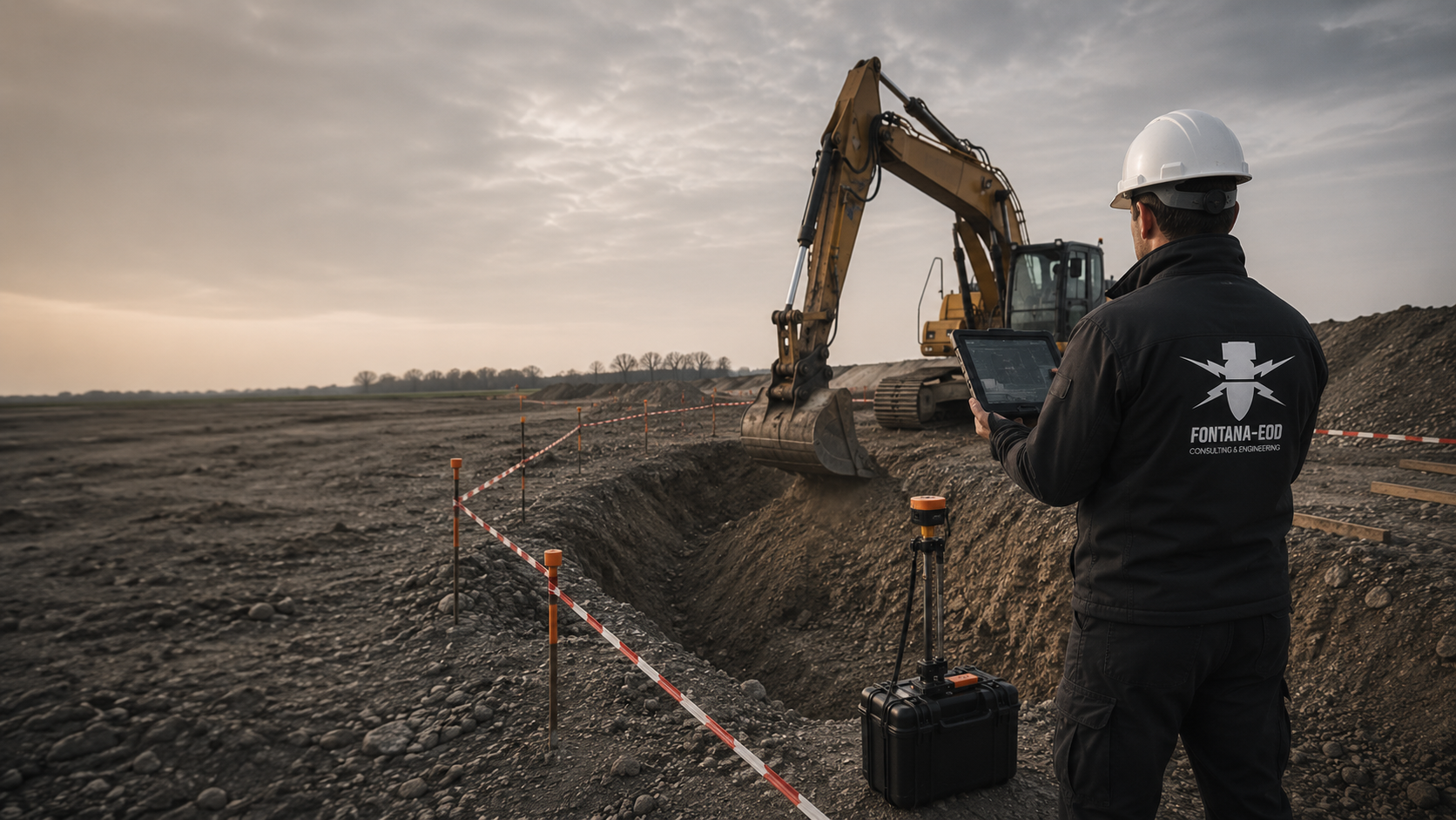
Field records document the work area, construction conditions, surveys, interruptions, observations and reporting procedures.
Supervise cable trench and excavation worksThe project records document exposure, assessment, responsibility and further measures with location, date and work status.
Provide a traceable handover of findings and work statusThe final report contains the initial situation, methods, data, findings, survey limitations and outstanding tasks.
Document installation records and handover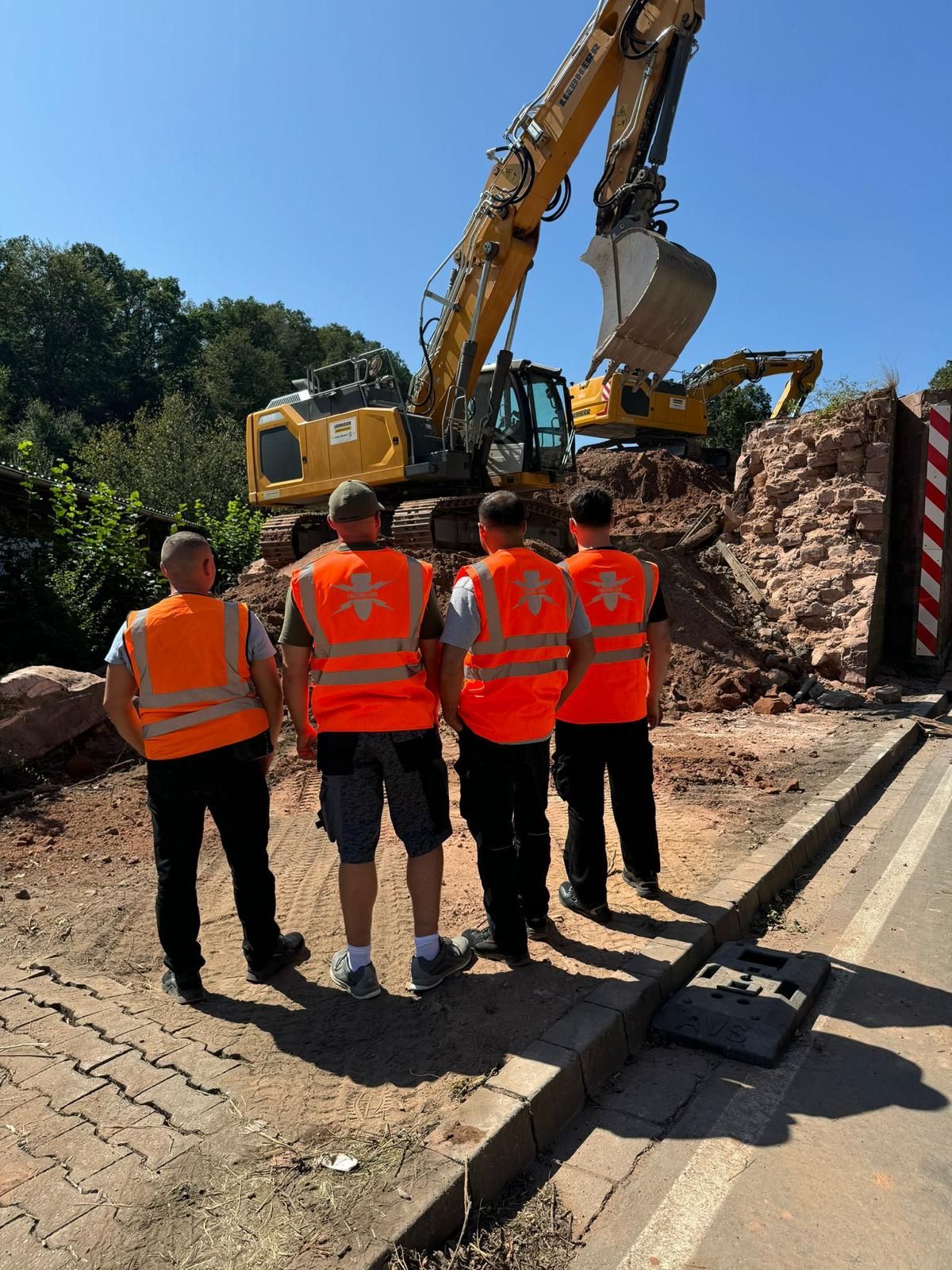
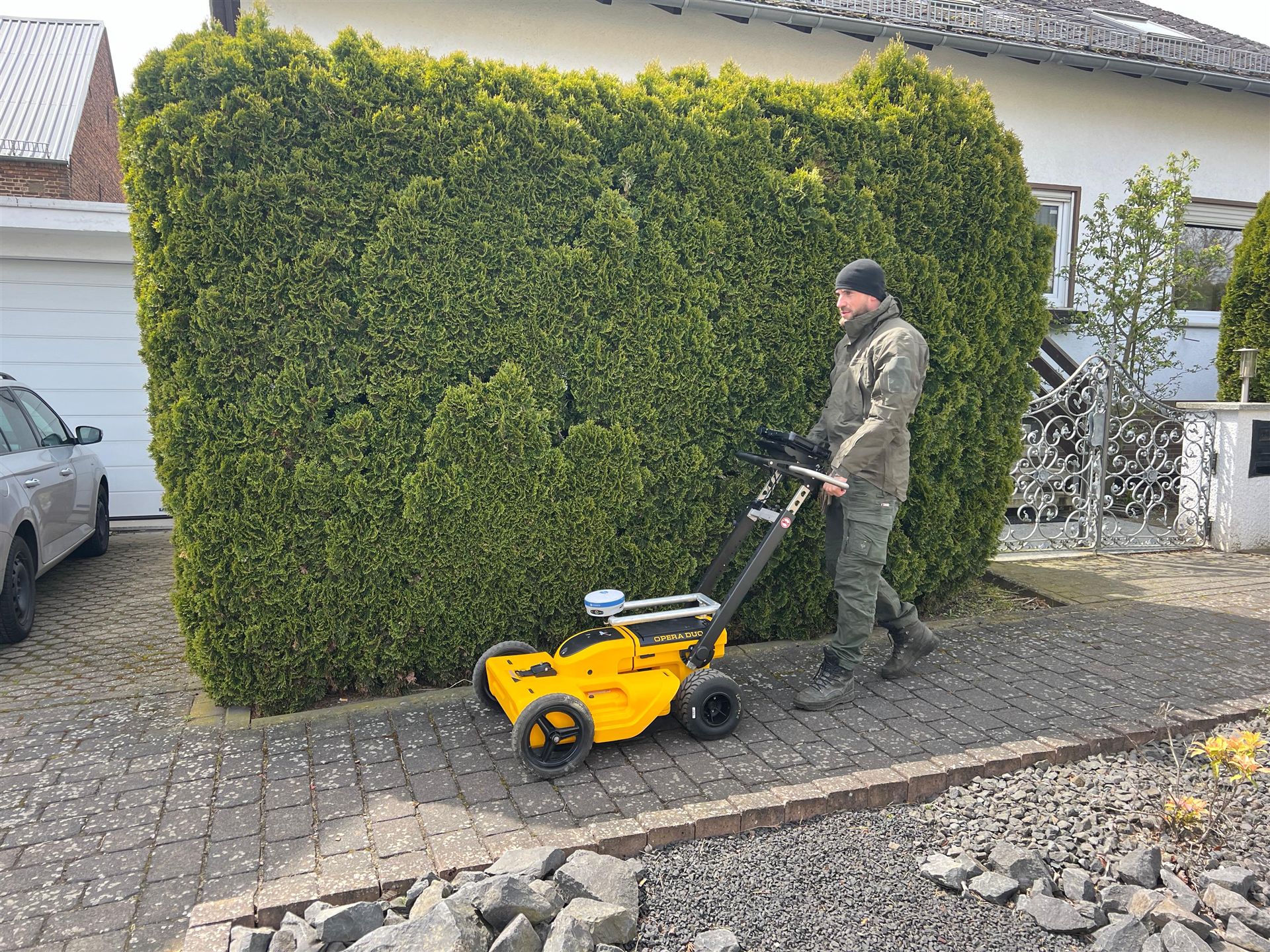
Historical hazard assessment, deep-ground surveys, excavation supervision, investigation of findings and documentation each address a distinct part of the project.
Selection depends on the next planning step, the specific installation area and the assessment needed before procurement or construction.
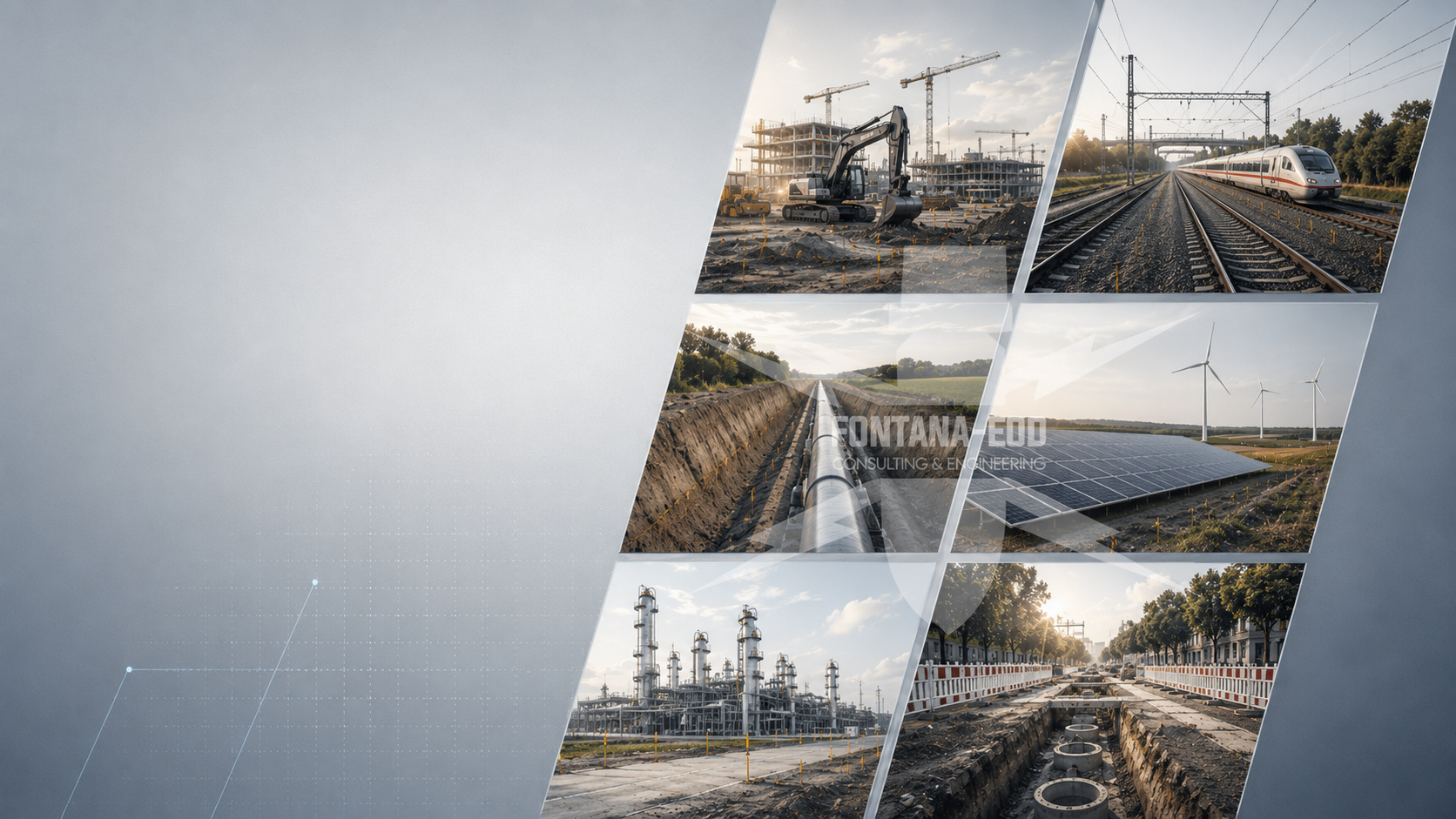
Plan ordnance assessments for transport, utility, energy and other infrastructure projects according to their ground interventions.
Have the project surroundings assessed by specialistsDistinguish utility corridors, crossings, foundations and installation areas by construction method and intervention depth.
Assess the energy project in its overall contextEvaluate historical indications and data gaps at the planned installation site.
Determine the historical suspected hazardPrepare surveys for deep foundations, masts, piles, shoring and borehole locations.
Assess deep interventionsEstablish the suitability and sequence of construction-phase ordnance surveying for remaining excavation areas.
Plan excavation supervision within the construction sequence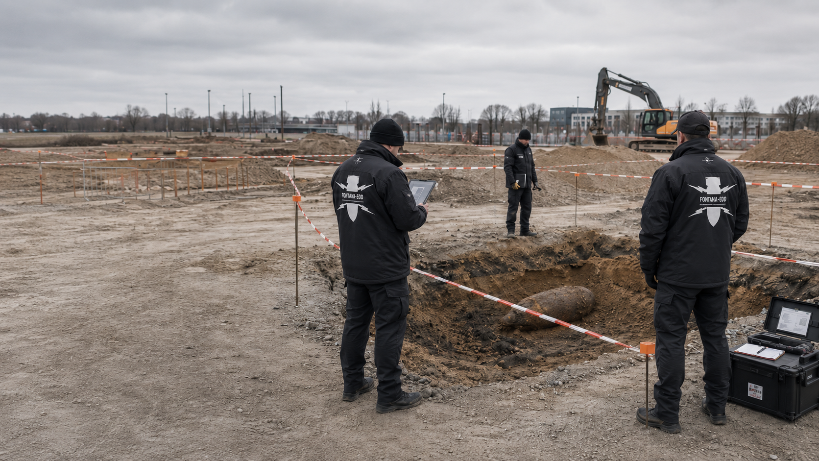
Coordinate recovery of confirmed ordnance with the permitted activities and local responsibilities.
Clarify the findings and recovery processPrepare the specification, data formats and section handovers for installation construction.
Prepare tendering and documentation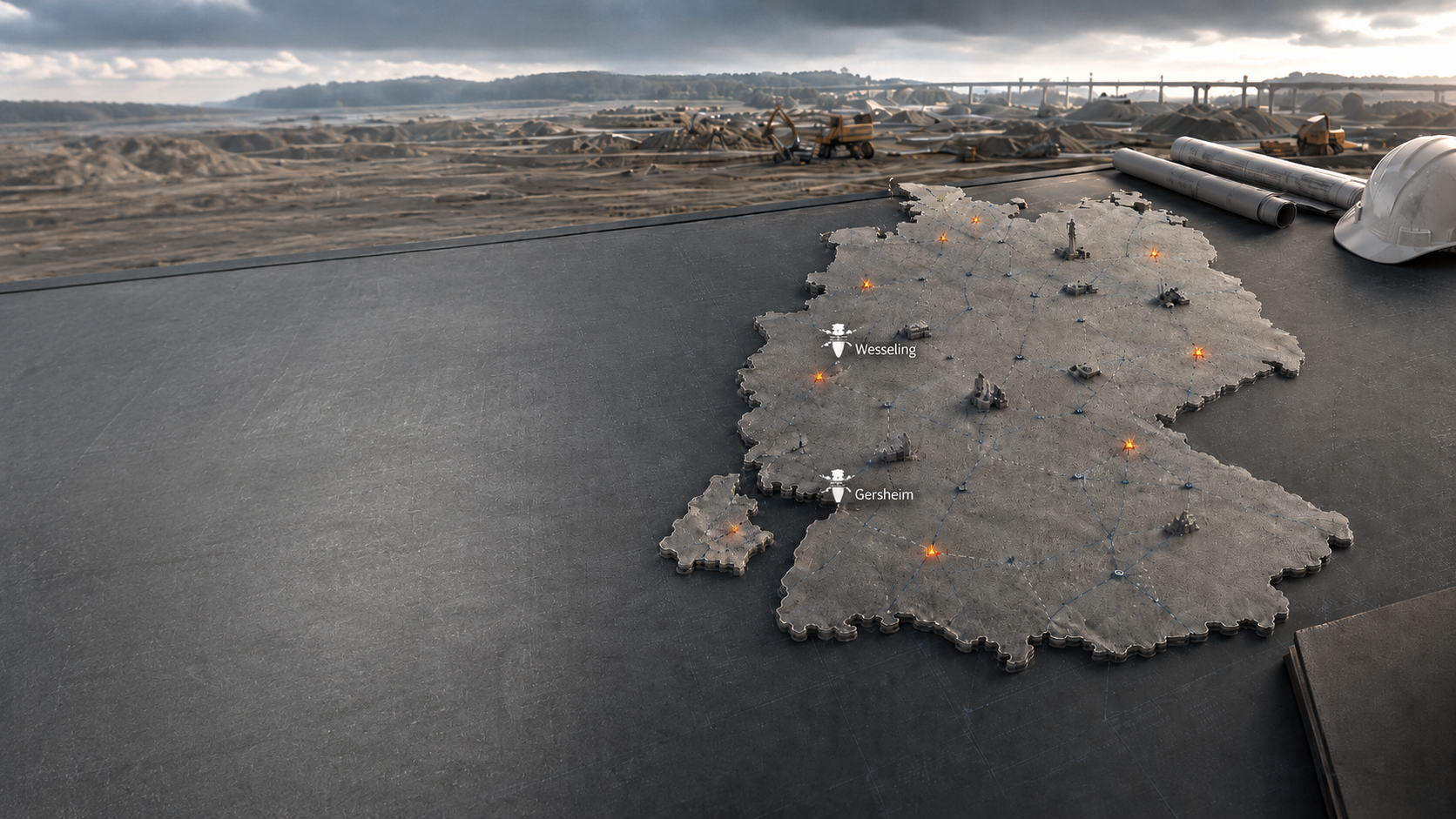
Clarify the project location and local responsibilities for planning, conditions and communication about finds.
Clarify regional responsibilitiesSubmit the installation plan, ground intervention depths and construction schedule for a project assessment.
Submit project recordsState the project location, installation designation and affected switchgear bays, transformer areas or cable sections. The site plan, foundation list and operational access plan must identify the same design revision. Existing requirements are assigned to the relevant volumes of ground affected.
A new transformer or a changed gantry may require different foundation dimensions and depths. Compare the current foundation geometry with the documented survey volume and mark areas extending beyond it.
Check evidence against the interventionEven smaller cable or earthing works may lie outside previously surveyed areas. Show their routes and planned depths on the installation plan so that the work does not focus solely on the large foundation areas.
Explore the technical principlesTechnical information
Utility routes, substations and energy installations place different demands on ordnance assessment. The brochure shows the design information needed and how investigation, construction sequence and documentation fit together.

Before each construction section, grid operators, designers and contractors need information on surveyed areas and outstanding tasks. The installation layout, ground intervention depth, construction stage and technical survey feasibility remain decisive.
The assessment should begin as soon as the site and main construction geometries are known. Before ground investigation, foundation excavation, cable trenches, piles, gantries and temporary heavy-load areas, the suspected hazards and specific volume of ground affected must be assessed.
The historical assessment substantiates and defines the limits of a possible suspicion, but does not detect objects currently in the ground. Where relevant indications exist, a technical assessment follows, related to the foundations, cable routes, buildings and other ground interventions in the installation layout.
Earthing conductors, steel structures, cables and technical installations can affect magnetic or electromagnetic surveys. Existing asset plans, construction conditions and accessible survey areas are therefore checked before deployment. Suitable supplementary methods and later survey access are assessed for areas that cannot be evaluated adequately.
Piles, masts, gantries, shoring and ground investigation boreholes may extend beyond the area covered by near-surface surveys. We then assess which method can cover the planned volume of ground down to the required depth. Coordinates, diameters, installation methods, ground conditions and technical interference are considered when selecting the method.
This depends on the project. Access, shutdowns, exclusion zones, electrical installations, survey interference and concurrent work are coordinated with the operator. Areas that cannot be accessed reliably in their current condition are assigned to a suitable later construction stage.
The documentation must include the task, design revision, installation and point references, methods, survey and working conditions, data, anomalies, findings, areas that cannot be assessed, limits of work and the technical follow-up decision for each construction section.
Key factors are the area, number and depth of foundation and borehole locations, cable routes, accessibility, ground and surface conditions, technical interference, operating conditions, required methods, data formats and the scope of project and final documentation.
Stop work in the affected area immediately. Do not touch, move or further expose the object. Leave the danger area and keep others away without putting yourself at risk. In Germany, notify the police immediately on 110; outside Germany, use the local emergency reporting procedure. The competent authorities determine the next steps. Then inform site management and those responsible for the installation.
An initial enquiry can be based on an early design revision. It should identify the site, installation layout, planned construction phases, main ground interventions and the next decision required.
For extensions, distinguishing existing installations, dismantling, modifications and new construction is particularly important. This allows assessment requirements to be related to work that actually involves ground intervention.
Incomplete or conflicting documents can be included. They show which design or existing asset information needs clarification before a reliable specification can be prepared.
Send the address, land parcel, site plan, coordinate system, switchgear bays, transformer locations, buildings and planned extension areas.
Mark existing installation areas, dismantling zones, construction sections and provisional layout options.
Where several design revisions exist, clearly identify the revision relevant to the assessment.
Describe foundations, piles, masts, gantries, cable trenches, drainage, excavations, boreholes and temporary heavy-load areas.
Specify target depths, diameters, slopes or shoring and the planned construction sequence.
Deep individual ground interventions should be listed with coordinates and target depths.
Include utility, earthing and existing asset plans, historical assessments, authority documents, previous survey reports and known findings. Information and conditions from authorities are included with their date, complete attachments and spatial scope.
State access conditions, shutdowns, exclusion zones, construction windows and concurrent trades.
Describe whether the result is needed for planning, tendering, site management or project records.
For an initial assessment, a site plan, brief project description, foundations and cable routes, maximum ground intervention depths, current construction conditions and existing hazard information are often sufficient.
FONTANA-EOD checks your documents to identify which surveys are required and what information is missing. For projects with several phases, work can be divided by construction section and decision deadline.
Areas, point quantities, depths, access, data formats and required documentation are then defined more precisely for reliable costing.
Installation area, switchgear bays, buildings, temporary areas and inaccessible zones.
Transformer foundations, masts, gantries, piles, boreholes and target depths.
Cables, earthing grid, steel structures, shutdowns, exclusion zones and construction windows.
Documents for planning, procurement, HSE, site management, the operator or project records.
Whether historical aerial photograph analysis, explosive ordnance surveying, surface surveying using GPR, magnetometry or TDEM, deep-ground surveys, downhole surveys, excavation supervision, area clearance or ordnance recovery is needed depends on the location, ground disturbance, depth, ground and existing documents. An early ordnance assessment provides clarity for tendering, programming, occupational safety and construction.
FONTANA-EOD combines its Section 7 SprengG licence, specialists holding Section 20 SprengG certificates of competence, suitable survey and clearance methods, and traceable documentation. Send the site plan, depth of ground disturbance, construction phase and existing documents for an initial technical assessment.


