Project pathway
The quickest route to the right decision.
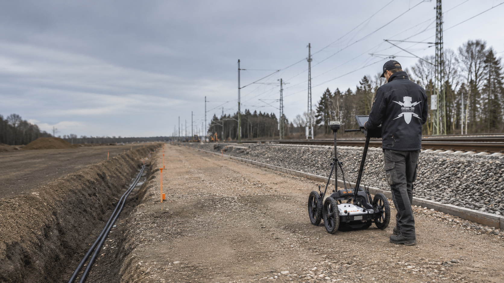
For cable works, station redevelopment and other ground disturbance around railway infrastructure, designers and construction supervisors need to establish what ground-penetrating radar can reveal about the working area. Rails, sleepers, cables, foundations and technical installations affect radar profiles. Send FONTANA-EOD the section plan, planned depths and existing-structure information so that we can assess the survey objective, profile layout and scope for interpretation. Areas that cannot be investigated adequately require a suitable additional method.
Identify the working area and required findings.
Account for track superstructure, utilities and buried installations.
Record the survey data, limitations and next steps.
Ground-penetrating radar can record layer boundaries, utilities and other subsurface structures in the track environment. Whether the data describe the planned ground disturbance adequately depends on the ground, infrastructure and survey geometry.
The method does not directly identify unexploded ordnance. Unresolved areas require a documented assessment and, where necessary, additional investigation.
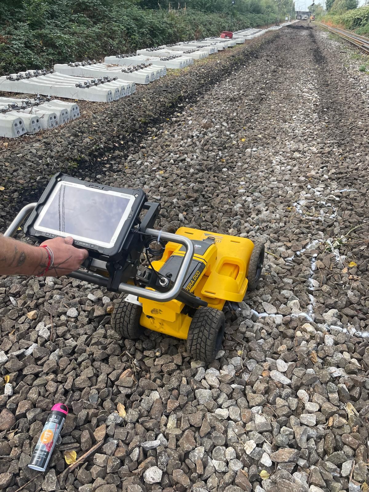
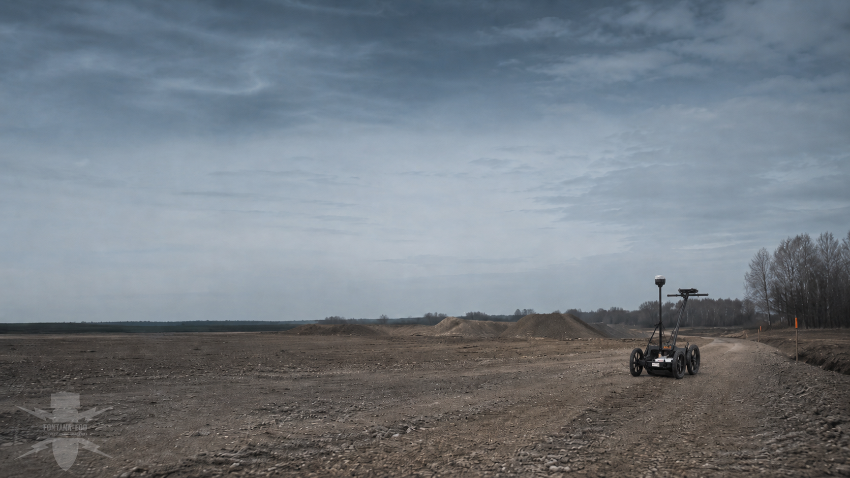
An area of 1,432 m² was surveyed using the IDS Opera Duo 250/700 MHz. The case study presents original radargrams and 3D survey-data views, explains the interpretation down to 0.80 m and describes the limitations where signals overlap. View project details.
The same survey equipment can address very different questions in railway construction. The actual working area and the subsurface structures that need to be distinguished for design or construction determine the task.
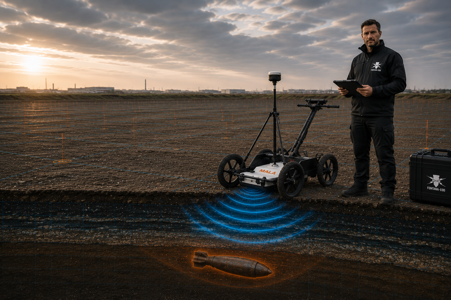
Rails, sleepers, fixings, ballast and cable installations produce recurring reflections. For interpretation related to explosive ordnance, these known structures must be distinguished from local signatures that remain unexplained.
Survey direction, antenna position and profile spacing are selected to cover the relevant working area as fully as possible despite structural constraints.
Assess surface surveying for track renewal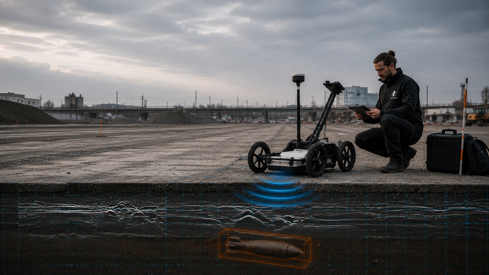
GPR can add information about utilities and structures when cable trenches, chambers or signal foundations are being prepared. Known utilities and buried installations are included in the spatial reference before interpretation begins.
The planned ground disturbance remains the deciding factor. Profile layout and interpretation must cover the actual trench alignment, width and depth.
Assess GPR for the cable corridor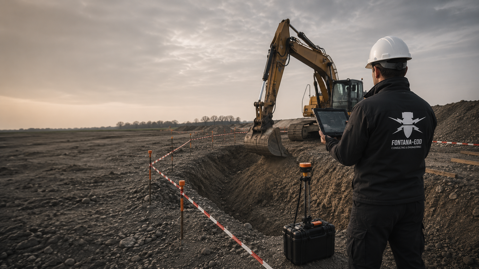
Platform surfacing, slabs, foundations, utilities and buried installations may allow a structural radar survey but can also produce complex multiple reflections. Consistent antenna movement and a reliable position reference are particularly important.
Inaccessible edges, above-ground installations and structural connections are identified separately.
Assess specialist supervision for station alterationsAsphalt, paving, fill, existing foundations and dense utility networks create changing survey conditions. Suitability may vary considerably within one site.
Areas are therefore planned separately according to their surface, interference environment and construction task. Findings remain specific to each section.
Assess surface surveying for operational areas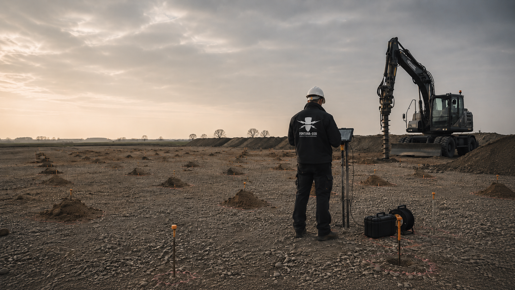
Mast locations, earthing systems, foundations and technical installations can affect the radar response as much as the natural ground. GPR may provide additional structural information here, but it does not replace a depth-specific investigation of planned foundations.
For each location, the assessment defines what can be established near the surface and where a borehole survey is required.
Assess deep-ground surveying for foundation pointsReinforcement, existing foundations, large structural elements and varying fill produce strong reflections and screening. The survey is limited to accessible working areas and a clearly defined project question.
Additional investigation methods are planned separately for piers, abutments, retaining-wall alignments and deep foundations.
Assess deep-ground surveying at foundationsRoad construction, track, cables, drainage and signalling equipment meet within a confined area. A radar profile can show known and unknown structures, but its position must be clearly referenced on both sides of the interface.
The investigation area is aligned with the crossing axis, construction method and planned depth range.
Assess GPR at crossings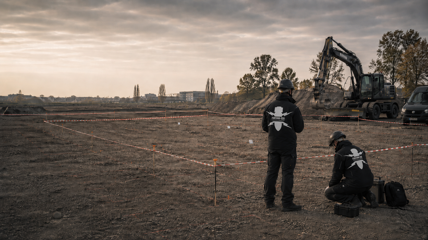
Large track yards and former operational areas often contain heterogeneous fill, numerous buried installations and different surfaces. GPR is suitable only for clearly defined tasks and sections where the data can be interpreted.
Survey planning brings together historically suspected areas, the current track geometry and the specific redevelopment areas.
Assess area clearance around tracksFirst, the team clarifies which structures are to be investigated and where. The equipment settings and survey scope can then be planned.
Before surveying, the team must establish whether the aim is to assess structures, voids, utility routes, changes in layers or anomalies relevant to explosive ordnance within the planned ground disturbance.
A general request for “GPR” does not define a survey objective. The required findings determine the grid, profile layout, antenna configuration and interpretation.
Agree the survey objective for the sectionSurvey profiles need a clear reference to the railway line, track, kilometre or chainage, coordinate system and level datum. Without this link, anomalies cannot reliably be related to a cable trench, foundation or excavation.
Before fieldwork, drawings and site conditions are checked against the alignments, reference points and construction stage.
Define position and data referencesBallast, asphalt, paving, concrete, platform surfacing, steps and uneven lineside paths affect antenna movement and the comparability of neighbouring profiles.
The plan identifies areas accessible to a survey vehicle or on foot, locations where antenna clearance or orientation changes, and sections that require separate assessment.
Assess suitability for the surface conditionsRails, sleeper fixings, cables, cable troughs, foundations, reinforcement, chambers and drainage each produce their own signatures. Existing-structure information supports interpretation but does not replace the survey.
Unexplained reflections are prioritised by the specialists only after comparison with these known structures.
Compile the railway constraintsResolution and achievable depth are technically linked. Profile spacing, survey direction, antenna frequency, time window and survey speed are matched to the target size and ground conditions.
Check profiles and suitable test areas help establish whether signatures can be reproduced and located reliably.
Develop the survey planBefore fieldwork, the team should establish how to address areas that cannot be interpreted, strong reflections and relevant anomalies. Depending on the project, additional magnetometry, TDEM, deep surveys, exposure or excavation supervision may be appropriate.
The report then identifies the additional investigations required for these areas.
Define additional services for outstanding areasGPR suitability can change within a few metres. Areas with favourable, limited or unreliable survey conditions are therefore documented separately.
Within the DB railway and track environment, rails, sleepers, ballast, cables, reinforcement, foundations, moisture and changing fill create complex radar profiles. Suitability is therefore assessed for each section against the survey objective, surface, profile layout, required depth and known infrastructure.
Survey conditions: The antenna can be moved at a largely consistent clearance and speed, and the ground does not strongly attenuate the signal.
Effect: Profiles can be compared readily, and spatial patterns can be traced across several survey lines.
Assessment: The findings remain limited by profile spacing, target size and the depth range actually surveyed.
Survey conditions: Changes in material, grain structure, voids and moisture produce numerous reflections or attenuation.
Effect: Structural patterns may be clearly visible while individual local signatures are lost in background noise.
Assessment: Knowledge of existing infrastructure, cross-profiles and parameters selected for each section become more important.
Survey conditions: Metal components reflect a large proportion of radar energy and may screen the ground beneath them.
Effect: Known infrastructure dominates the radar image. Complete findings beneath or immediately beside the structure may not be possible.
Assessment: Profile layout, clearance and additional methods are planned for each section.
Survey conditions: High electrical conductivity attenuates electromagnetic waves and reduces the usable depth range.
Effect: Deeper structures may appear weakly or may no longer be interpretable, even where useful information is still available near the surface.
Assessment: Field trials, frequency selection and an alternative follow-up method are considered at an early stage.
Survey conditions: Reinforcement, foundations and slabs generate strong reflections in regular patterns.
Effect: The ground beneath may be partly screened, with known structural geometry dominating the image.
Assessment: Interpretation concentrates on accessible peripheral areas. Borehole surveying provides additional investigation for deeper ground disturbance.
Survey conditions: Railway operations, installations, safety clearances or missing vehicle and pedestrian access prevent complete profile coverage.
Effect: The dataset contains spatial gaps. Interpolation must not be used to present these as investigated areas.
Assessment: Outstanding areas are identified on the plan. The assessment considers whether later exposure, another investigation method or explosive ordnance surveying during construction is suitable for the planned ground disturbance.
Antenna configuration, profile geometry and data quality form an interconnected survey system. Changes during acquisition are documented for each section.
The size, shape, expected position and orientation of the structure being sought determine the required spatial resolution. The survey task and construction project must therefore identify the working area and object size relevant to the subsequent decision.
Higher frequencies can resolve finer structures but are usually attenuated more strongly in the ground. Under suitable conditions, lower frequencies may reach greater depths but produce coarser images. The selection is justified for the particular project.
Longitudinal profiles help trace recurring structures along the route. Cross-profiles help assess their extent across the track, lineside path or cable corridor. Spacing must suit the target size and available working area.
Antenna clearance, orientation and coupling affect signal shape and comparability. Ballast, steps, cable troughs, platform edges and uneven surfaces are recorded in the field notes and considered during interpretation.
Each survey reading needs a reliable position reference. Profile start and end, survey direction, track, kilometre or chainage and prominent structures are recorded so that anomalies can be located again on drawings and on site.
Raw data are checked in the field for dropouts, saturation, changes in coupling and positioning errors. Repeat and cross-profiles help distinguish local signatures from acquisition errors and recurring structural elements.
A GPR report must explain how the project question was translated into accurately positioned survey data and how those data support conclusions with clearly stated limits.
The brief describes the planned ground disturbance, the section to be investigated and the required findings. It distinguishes explosive ordnance-related questions from utility location, structural investigation and general ground investigation.
This distinction guides the survey plan, interpretation and report.
Survey lines, travel or walking direction, chainage, reference points, obstacles and unsurveyed areas are documented with geographical references.
The plan also shows how the survey area relates to the cable trench, foundation, excavation or other ground disturbance.
Antenna configuration, frequency range, time window, survey-point and profile spacing, acquisition speed and relevant filter and gain settings are recorded clearly.
Changes between sections receive a separate identifier.
Original survey data remain distinguishable from processed displays. Key processing steps are documented so that radargrams and area plots can be traced back to the dataset.
Interpretation and visualisation must not overstate the information actually present.
Anomalies are compared with parallel and cross-profiles, known utilities, track structures, existing-structure drawings and, where appropriate, test areas.
The assessment distinguishes explainable infrastructure signatures, ambiguous signatures and areas requiring further investigation.
The report identifies the surveyed area, assessed depth range, data quality, screening and areas that could not be interpreted. Suitable follow-up measures are described for relevant anomalies and outstanding areas.
The conclusions remain limited to the documented survey and working area.
Survey lines, position information, raw data and interpretation are checked against each other. The areas actually investigated must remain clearly identifiable.
If suspected targets are subsequently exposed or areas cleared, the findings and clearance records for that work are added. They refer to the relevant survey profiles, location identifiers and the same drawing revision so that the client and site management can identify the follow-up measures.
The railway line, track, kilometre or chainage, structure, drawing revision and internal section identifier are consistent across the brief, profile register, maps and report.
Planned and recorded survey lines are compared. Dropouts, obstacles, safety clearances and inaccessible areas remain identified by location.
Processing steps, parameters and displays are documented so that the specialist interpretation can be traced back to the raw data.
Rails, sleepers, cables, foundations, chambers, drainage and other known installations provide a basis for checking recurring signatures or signatures at fixed locations.
GPR initially measures travel time. Conversion to depth is described using the assumed or calibrated propagation velocity. Changes in material and moisture remain identified as sources of uncertainty.
The assessment identifies the working area covered, relevant anomalies, areas subject to technical limitations and the further work required for the planned ground disturbance.
The sequence is adapted to access, construction phase and track possession. Data quality and clear position references are checked at every step.
The railway line, track, survey area, construction task, depth of disturbance and required findings are defined on a current site plan.
Historical assessments, utility plans, track and structural information and earlier surveys are assessed against the proposed section.
The surface, access, existing track and installations, moisture, sources of interference, safety clearances and possible profile routes are checked.
Frequency, profile spacing, survey direction, positioning, check profiles and recording parameters are selected according to target size and the survey environment.
Profiles are recorded with clear section and direction identifiers. Deviations, obstacles and changes in coupling are documented in the field.
Dropouts, saturation, positioning errors and sections that cannot be compared are identified before fieldwork is completed.
Known structures, recurring patterns, local anomalies and areas that cannot be interpreted are compared across several profiles and against the drawings.
The report, profile register, maps, data quality, limitations and recommended further investigations are related to the planned ground disturbance.
GPR data are indirect measurements. A reliable assessment distinguishes the physical signal, known infrastructure, technical uncertainty and the explosive ordnance-related project question.
A radargram shows received signal energy against travel time along a profile. Continuous layers, discrete objects and technical installations generate different patterns. The display does not directly reproduce the visible outline of an object.
Several longitudinal and cross-profiles, a clear position reference and comparison with existing-structure information improve the spatial interpretation of signatures. The number and spacing of profiles depend on target size, the construction task and survey conditions. Interpretation assesses whether an anomaly is repeatable, can be explained by a known structure or needs further investigation for the planned ground disturbance.
The specialist conclusions remain limited by the survey conditions and the working area covered. Data gaps, screening and uncertain depth models are not treated as investigated areas.
Radar waves are reflected where the electrical properties of materials change. Layer boundaries, utilities, voids, foundations and other buried installations can therefore produce visible signatures.
A strong reflection initially indicates a contrast, not automatically the type of object.
Small or point-like structures can generate curved patterns in a two-dimensional radargram. Their shape and apex are assessed using neighbouring profiles and suitable interpretation methods.
The displayed pattern does not directly reproduce the actual outline of the object.
The system records the travel time of transmitted and received signals. Depth estimates use an assumed propagation velocity or one calibrated against suitable information.
Moisture and changes in material may alter propagation velocity. Depth estimates are therefore reported with appropriate uncertainty.
Conductive soils attenuate radar energy. Metal surfaces can reflect strongly and screen the ground beneath. In the railway environment, this includes rails, reinforcement and extensive technical installations.
These areas are documented as technical limitations. Interpretation must not artificially fill the gaps.
Longitudinal profiles show how a signature develops along the route. Cross-profiles show its extent across the track, lineside path or cable corridor. Comparison helps distinguish linear existing infrastructure from localised anomalies.
A consistent position and direction reference is essential.
A signature only becomes relevant to the project when its position and depth are considered alongside the planned construction task. An anomaly at a foundation location is treated differently from a similar signature outside the working area.
The conclusions therefore always relate to the specific ground disturbance.

Compare existing aerial imagery assessments and earlier investigations with the planned survey corridor. The GPR brief needs a specific question about the area of ground disturbance. Recording an area alone does not define the required investigation objective.
Assess the basis for suspicionIf interpretable GPR data do not reach the planned ground disturbance, the remaining area requires separate assessment. The suitability of a deep survey depends on the suspected risk, geometry and actual access.
Assess depth-related investigationThe methods respond to different subsurface properties. Selection depends on the target, the geometry of the ground disturbance and the actual survey conditions.
If the data are insufficient to assess the planned ground disturbance, the affected areas are documented as unresolved. Depending on the task, follow-up work may include magnetometry, TDEM, deep or borehole surveys, exposure or excavation supervision.
Technical contribution: Records reflections from layers, buried installations and local material contrasts. It can add structural information in areas with strong magnetic interference.
Key limitation: Signatures are often ambiguous. Attenuation, screening and known structures limit the findings. Automatic identification of unexploded ordnance is not possible.
Assess the survey principle and limitationsTechnical contribution: Detects changes in the Earth's magnetic field caused by ferromagnetic objects. In areas with sufficiently low interference, it is suitable for area-wide anomaly mapping.
Key limitation: Rails, fences, vehicles, reinforcement and metal-rich fill can strongly mask the survey signals around railway infrastructure.
Assess conditions for magnetic surveyingTechnical contribution: Electromagnetically excites conductive objects and assesses their time-dependent response. In suitable areas, it can complement metal detection.
Key limitation: Rails, utilities, extensive metal components and varying survey height can dominate or distort the signals.
Assess TDEM for the sectionTechnical contribution: Provides evidence for suspected areas, prioritises route sections and relates historical events and locations to the technical investigation.
Key limitation: It does not show the objects actually present in the ground today and does not replace a field investigation.
Clarify historical suspicion indicatorsTechnical contribution: Investigates defined locations and depth ranges for masts, piles, signals, retaining-wall alignments and other deep ground disturbance.
Key limitation: The findings apply to the planned investigation geometry and do not automatically cover surrounding areas.
Plan deep investigation for foundationsTechnical contribution: Combines investigation and assessment of each excavation layer with subsequent controlled soil removal and additional visual checks. The steps are repeated down to the agreed excavation base. Anomalies trigger the defined hold points and reporting procedures.
Key limitation: It covers only the excavation layers supervised and does not provide area-wide findings for ground that was not investigated.
Supervise excavation in outstanding areasSurvey lines, positioning, data checks and interpretation must suit the planned investigation.
FONTANA-EOD checks the acquired data, interprets the radar profiles and describes the technical limitations of each section investigated.
Before acquisition, the working area, target size and known installations are related to the same drawing revision. Interpretation can then distinguish recurring track structures from local signatures that remain unexplained.
Changes in coupling, obstacles, dropouts and deviations are documented in the field. Where quality problems are apparent, the team assesses whether profiles need to be repeated or parameters adjusted for the next section.
The report describes anomalous signatures, screening and unresolved areas. It explains the further investigations required for the planned ground disturbance.
The target, construction task, area of ground disturbance and required findings are defined before the equipment is configured.
Surface conditions, materials, moisture and sources of interference are not assumed to be uniform along the whole route.
Profile layout, antenna position, positioning and acquisition quality are monitored in the field.
The assessment considers known infrastructure, cross-profiles, recurring patterns and technical limitations.
Unsurveyed, screened or unreliably interpretable areas are clearly identified on the plan.
The conclusions identify the further investigation or measures during construction required for the planned ground disturbance.
Ballast removal, utility removal and demolition of structural elements may change survey conditions. The required investigation, procedure and protective measures are defined before these works. Newly accessible areas then receive the additional investigation needed for the further work planned there.
The report must distinguish useful survey findings, areas with limited results and unresolved areas by location. Site management needs this information alongside the current ground-disturbance plan before preparing the next stage of work.
A GPR service involves design, railway operations, geophysical interpretation and, where necessary, the authorities responsible for hazard response. Clear responsibilities prevent design changes or relevant findings from being lost between the parties.
Defines the construction task, survey area, required findings, drawing revision and programme. Provides existing-structure, utility, UXO and operator information and decides on follow-up measures.
Translates the proposed works into specific tracks, cable routes, foundations, depths and construction stages. This information determines whether GPR is suitable and which working area needs to be assessed.
Arrange access, track possessions, isolations, working limits and safe movement within railway areas. Changes are communicated to the field team and construction supervisors before surveying starts.
Assesses survey conditions, develops the survey plan, acquires and interprets the data, and documents the limitations and suitable follow-up measures.
Checks the drawing revision, actual work, unsurveyed areas and handovers. Ensures that GPR findings are not carried over to changed ground disturbance without reassessment.
In Germany, the responsibilities of explosive ordnance disposal services and local authorities depend on the federal state, project location and circumstances of a find. The relevant contact for suspected explosive ordnance or a find is identified before the project work.
Public-order authorities and building control may be involved depending on local procedures and the construction task. Existing requirements are assigned to the actual site and working area. Commercial specialist services, operational work authorisation and authority decisions on finds each have their own contact and reporting arrangements.
For GPR surveys used in explosive ordnance investigation, the required authorisation, competence and occupational safety measures depend on the activities commissioned. Surveying, interpretation and any subsequent exposure are planned with their respective responsibilities. Railway access and safety arrangements are also included in work preparation.
In Germany, § 7 SprengG concerns the commercial authorisation for activities requiring authorisation; § 20 SprengG concerns the certificate of competence of responsible persons. Under § 1b SprengG, searching for found munitions also counts as handling them. The requirements applicable to the project depend on the activity actually commissioned.
DGUV Information 201-027 supports risk assessment and protective measures for explosive ordnance clearance work. The Baufachliche Richtlinien Kampfmittelräumung set requirements for investigation, quality and documentation within their defined federal scope. Their application to the particular project is clarified separately. Operator and project-specific requirements for access, track possessions and railway safety also apply.
If an unexpected suspected item is found, surveying or construction work stops. Do not touch or move it. Leave the immediate area and warn others without putting yourself at risk. In Germany, notify the police immediately on 110. Outside Germany, follow the local emergency reporting procedure.
The First Ordinance to the German Explosives Act (1. SprengV) includes requirements for specialist competence and officially recognised training courses. The qualifications required for GPR surveying and any subsequent work are determined by the actual commission.
DGUV Rule 113-003 concerns dismantling or destroying explosives or corresponding articles and also covers the disposal of found ammunition. Its applicability is assessed for relevant follow-up activities. Surveying, interpretation and work on finds are not treated as the same service.
Acquisition, positioning, data checks and interpretation require appropriately qualified personnel and documented working procedures.
Drilling, exposure, clearance and recovery are arranged within the authorisations, qualifications and responsibilities required for those activities.
Access, protective arrangements, isolations, working limits and communication are defined before fieldwork begins.
Everyone involved must know the hold point, protective arrangements, contacts and local reporting procedure.
The survey objective, section, access, known installations and data requirements are checked.
Deviations, data-quality problems and inaccessible areas are documented as they arise.
Follow-up measures are defined only for areas justified by their location and the technical findings.
Survey profiles, depth estimates and specialist interpretation are related to the same working area. The report distinguishes identifiable structures, ambiguous signatures and areas with inadequate coverage and compares them with the planned ground disturbance.
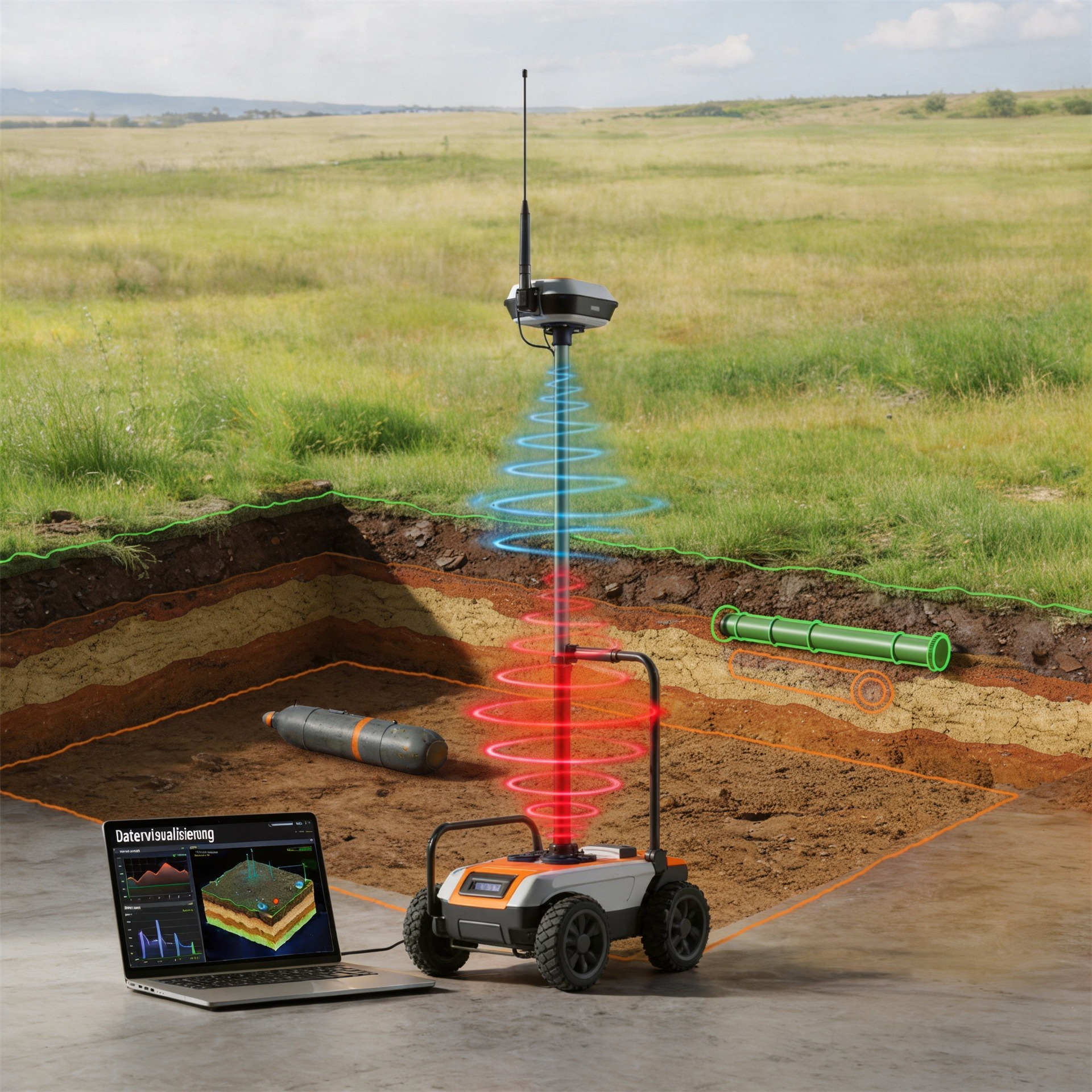
A GPR dataset contains many position-referenced individual traces along defined profiles. A planned arrangement of survey lines is needed to interpret an area or corridor.
In a railway project, profile direction and chainage are related to the track, cable route, structure and planned ground disturbance.
Explore survey geometry and data quality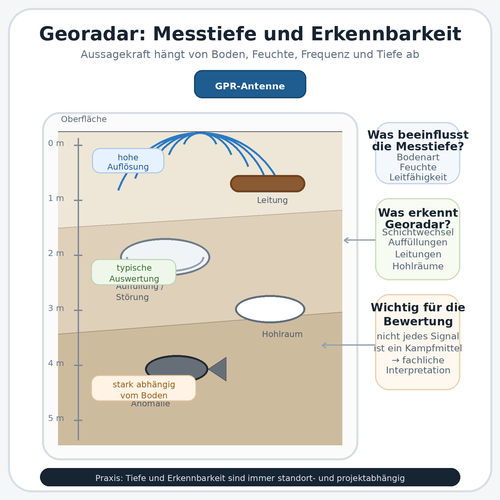
Greater theoretical penetration does not automatically mean that small or unfavourably oriented structures can still be distinguished reliably.
Service planning therefore specifies not only the design depth but also target size, required data quality and the survey and positioning uncertainties to be considered in the assessment.
Clarify survey depth and detectability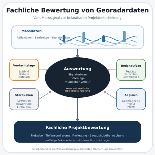
Filters and visualisation help make signatures visible but do not replace specialist interpretation. Recurring track structures, utilities and local anomalies need to be checked across several profiles.
The results distinguish a technical explanation, an unresolved signature and the recommended follow-up measure.
Interpret radar profiles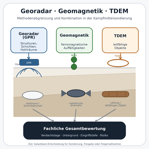
GPR provides reflection data related to structures, magnetometry records magnetic anomalies, and TDEM measures electromagnetic responses from conductive objects. No method covers every object and interference condition.
Methods are combined only where this genuinely improves assessment of the intended working area.
Compare supplementary survey methods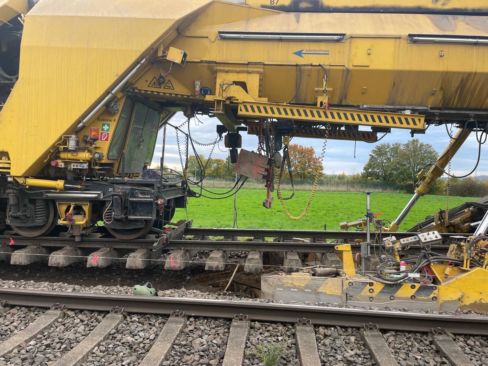
Depending on the unresolved project question, the priority may be the construction task, survey method, an alternative survey, deeper ground, an outstanding area or the required records.
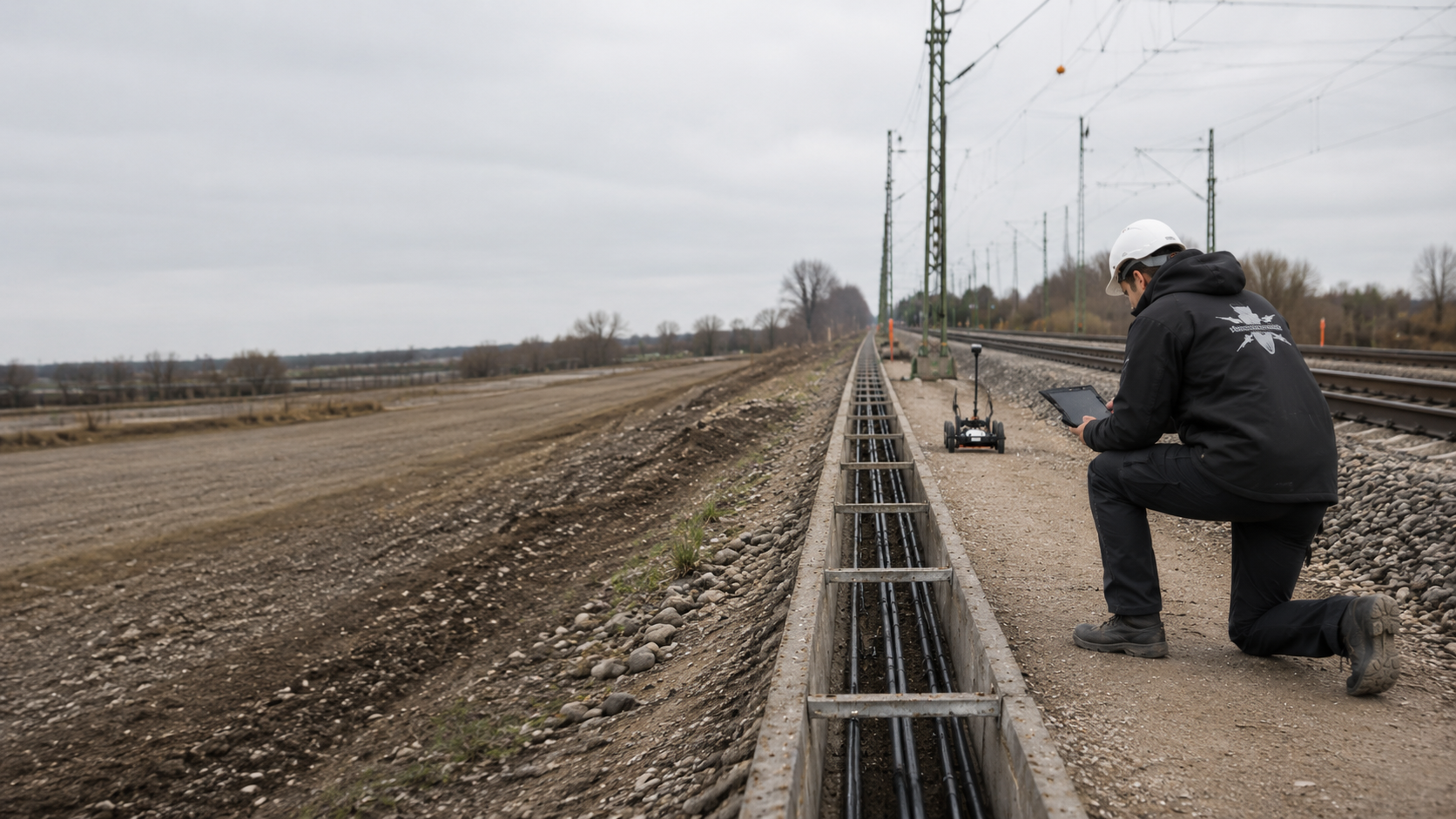
Distinguish track works, cable works, traction power, platforms, bridges, operational areas and excavation according to their particular construction tasks.
Select the railway project by working areaAssess the survey principle, dependence on ground conditions, antenna configuration, data processing and general limitations.
Assess the GPR methodCompare GPR, magnetometry and TDEM against the target, interference environment and required findings.
Compare surface survey methodsPrepare the survey area, existing-utility information, signal foundations, crossings and construction phases for narrow railway infrastructure corridors.
Assess GPR for the cable corridorInvestigate mast, pile, signal and retaining-wall locations with their own investigation geometry and documented depth range.
Plan deep investigation for foundationsSupervise excavation in areas that could not be fully surveyed, using defined layers, hold points and reporting procedures.
Agree supervision for outstanding areasEstablish suspected sections, previous uses and data gaps as the basis for the survey area and its priorities.
Establish the historical basis for suspicion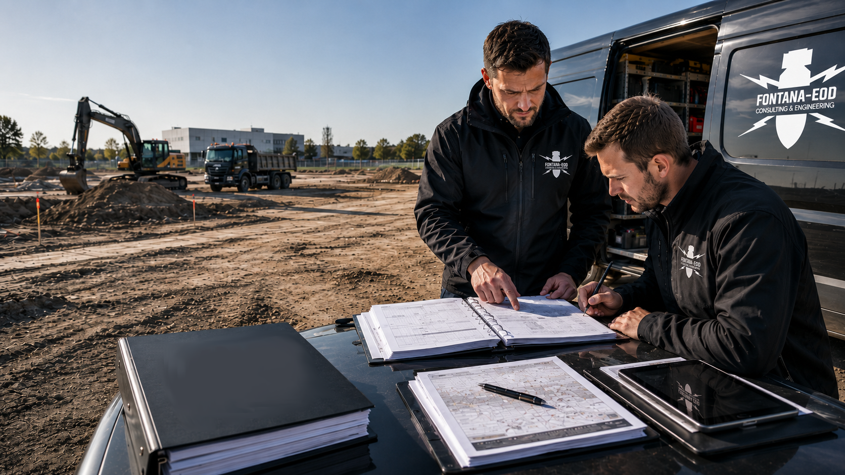
Organise the profile register, raw data, interpretation, quality checks, maps and follow-up decisions for tendering and the project file.
Define the data and documentation scope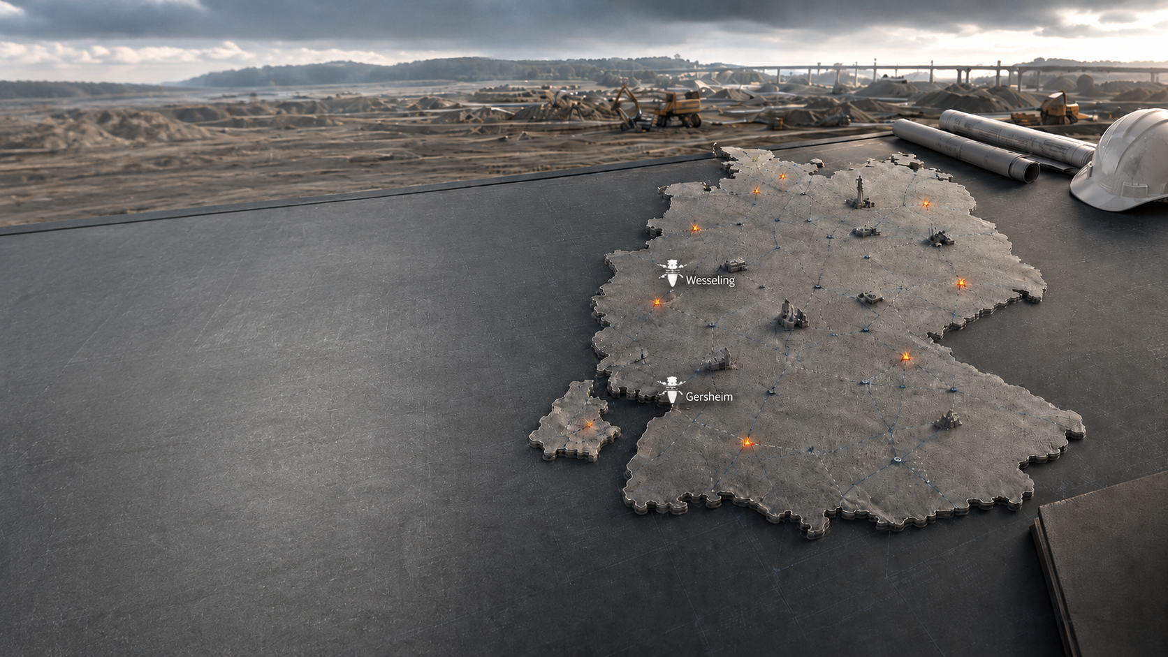
Provide the project location, railway line, track and chainage. Survey profiles, drawing revision and level reference must relate to the same working section. Include existing official or operational requirements with their actual geographical scope.
A stated survey depth is only meaningful alongside the documented ground and data conditions. Compare the interpretable range with the proposed excavation, borehole or utility level. Greater construction depth requires renewed specialist assessment.
Check evidence against the interventionAn anomalous radar signal is initially a physical observation. The specialist assessment considers known installations and additional information. A single signature does not establish a particular type of unexploded ordnance or provide general clearance.
Explore the technical principlesTechnical information
The brochure shows how FONTANA-EOD combines historical investigation, specialist planning, surveying and construction supervision in infrastructure projects. It explains trackside constraints, method selection and limitations, and result documentation.
The ground, track superstructure, profile layout and data quality determine what GPR can establish. Areas with inadequate coverage remain marked for further investigation.
GPR is suitable where reflections at material and structural boundaries can address the investigation objective and where the surface, ground and profile layout allow interpretable data to be acquired. In the track environment, suitability is assessed section by section because rails, ballast, utilities, foundations, moisture and operational access can significantly affect data quality.
Suitability should be clarified before tendering and the fieldwork date wherever possible. The survey objective, construction phase and available access must be defined before the profile network and acquisition scope are commissioned.
GPR measures electromagnetic reflections and records contrasts in the ground. An anomalous signature may come from utilities, stones, foundations, voids, changes in material or other objects. Explosive ordnance-related assessment therefore considers position, shape, repeatability, known infrastructure, the basis for suspicion and the planned ground disturbance.
The required information includes a current site plan, railway line and track, kilometre or chainage, survey area, construction task, depth of ground disturbance, track and surface information, utility and existing-structure drawings, historical UXO records, and details of access, track possessions and safety arrangements. Earlier survey or ground investigation data help assess suitability.
Existing official and operational requirements are supplied with all attachments and the responsible contact. Local coordination and reporting procedures are clarified before fieldwork.
Rails, fixings, cables, cable troughs, reinforcement and foundations produce strong or recurring reflections. Metal structures may also screen the ground beneath. Profile layout and interpretation are therefore adapted to known structures, while areas where reliable results cannot be obtained are identified by location.
This depends on the ground, antenna configuration, target size and achievable data quality. Deep ground disturbance often requires a separate deep or borehole survey because near-surface GPR cannot reliably cover the entire foundation volume. The two methods can be coordinated within one project.
The report describes the survey objective, section, profiles, positioning, equipment and acquisition parameters, surface conditions, sources of interference, data processing, relevant signatures, areas that could not be interpreted and the assessed depth range. Maps and the profile register relate the findings to the planned ground disturbance and identify required follow-up measures.
Excavation supervision may be needed where track superstructure, utilities, installations, screening or lack of access prevent an adequate preliminary survey. It is limited to defined excavation layers and working sections and requires agreed hold points, reporting procedures and records.
This includes technical investigation and assessment of each working layer before soil is removed. Visual checks supplement the investigation. If an unexpected suspected item is found, work stops. Do not touch or move it. Leave the immediate area and warn others without putting yourself at risk. In Germany, notify the police on 110; outside Germany, follow the local emergency reporting procedure. The competent authorities determine the next steps.
Key factors include the survey area or route length, number and length of profiles, profile spacing, surface condition, access, track possession, sources of interference, required check surveys, positioning requirements, data volume, depth of interpretation and required documentation. Reliable pricing therefore requires a clearly defined survey scope and ground-disturbance geometry.
For an initial assessment, the survey area, construction task and required findings must be consistent. A site plan without the depth of ground disturbance, or a specified method without information about the surface and interference environment, is insufficient.
Incomplete existing-structure information is also relevant. It identifies information that must still be obtained or supplemented by a site assessment before surveying.
Provide the railway line, track, kilometre or chainage, survey area, working width and planned ground disturbance. Mark the cable trench, foundation, platform, crossing or other working area on the current site plan.
For work in several phases, indicate which areas are needed first and whether the surface or access will change.
Describe ballast, asphalt, paving, concrete, platform surfacing or unpaved areas. Add known rail, cable, utility, foundation, reinforcement and drainage structures.
Photographs and existing-structure drawings help assess possible profile routes and technical limitations before fieldwork.
Include existing historical aerial imagery assessments, official correspondence, earlier survey or ground investigation reports and details of known anomalies. State whether the findings are needed for design, tendering, construction supervision or a specific ground disturbance.
Also provide the available working window, access requirements and planned follow-up measures.
Send the site plan, railway line and track, survey area, planned ground disturbance, maximum depth, surface information, available UXO records and proposed working window.
FONTANA-EOD assesses whether GPR can make a reliable contribution, what additional data are needed and how areas that cannot be surveyed or lie at greater depth should be addressed.
Railway line, track, kilometre or chainage, survey area and drawing revision.
Structure being sought, ground disturbance, maximum depth and required findings.
Surface, ground, utilities, technical installations and access.
Track possession, safety arrangements, construction phase, timing and required data format.
Whether historical aerial photograph analysis, explosive ordnance surveying, surface surveying using GPR, magnetometry or TDEM, deep-ground surveys, downhole surveys, excavation supervision, area clearance or ordnance recovery is needed depends on the location, ground disturbance, depth, ground and existing documents. An early ordnance assessment provides clarity for tendering, programming, occupational safety and construction.
FONTANA-EOD combines its Section 7 SprengG licence, specialists holding Section 20 SprengG certificates of competence, suitable survey and clearance methods, and traceable documentation. Send the site plan, depth of ground disturbance, construction phase and existing documents for an initial technical assessment.


