Project pathway
The quickest route to the right decision.
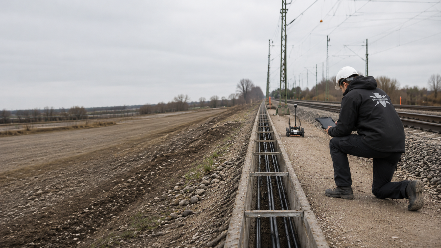
When railway bridges or culverts are replaced, removed or refurbished, structural designers and site management need investigations covering different areas and depths. FONTANA-EOD checks the UXO records against the abutments, piers, foundations, excavation support and construction phases. Send us the structural, foundation and demolition drawings so that we can define the investigation scope for each working area.
Distinguish abutments, piers and the culvert.
Identify piles, excavation support and excavations.
Keep records for each structural element.
For railway bridges and culverts, the available UXO information and investigation results are checked against the planned demolition, foundation and excavation works. Abutments, piers, piles, excavation support and culvert areas are assessed separately by position, depth and access. This establishes the investigations required before each construction section and the limitations that must be documented.
A total of 149 borehole surveys were documented during replacement of the grade-separated structure over railway line 2534 and the Xantener Straße railway bridge in Neuss. View project details.
Service areas:Downhole magnetometry / deep-ground survey
A railway bridge or culvert is not treated as one uniform construction site. Abutments, piers, slopes, piles, excavation support, the culvert invert and temporary working areas have different depths and access conditions.
Dividing the work by structural element supports design, tendering, construction and subsequent updates.
When existing structures are altered, some areas may only become accessible after removal of tracks, the bridge superstructure or foundations. The tender already defines when additional investigations will take place and what records must be available before the next specialist foundation or excavation stage. Investigations and protective measures for ground disturbance during demolition are also defined in advance.
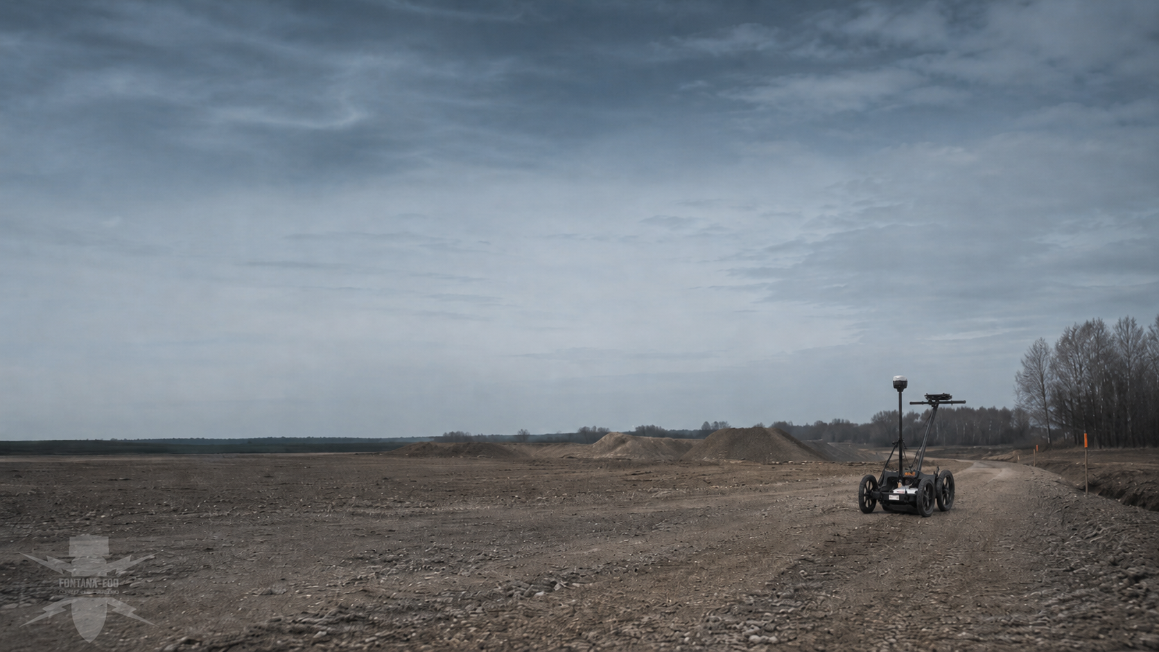
Removal of the existing structure, new abutments, piers, superstructure and changes to track alignment create several successive investigation areas. Early planning must account for temporary construction stages and inaccessible parts of the existing structure.
Investigations are updated by construction phase so that newly accessible areas can be used and earlier findings are not automatically carried over to changed geometries.
Plan the investigation stages for the replacement structure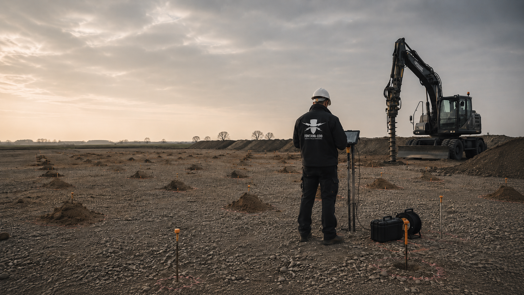
Abutment excavations, wing walls, approach slabs, slope cuts and utility connections combine area excavation with deep foundation or excavation-support locations.
Unobstructed areas, interference from existing structures and deep alignments are investigated separately, then brought together in records for the relevant structural element.
Assess abutments and deeper groundPier foundations may involve bored piles, driven piles, micropiles or other deep installation work. The relevant working volume regularly extends beyond a near-surface survey zone.
Coordinates, diameters, design depths, inclination and installation method determine the point-specific deep survey and subsequent documentation.
Prepare pile and pier locationsConstructing, extending or refurbishing a culvert affects its alignment, inlet and outlet, invert, slopes, chambers and utility connections. Access and water flow may change between construction phases.
Excavation, excavation support, dewatering and deep foundation locations are coordinated against the same drawings and level reference.
Assess the culvert and working areasTemporary bridges, temporary piers, crane positions, assembly areas, construction roads and track diversions require additional areas outside the permanent structure.
These temporary ground disturbances are not dismissed as logistics areas. They are assessed separately according to load transfer, excavation and foundation requirements.
Assess the interfaces with the railway route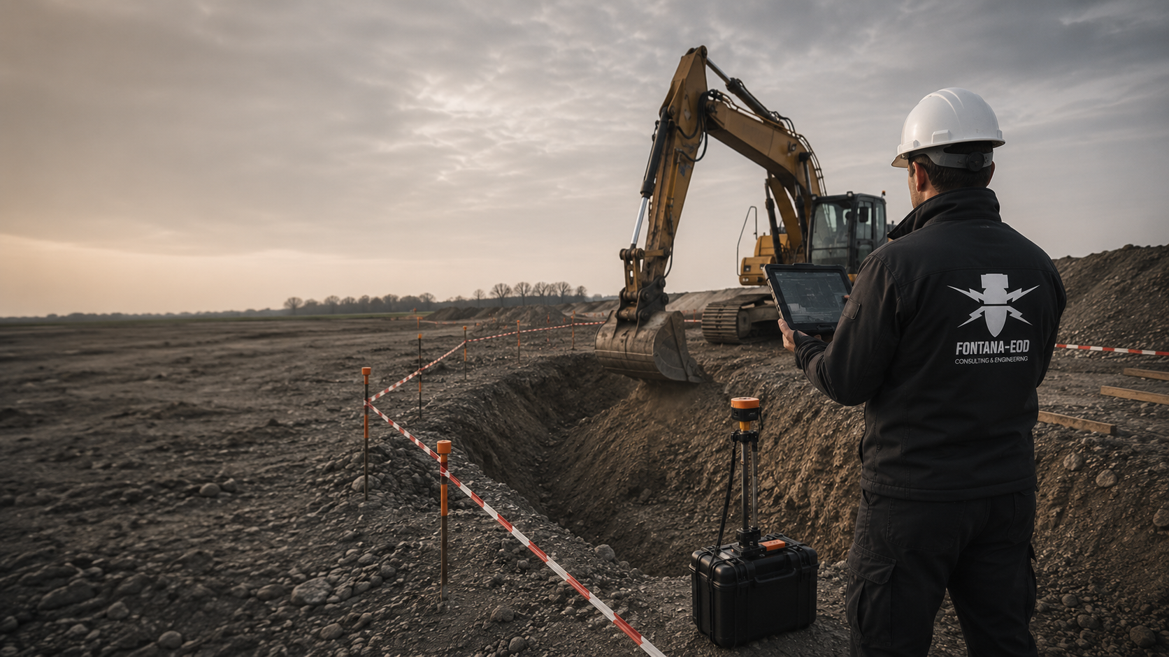
Existing foundations, reinforcement, utilities and previously built-over areas may limit preliminary investigation. Partial removal of the structure makes new working areas accessible.
The construction sequence is coordinated with additional detection work, deep investigation or investigation during construction, without treating outstanding areas as complete.
Coordinate demolition and excavation requirementsStructural design, demolition, foundations and access develop through several stages. Each significant change may alter the scope covered by existing evidence.
The bridge position, span, pier locations, culvert alignment and temporary diversion have not yet been finalised. A preliminary historical and spatial assessment can identify different suspected areas and investigation requirements.
Options are assessed not only in terms of the structure but also against additional investigation and access requirements.
Assess the suspected risk for each optionOnly limited preliminary surveying may have been possible beneath existing abutments, foundations or platform and track-superstructure connections. The appropriate method may change after removal.
The new construction stage is assessed by a specialist before the next excavation or foundation operation.
Plan the demolition sequence and follow-up investigationPiles, sheet piles, boreholes and anchors pass through defined point-specific or linear volumes down to considerable depth. A general area survey does not automatically address that geometry.
The point list, alignment, design depth and installation method are matched to the deep-ground survey.
Define the depth investigation for foundationsReinforcement, foundations, rails, cables, sheet piles and technical installations can obscure survey signals or prevent access along survey lines. These limitations are recorded for each part of the structure.
Suitable methods and investigation stages are specified for open areas and for areas that become accessible only after demolition.
Check interference and survey feasibilityChannel beds, banks and slopes may require different equipment, working platforms or access windows from the excavation on land. Water level and construction stage affect access.
The work is divided according to actual access and the geometry of the planned ground disturbance.
Assess channel beds and slopesFor an abutment, pier or culvert section, the records must show the area and depth investigated and any outstanding issues. A general site update is insufficient.
Point, area and section records are brought together for each structural component.
Define component status and handover requirementsExplosive ordnance investigation extends beyond the outline of the bridge. It must cover every volume of ground affected by demolition, excavation, foundations, excavation support, temporary works, utilities or access routes.
The conclusions are documented separately for each part of the structure and each depth range.
Starting point: Historical evidence concerns the railway or watercourse corridor, but the detailed geometry of the structure is still being designed.
Next step: Areas with suspected ordnance are compared with the design options, abutments, piers and temporary construction areas.
Required outcome: The design identifies which areas need further historical research, technical investigation or work during a later construction stage.
Assess the historical evidence for the structure corridorStarting point: An accessible abutment or slope area needs investigation before excavation and ground reduction.
Next step: An area survey method is selected to suit the target objects, surface and ground conditions.
Required outcome: The surveyed area, achievable investigation depth, interference zones and possible target locations are recorded with geographic coordinates.
Select a suitable area survey methodStarting point: The planned installation extends well below the near-surface investigation zone.
Next step: The borehole or depth investigation is designed around the alignment, point spacing, design depth and geometry of the future component.
Required outcome: Every point or section of alignment has a clearly defined depth status and a decision on the next step.
Investigate pile and excavation-support alignmentsStarting point: Foundations, reinforcement or a lack of access obstruct the future working volume.
Next step: The suitability of investigation after partial demolition, controlled exposure or explosive ordnance surveying during construction is assessed. The chosen approach is included in the construction programme.
Required outcome: The report distinguishes areas investigated in advance, areas that will become accessible later and areas where questions remain unresolved.
Prepare for investigation during a later construction stageStarting point: Excavation, dewatering, excavation support and utility connections affect different working areas.
Next step: Areas on land, the channel bed, slopes and deep investigation points are assessed separately to select suitable methods.
Required outcome: For every zone, the records show when and how it was investigated and to what depth.
Divide the culvert into investigation zonesStarting point: An anomaly or a find affects the excavation, a pile position or a temporary working area.
Next step: A survey anomaly is assessed by a specialist. If an unexpected suspicious object is encountered, work stops immediately. Leave it untouched and do not expose it further. Leave the immediate area and, in Germany, contact the police; outside Germany, follow the local emergency reporting procedure.
Required outcome: The find location, action taken, unresolved adjoining areas and decision on resuming work remain traceable.
Clarify reporting and recovery arrangementsBridge and culvert projects need records that bring together the structural geometry, survey data, investigated depth volumes and construction stages.
This allows a later design change, additional foundation or revised excavation to be checked against the scope of the existing records.
The structure number, railway line, track, chainage, alignments, abutments, piers, culvert and construction stages establish the spatial reference. Each report refers to the applicable drawing revision.
Temporary areas such as diversions, crane positions and assembly areas are included where relevant excavation or foundation work is planned.
Aerial photograph assessments, archive and authority information, known finds and previous reports are documented with the areas to which they apply.
Contradictions or missing appendices remain identified as outstanding design issues rather than being replaced with general statements.
Survey areas, borehole and pile positions, sheet-pile and anchor alignments, excavations and culvert areas are given unique identifiers.
Drawings, field records and processed data use the same identifiers so that no point is assigned to the wrong component or drawing revision.
The records describe the equipment, survey grid, borehole geometry, investigation depth, surface, ground conditions, access, water and slope conditions, and sources of technical interference.
If site conditions change during construction, the records clearly identify the conditions that applied to each investigation.
Anomalies, unusual signals, areas where data cannot be interpreted, exposure work and actual finds are distinguished and recorded by location.
Each unresolved area is assigned a specific additional investigation or follow-up measure.
Each abutment, pier, pile group, culvert, slope and temporary construction area has its own investigation status.
The completion record describes the area and depth investigated, outstanding work and the conditions for the next construction or foundation stage. Where exposure or clearance work has actually been carried out, the findings and clearance records use the same component and depth references.
The project file contains the historical evidence, survey areas and points, the demolition stage at the time of investigation, the results and outstanding work.
Even on projects lasting several years, earlier records must be checked to establish whether they cover new components or revised depths.
Site, as-built, demolition, foundation, excavation-support and construction-stage drawings are registered with their revision and scope.
The dossier identifies which documents supported the historical assessment, area survey or depth investigation.
Abutments, piers, wingwalls, piles, excavation supports, anchors, the culvert alignment and temporary areas use consistent identifiers.
Changes to quantities, positions, depths or component dimensions are recorded so that the revisions can be traced.
Survey lines, grids, borehole logs, investigation depths, positioning data and technical limitations remain linked.
Raw and processed data are filed so that each technical conclusion can be traced to its spatial basis.
Unusual signals, target locations, exposure work, objects causing technical interference and confirmed finds are labelled separately.
The status records show which points are complete, outstanding or require reassessment following a design change.
Areas investigated in advance, areas investigated after demolition and areas that will become accessible later are identified for each construction stage.
This keeps handovers between demolition, specialist foundation works, civil engineering and track construction clear.
The report, drawings, point lists, limitations and further measures are brought together for the client, designers and site management. Findings and clearance records are added where the corresponding exposure or clearance work has actually been carried out.
The conclusions apply to the documented design revision and construction stage. Relevant sections are updated when conditions change.
The work follows the structural design, access arrangements and construction stages. Each step resolves a specific investigation task within a defined area, point or depth volume.
Thorough preparation is particularly important when railway possessions, watercourse conditions and specialist foundation works have to be closely coordinated.
The existing structure, planned replacement or new construction, structural alignments, construction stages and required assessment are established from the current documents.
Abutments, piers, culverts, temporary areas and deep foundations are defined as separate working areas.
Historical assessments, official information, earlier surveys, ground investigation data and known finds are related to the structure corridor.
Data gaps are identified early so that they can be considered when comparing design options and preparing tender documents.
The location and depth of demolition, excavations, piles, excavation support, dewatering, utility diversions and temporary structures are described.
The sequence shows when each area becomes accessible and when a technical decision is needed.
Open areas, areas affected by technical interference, deep investigation points and areas accessible only after demolition are each assigned a suitable investigation or construction-monitoring service.
The investigation objective and the limits of the conclusions are clearly defined before the contract is awarded.
Areas, points, alignments, chainage, coordinate system, access routes, working platforms and operational time windows are coordinated.
Uncertainties about existing structures or utilities are resolved before site work begins.
Surveys, borehole investigations, controlled exposure or monitored excavation are carried out in accordance with the construction-stage and action plan.
Deviations in position, depth or construction conditions are recorded immediately.
Survey data, anomalies, findings and limitations are assigned to the relevant abutment, pier, pile, culvert or temporary structure.
Outstanding issues are assigned a technically justified follow-up measure.
The report, drawings, point status and outstanding work are prepared for the next construction section.
Design changes and additional ground disturbance are checked against the documented scope of investigation.
Explosive ordnance investigation must use the same geometry as the structural design and construction drawings. General area figures are insufficient for piles, excavation supports and working volumes close to the structure.
Each component area is assigned a spatially defined investigation task with clear depth limits.
The future outline of the structure is only the starting point. Demolition, excavations, working areas, slopes, pile and sheet-pile alignments, anchors, utilities, dewatering, crane positions, assembly areas and temporary diversions are also considered. Each ground disturbance is described by location, width, depth and construction stage.
Open approach areas can be investigated using a suitable surface survey method. Existing foundations, reinforcement, rails and technical installations can restrict the survey. The interference zone is mapped and is not treated as an area without anomalies.
If investigation from the surface does not cover the required depth volume, suitable additional investigation is planned. A depth investigation is designed around the future installation volume of piles, boreholes, sheet piles or anchors. Point spacing, survey geometry, design depth, diameter, inclination and casing must suit both the planned component and the installation method.
For culverts, the alignment, inlet, outlet, slopes, invert, chambers and utility connections are assessed separately. Water level, access and working platforms can affect when an investigation is possible and which zones become accessible only after site setup.
The overall conclusion is based on these individual records. An investigated abutment area does not justify a blanket conclusion about pile toes, pier positions or temporary ancillary areas.
The excavation, wingwalls, approach slab, backfill, slope and utility connections are recorded as a connected working area divided into clearly defined parts.
Deep foundations and excavation-support alignments have their own point or linear investigation records.
Each pier location is linked to the pile layout, alignments, design depths, diameters and construction stage.
Relocated or additional piles are assessed against the existing investigation volume before installation.
Excavation-support alignments and anchor fans affect linear or inclined volumes at depth. Their status cannot be inferred from a general area survey.
Survey geometry and any alternative investigation geometry are agreed with the specialist foundation contractor and surveyors.
The inlet, outlet, invert, slopes, chambers and connecting utilities are divided according to access and construction stage.
Working areas on land and those affected by water may require different methods and investigation times.
Built-over or reinforced areas are initially recorded as having methodological limitations. Access is reassessed after partial demolition.
The subsequent records identify which investigation was carried out at each construction stage.
Crane positions, temporary bridges, assembly areas, access routes and diversions are included where excavation, foundations or relevant load transfer are planned.
Temporary use does not remove the need for explosive ordnance assessment.

The available evidence of ordnance and previous investigations is first reviewed for demolition, excavations, abutments, piers, pile foundations, sheet piles, anchors, culverts and temporary diversions. This establishes whether further investigation is needed and its scope. The historical evidence is related to the specific geometry of the structure and its construction stages.
Assess the basis for suspicion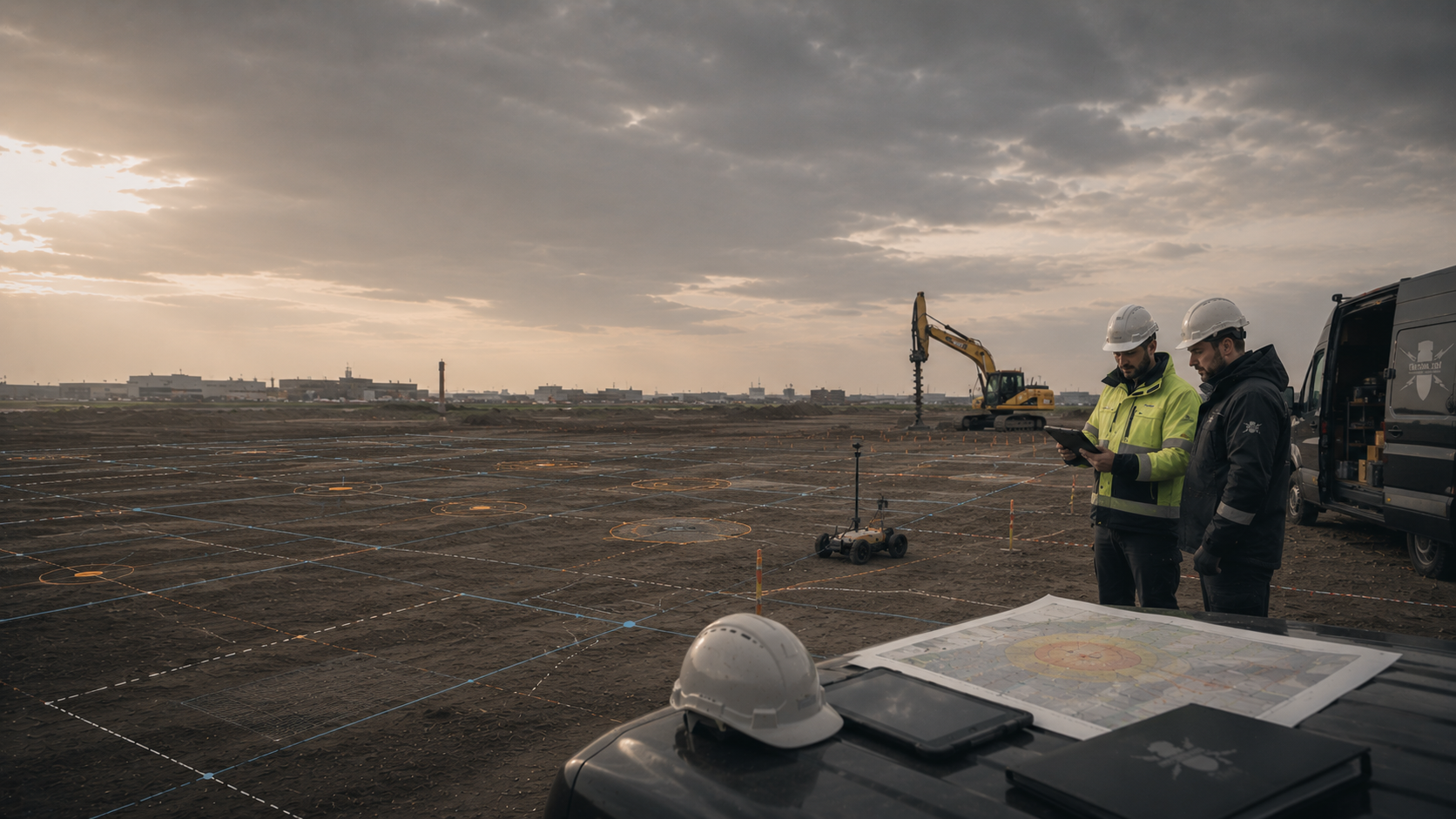
Bridges and culverts do not have a uniform investigation area. Open approaches, built-over areas, reinforced foundations, slopes, watercourse edges and deep localised ground disturbance must be assessed separately. The appropriate method depends on the component, depth, ground conditions, technical interference and construction stage.
Choose methods for open and built-over areasThe investigation strategy combines historical research, area surveys, depth investigations and work during construction. The deciding factor is the assessment required for each part of the structure at the relevant construction stage.
An abutment, a deep pile and a demolition area that becomes accessible later may therefore require different investigations.
Assesses the evidence of ordnance, previous land use and areas potentially affected by ordnance within the structure and railway corridor.
It establishes the spatial basis but does not detect objects present today or replace technical investigation.
Investigates suitable accessible approaches, excavation areas or slopes before ground disturbance.
Existing structures, reinforcement, rails and utilities can limit interpretation and, where they do, require additional methods.
Investigates defined points, alignments and depth volumes for piles, sheet piles, anchors, boreholes and deep foundations.
The survey geometry is directly related to the future component and its installation method.
In suitable excavation areas, each working layer is surveyed and assessed by a specialist. This is followed by controlled excavation in layers and an additional visual inspection. These steps are repeated to the agreed base of excavation; simply watching the excavator is insufficient.
It does not cover deeper components or components outside that area without separate supporting investigation.
Area clearance addresses a defined volume of ground in accordance with the agreed clearance objective. Ordnance recovery concerns finds confirmed by specialists within the permitted scope of work and the responsibilities of those involved.
Findings, handover and outstanding areas are documented by component and location.
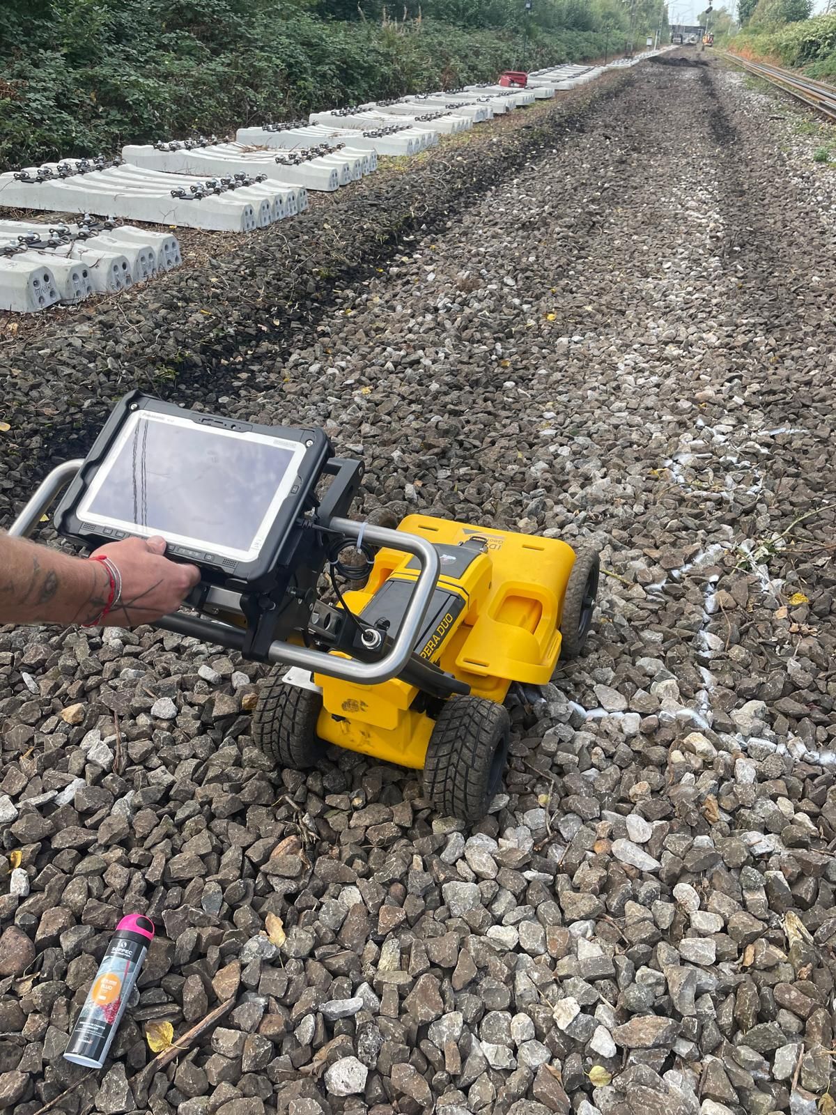
Magnetometry detects magnetic anomalies, particularly those caused by ferromagnetic objects. In suitable unobstructed areas, the results can be used to produce a georeferenced anomaly map.
Rails, reinforcement, foundations, vehicles and other masses of iron can mask the signals. The survey area, interference zones and limitations are documented in relation to the planned ground disturbance.
TDEM measures time-dependent electromagnetic responses from conductive objects and can provide additional investigation of selected areas or anomalies.
Existing installations, utilities, reinforcement, target size, depth and survey geometry limit interpretation. The results identify assessed anomalies; they do not establish the identity of an object.
Ground-penetrating radar records contrasts in subsurface reflections. Layers, buried installations and structural changes can provide additional information for excavations and demolition areas.
Moisture, soil conductivity and heterogeneous fill limit penetration and interpretation. Radargrams and location plans show structures and outstanding areas. A reflection does not identify unexploded ordnance.
Railway bridges and culverts require close coordination between structural design, surveying, specialist foundation works, construction stages and technical documentation.
Everyone involved must use the same drawing revision. The reports show which areas and depths were investigated and where the method reaches its limits.
FONTANA-EOD divides the project into the volumes of ground actually affected: approaches, excavations, abutments, piers, piles, excavation supports, culvert zones and temporary working areas. This allows a suitable scope of services to be defined for each area.
Before fieldwork, the drawing revision, alignments, coordinates, design depths, access, interference sources and construction stages are checked together. Missing information is clarified before specialist foundation work begins.
During the work, survey data, borehole positions and findings are linked directly to the component and drawing revision. Changes in location, depth or construction method lead to a documented reassessment.
Methodological limitations remain explicit. Existing foundations, reinforcement, water, slopes or lack of access are not obscured by general statements; they are addressed through a suitable follow-up measure.
The final documents describe the area and depth volume actually investigated, together with remaining limitations and outstanding follow-up work.
Abutments, piers, piles, excavation supports and culvert areas have their own identifiers.
The structural design, survey records, borehole point list and UXO investigation records refer to the same construction design revision.
Methods are selected according to the target object, depth, ground conditions, existing structures and access.
New access after demolition and additional ground disturbance are incorporated into the investigation.
Findings are handed over with precise locations and dealt with through the agreed reporting procedure.
Reports identify the areas covered, limitations and any measures still required.
Surface methods can investigate suitable open areas. Whether piles, boreholes, sheet piles or anchors require a depth or borehole investigation depends on factors including the grounds for suspicion, the depth of disturbance and the effective investigation depth of the surface survey. For areas accessible only after partial demolition, the timing and method of investigation are assessed. Explosive ordnance surveying during construction is considered only if it is technically suitable for the planned work.
For each part of the structure, the completion records describe the area and depth volume actually investigated, the method used, interference and access limitations, and the follow-up decision still required.
Bridge projects bring together several design disciplines, contractors and public authorities. Before work begins, responsibilities are agreed for updating point lists, coordinating construction stages and passing on the associated records.
The technical investigation, authorisation for the next construction step and official decisions about finds remain distinct.
Define the objectives for the structure, construction stages, decisions required and priorities. They provide historical, structural and operational information and commission the necessary specialist services.
Where there are several work packages or construction stages, they establish consistent rules for data and handover.
Translates the project into excavations, components, piles, excavation supports, anchors, culvert alignments and temporary working areas. It incorporates explosive ordnance investigation into the comparison of options, tender documents and programme.
Design changes are communicated with clearly defined geometry and revision references.
Provides borehole positions, ground data, levels and positional references, and helps define the relationship between investigation volumes and foundation volumes.
Borehole and survey data are coordinated with the explosive ordnance investigation point register.
Carries out excavations, demolition, piling, excavation support, dewatering and temporary works in accordance with the approved drawing revision.
Deviations in location, depth or construction method are reported before the next ground disturbance.
Assesses the evidence of ordnance and project data, develops the agreed approach, carries out specialist services within the commissioned scope, and documents results and limitations.
The investigation is coordinated with the construction sequence, operator and local contacts responsible for dealing with finds.
In Germany, the ordnance disposal services of the federal states and the locally competent authorities carry out hazard-response and find-management duties. Their involvement is established for the project location; outside Germany, local responsibilities apply.
Contacts and reporting procedures for the specific project location are documented before work begins.
Depending on local procedures and the construction task, the public order authority and building control authority may be involved. Their requirements are assigned to the specific site, section and drawing revision. The specialist investigation, railway operating permission to work and official decisions on finds are documented separately with their respective contacts.
Qualifications, risk assessment, work organisation and documentation depend on the task, the evidence of ordnance and actual finds, the project location, and the specific construction and access conditions.
Structural design and explosive ordnance services must describe the same working volume, while fulfilling different technical and legal tasks.
In Germany, § 7 SprengG concerns the commercial authorisation for activities requiring authorisation; § 20 SprengG concerns the certificate of competence of responsible persons. Under § 1b SprengG, searching for found munitions also counts as handling them. The requirements applicable to the project depend on the activity actually commissioned.
The risk assessment considers excavations, piling and excavation-support works, demolition, watercourses and slopes, equipment, personnel, shelters, escape routes and communication. It is aligned with actual construction and operating conditions.
DGUV Information 201-027 supports risk assessment for ordnance clearance work. The Baufachliche Richtlinien Kampfmittelräumung set requirements for investigation, clearance concepts, quality and documentation within their defined scope of federal responsibilities. Their application to the specific bridge or culvert project is clarified separately.
If a suspicious object is found, stop work in the affected area immediately. Do not touch or move the object, leave the danger area and keep others away without putting yourself at risk. In Germany, notify the police immediately on 110; outside Germany, use the local emergency reporting procedure. Then inform site management.
Contractual acceptance, authorisation for the next construction section and official decisions about finds are separate processes. The documents and responsibilities required for each are agreed before work begins.
The First Ordinance to the German Explosives Act (1. SprengV) includes requirements for specialist competence and state-recognised training courses. For investigations at bridges, culverts and their foundations, qualifications are matched to the commissioned scope of work.
DGUV Rule 113-003 concerns the dismantling or destruction of explosives or corresponding objects and also includes the disposal of found munitions. It applies according to this field of activity; it does not replace a risk assessment specific to the planned ground intervention.
Structure areas, survey areas, points, depths, methods, quality requirements and the records to be delivered are clearly specified.
Construction equipment, specialist foundation works, demolition, slopes, proximity to water, protection zones and reporting procedures are assessed for the specific project.
Companies, responsible persons, appointments and specific tasks must match the scope of services.
Procedures cover unusual findings, finds, securing the area, the chain of responsibility and resumption of work.
Structural and point geometry, construction stages, access, qualifications, data formats and acceptance criteria are described on a comparable basis.
Provisional items have a clear technical trigger.
The drawing revision, surveying, access routes, exclusion and working areas, equipment, briefings and contacts are checked together.
Unresolved issues are decided before the first ground disturbance.
Work is suspended in the affected area.
If a suspicious object is encountered, immediate safety measures and prompt emergency reporting apply; further action follows the instructions of the competent authority.
The working documents provide technical and spatial traceability. They link parts of the structure, investigated depths and construction stages to the corresponding results and limitations.
All drawings and lists must use the same component and point identifiers.
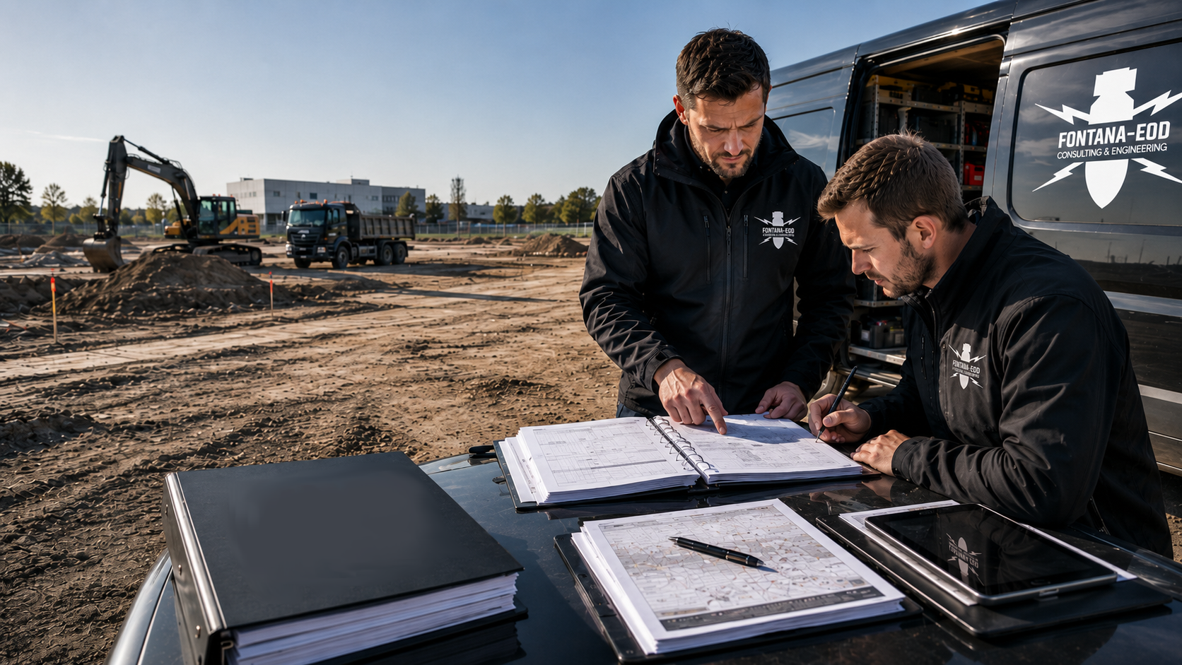
Abutments, piers, culverts, foundations, excavation supports, demolition zones and temporary areas are included in a common drawing structure.
Each investigation status remains linked to the applicable construction stage.
Define structure and construction-stage referencesThe evidence of ordnance, previous land use and gaps in spatial data are related to the structure corridor and design options.
This allows investigation areas to be prioritised before the final construction design is complete.
Clarify historical suspicion indicators
Open approaches, survey grids, interference zones and assessed anomalies are shown with geographic coordinates.
The map also identifies areas where existing structures or lack of access prevented a reliable investigation.
Prepare the technical scope of the area investigationCoordinates, design depths, borehole or survey geometry, results and outstanding issues are documented for each component.
This allows design changes to be checked specifically against the existing investigation volume.
Coordinate records for deep investigation pointsNewly accessible areas, excavation layers, stop points, findings and handovers are linked to the structure and construction-stage drawing.
Areas not investigated remain identified in the project file.
Monitor demolition and excavationThe final documents bring together the area, depth, method, findings, limitations and follow-up measures for each part of the structure.
The conclusion remains limited to the documented design revision and construction stage.
Have the project file reviewed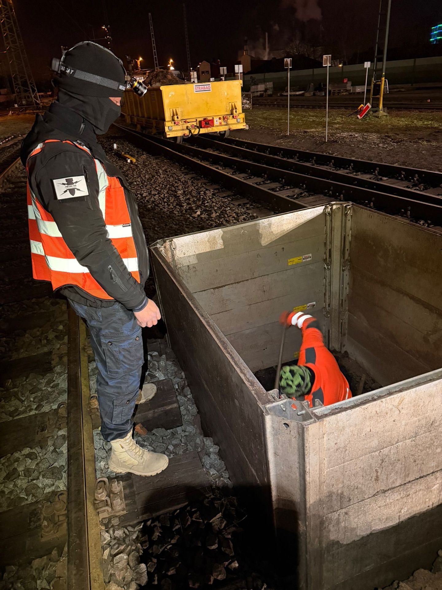
Coordinate track construction, crossings, railway power and excavation stages within the railway project.
Other railway and route projectsClarify the evidence of ordnance, previous land use and spatial priorities within the structure corridor.
Assess historical evidence of suspected ordnanceInvestigate open approaches and excavation areas using methods suited to the target object, surface, ground conditions and interference.
Select a suitable area survey methodPrepare piles, sheet piles, anchors and borehole positions with their own investigation geometry and design depths.
Investigate deep foundation volumesAssess whether explosive ordnance surveying during construction is suitable for excavation areas that become accessible later or cannot be adequately investigated beforehand.
Identify the role of construction-stage measures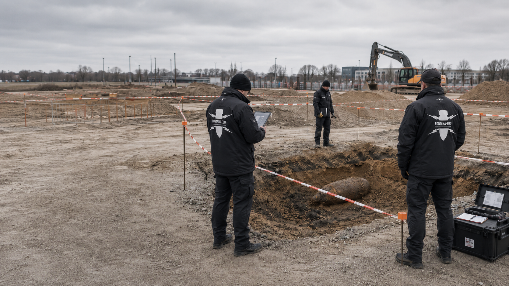
Clarify confirmed finds, specialist work and regional handover responsibilities.
Clarify reporting and recovery arrangementsExplore procurement, quality control, point status, construction-stage handover and final documentation.
Prepare procurement and component recordsHave structural, foundation and construction-stage documents reviewed to determine the appropriate scope of services.
Enquire about a structure and submit the relevant documents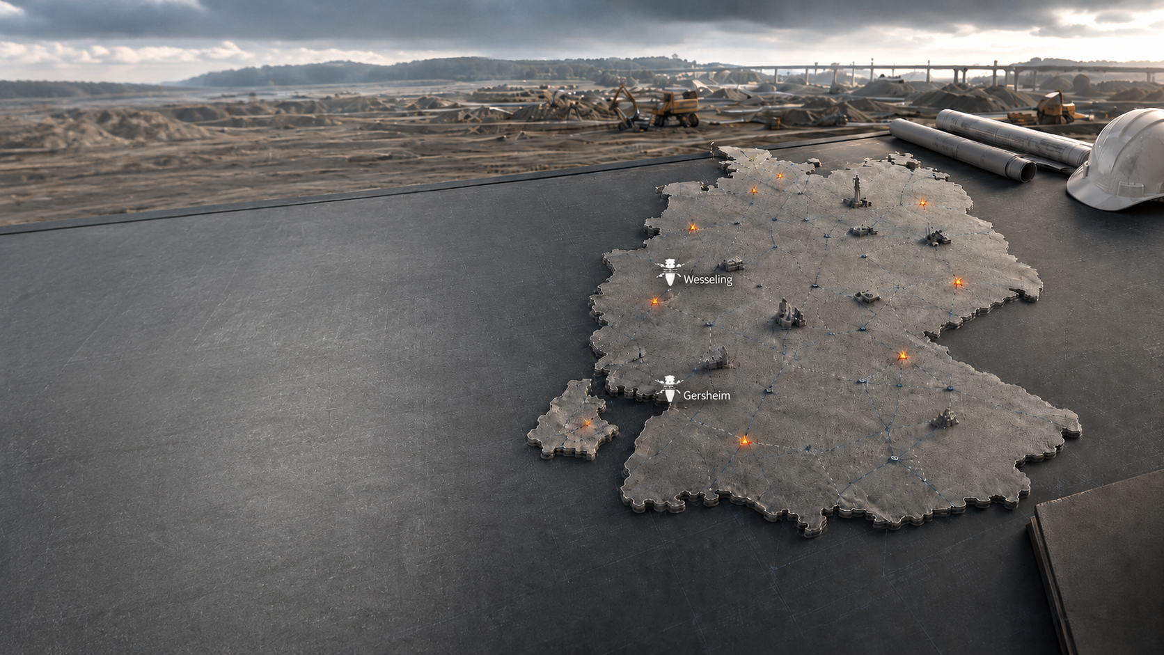
Alongside the project location, provide the structure number, railway line, track and chainage. Mark abutments, piers, culverts and temporary construction areas on the drawing. Include existing official correspondence with its date and spatial reference; it must not be applied to neighbouring structures without checking.
Compare the documented investigation depth with the planned piles, anchors and excavation bases. The records must show the ground or structural surface from which depths are measured. A revised foundation requires a fresh comparison with the investigated volume.
Check evidence against the interventionStructural design, demolition design and explosive ordnance investigation address different tasks. Those involved must agree when an area is accessible and which investigation is required before the next ground disturbance. An investigation does not replace a structural or construction-operational decision.
Explore the technical principlesTechnical information
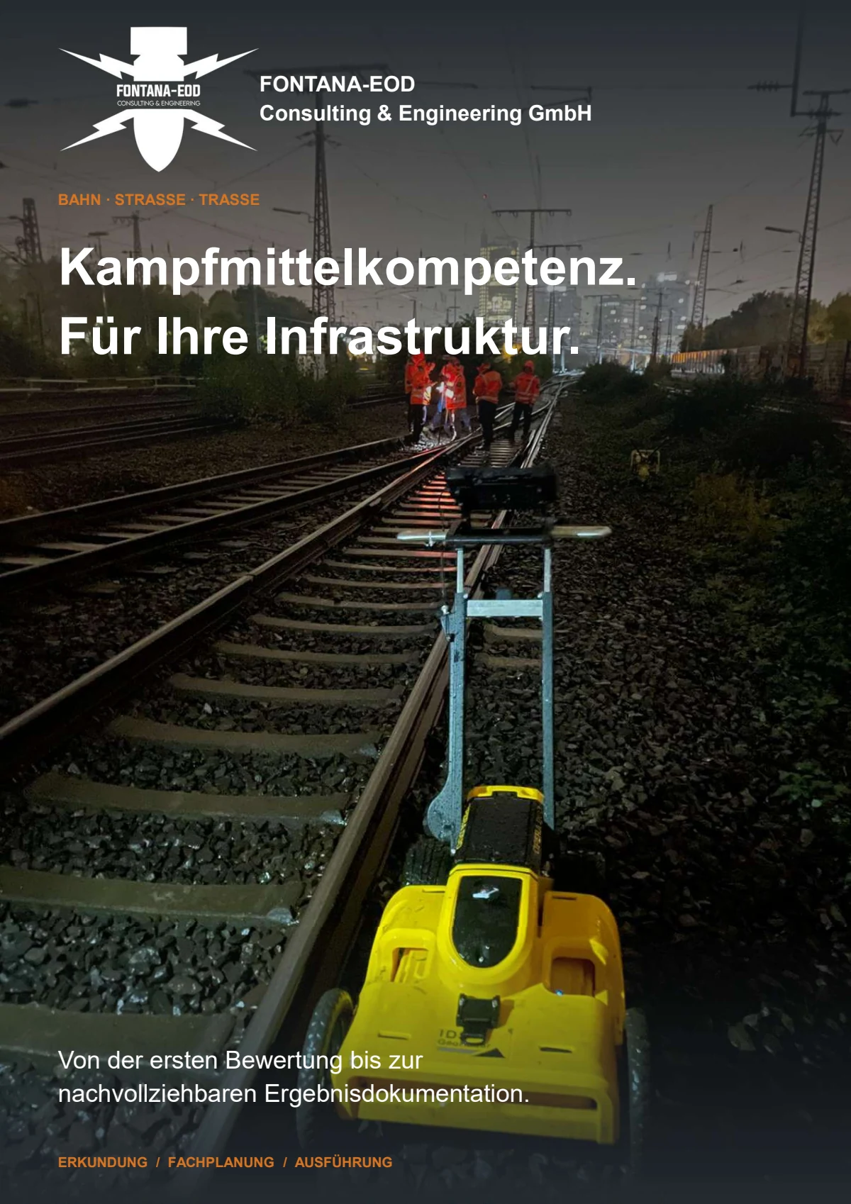
The brochure shows how FONTANA-EOD combines historical investigation, specialist planning, surveying and construction supervision in infrastructure projects. It explains trackside constraints, method selection and limitations, and result documentation.
Assessment should begin as soon as design options, the structure location, the extent of demolition and likely ground disturbance can be identified. Early design stages allow review of the historical evidence of ordnance, existing reports and gaps in spatial data. Before tendering, abutments, piers, piles, excavation supports, excavations, slopes, culvert alignments, temporary diversions and utility diversions must be defined, including depths and construction methods.
Abutments, piers, wingwalls, approach slabs, foundation points, sheet-pile and anchor alignments, slopes, working areas, culvert inlets and outlets, and temporary access routes have different area and depth geometries. Records for an accessible surface therefore do not automatically apply to deep piles, built-over zones or temporary working areas outside that footprint.
Key documents include the current site and structural drawings, alignments and chainage, as-built and demolition drawings, the foundation and excavation-support concept, borehole and pile lists, utility and drainage drawings, ground investigation data, construction stages, possession windows, and existing aerial photograph assessments, official documents and previous survey or clearance reports. Temporary diversions, crane positions and assembly areas should also be included.
Official information and requirements are submitted with their dates, complete appendices and spatial references. In Germany, the involvement of the relevant KBD, KMBD or KRD and the local public order authority is clarified for the project location; outside Germany, the local allocation of responsibilities applies. Building control and the operator may have additional requirements of their own for the construction sequence and access.
This depends on the required investigation depth and survey conditions. A surface survey covers only the volume of ground that can be reliably assessed under those conditions. If this is insufficient for piles, boreholes, sheet piles, anchors or deep foundations, additional depth investigation is planned. It is matched to the coordinates, design depth, component geometry and installation method.
Existing foundations, reinforcement, sheet piles, utilities and rails can obscure geophysical data and restrict access. These areas are not automatically classified as being without anomalies. Depending on the construction stage, options include investigation after partial demolition, alternative survey methods, borehole or depth investigation, controlled exposure or a measure carried out during construction.
If an unexpected suspicious object is found, stop work. Do not touch, move or uncover it further. Leave the immediate area and warn others without putting yourself at risk. In Germany, notify the police on 110; outside Germany, use the local emergency reporting procedure. The competent authorities determine what happens next; a project enquiry does not replace reporting the find.
Inlet and outlet areas, slopes, channel beds and banks, working platforms, dewatering, excavation support and utility connections are planned separately. The key questions are which areas are actually accessible and which volumes of ground are affected by piles, sheet piles, excavation or demolition. Working areas on land and in the water may require different methods and involve different responsibilities.
The records link the structure and drawing revision, investigated subareas, borehole and pile positions, investigation depths, survey conditions, interference zones, results and follow-up measures. For each component area, they must show the working volume covered and which areas can only be investigated after demolition, at a later construction stage or using another method.
Key factors are the number and depth of foundation and excavation-support points, the size and accessibility of excavations, the existing structure and reinforcement, watercourse and slope conditions, possessions and construction stages, existing utilities, required methods, surveying, data and documentation requirements, and possible repeat mobilisations after partial demolition. A reliable estimate therefore requires the current structural and construction design.
An initial enquiry should show which components will be replaced, given new foundations or demolished, and which volumes of ground will be affected.
Early design revisions can also be reviewed if the options, alignments and likely depths of ground disturbance are sufficiently clear.
Provide the structure number, railway line, track, chainage, site and as-built drawings, planned options, demolition and construction stages, and the affected abutment, pier and culvert areas.
Temporary diversions, crane positions and working platforms should also be shown.
Include pile, borehole, anchor and sheet-pile lists, design depths, diameters, excavations, slopes, dewatering and excavation geometry.
If changes have been made, clearly identify the current approval or revision status.
Relevant documents include aerial photograph assessments, official correspondence, previous survey or clearance reports, ground investigation data, utility drawings, reinforcement and as-built information, and existing reports of finds.
Also state when the results are needed and for what purpose: design, tendering, specialist foundation work, site management or project completion.
For an initial review, site and structural drawings, a description of demolition and new construction, planned foundation types, maximum depths, construction stages and existing ordnance evidence are often sufficient.
FONTANA-EOD then identifies the historical research, area surveys, depth investigations or services during construction required for each part of the structure.
Abutments, piers, culvert, slope, working area and temporary areas.
Piles, sheet piles, anchors, boreholes, excavations and maximum design depths.
Existing structures, demolition, watercourses and slopes, possession windows and construction stages.
Basis for design, procurement, specialist foundation work, site management or the project file.
Whether historical aerial photograph analysis, explosive ordnance surveying, surface surveying using GPR, magnetometry or TDEM, deep-ground surveys, downhole surveys, excavation supervision, area clearance or ordnance recovery is needed depends on the location, ground disturbance, depth, ground and existing documents. An early ordnance assessment provides clarity for tendering, programming, occupational safety and construction.
FONTANA-EOD combines its Section 7 SprengG licence, specialists holding Section 20 SprengG certificates of competence, suitable survey and clearance methods, and traceable documentation. Send the site plan, depth of ground disturbance, construction phase and existing documents for an initial technical assessment.


