Project pathway
The quickest route to the right decision.
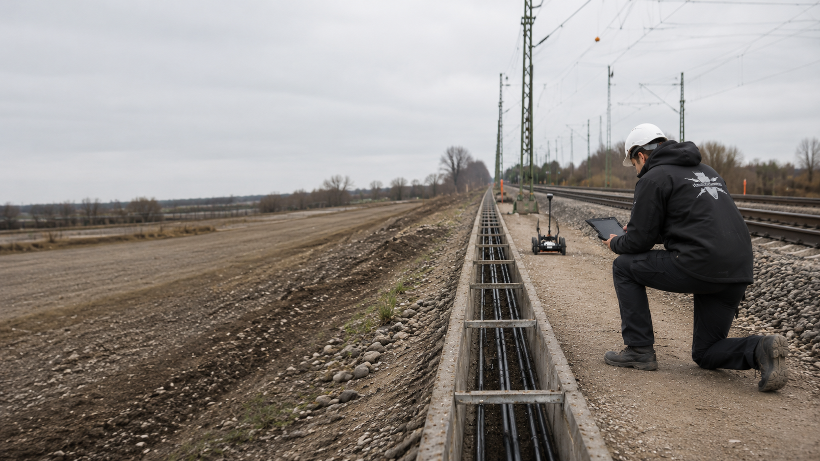
Overhead line designers, traction power project managers and contractors need to relate mast foundations, gantries and cable trenches to the available evidence of ordnance. FONTANA-EOD reviews the point list, foundation data, existing utilities and construction conditions. Submit these documents with the depths of ground disturbance and construction stages so that investigations and records can be specified for each location and cable section.
Identify masts, gantries and cable alignments.
Map foundations and working volumes.
Document the results for each location.
For railway power and overhead line works, investigation requirements are established for each mast, gantry or installation point and the associated cable corridor. Foundation size, depth and existing utilities guide the investigation design.
Metallic and electrical influences can limit survey methods. Revised locations or depths require a fresh comparison with the documented scope of investigation.
The records for Betriebshof Heerdt – Fahrleitungen in Düsseldorf list drilling for explosive ordnance investigation and documentation in August 2026. The project reference concerns investigation of the ground around the overhead line installations. View project details.
Service areas:Downhole magnetometry / deep-ground surveyDocumentation and interpretation of survey data
Railway power and overhead line projects involve many localised and linear ground disturbances. Mast locations, gantries, cable trenches, earthing and installation areas differ in depth, construction method, interference and operational access.
The technical work is therefore defined for specific components and working volumes. Only comparable points and route sections are combined within a common scope of services.
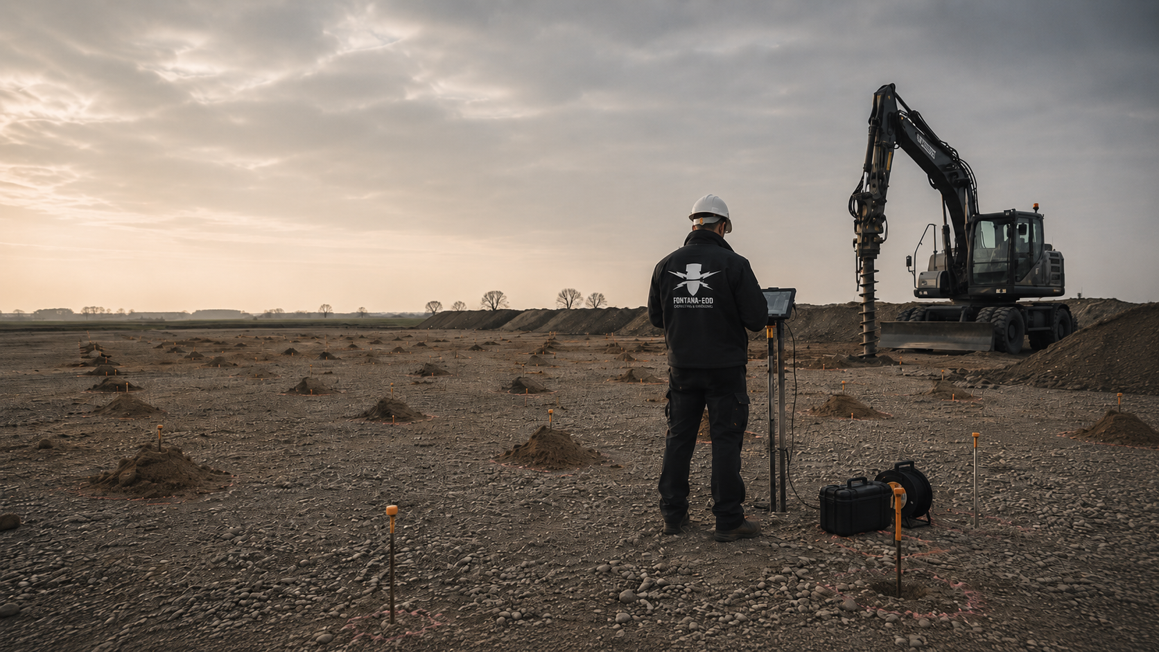
New, replacement and relocated masts cause localised ground disturbance. Foundation type, dimensions, installation depth and the working volume required vary with the design and construction method.
Explosive ordnance investigation is designed for each mast position. Surface surveys, borehole surveys and any necessary alternative investigation geometry are planned to cover the future foundation volume.
Define mast positions and investigation depths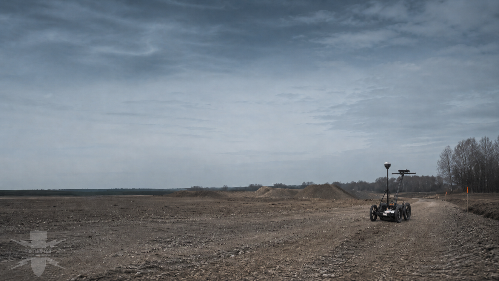
Gantries and anchorage structures connect several support points, tie anchors or foundations. Their geometry may extend beyond the visible mast location and require additional working volumes.
All points are recorded together with alignments, foundation dimensions, access and the assembly sequence. The investigation records nevertheless remain traceable for each individual geometry.
Investigate gantry and anchorage foundations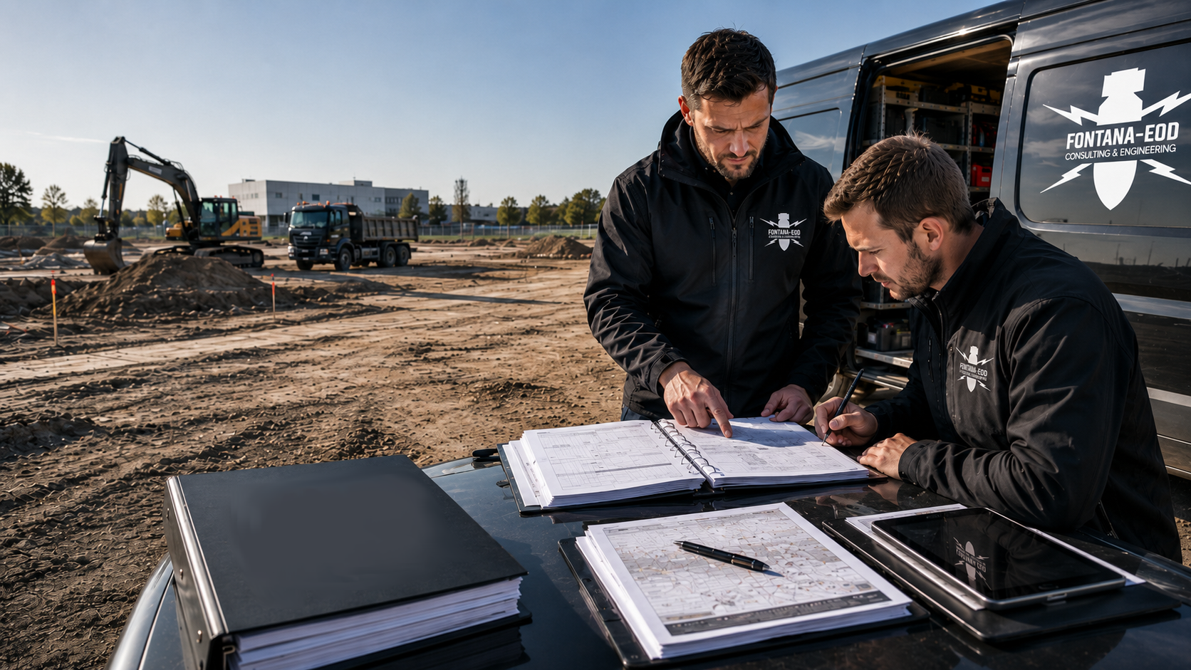
Power and feeder cables often run alongside the track, cross structures or connect to switching and supply installations. Existing cables, earthing systems and technical installations affect both the construction sequence and survey conditions.
The alignment, trench depth, working width, chambers and crossings establish the spatial scope of investigation. Deep or inaccessible sections are assigned their own follow-up measure.
Structure the cable route and investigation recordsInstallation areas contain foundations, cable ducts, earthing grids, reinforcement and extensive technical equipment. New construction, extensions or demolition may affect several areas and depth volumes at once.
Open outdoor areas, areas close to structures, deep foundations and future excavation areas are assessed separately. The operating conditions form part of work preparation.
Assess the installation areaEarthing conductors, return-current connections and equipotential bonding are often located in narrow corridors close to the track and connected to existing cables and installations. New or revised systems may require additional trenches, connection points and depths.
Explosive ordnance investigation is coordinated with existing utilities and the construction geometry, without replacing electrical design.
Assess railway engineering interfaces
Removing existing masts, foundations, ducts or utilities exposes ground that was previously built over. Demolition may also require larger working volumes than the subsequent new construction.
The work is divided by demolition step, excavation layer and reuse of the location. For areas that cannot be surveyed beforehand, the suitability of a later survey or explosive ordnance surveying during construction is assessed.
Provide specialist support during demolition and excavationExplosive ordnance investigation is not determined by the number of masts alone. The drawing revision, foundation geometry, surrounding utilities, construction method and operating conditions determine the service needed at each location.
Before work on new mast foundations, gantries, switching installations, cable routes or demolition excavations, the available evidence of ordnance must be clarified. Investigation requirements are related to the planned locations, working areas and depths.
For new overhead line or railway power sections, mast positions, cable routes, switching points and construction stages must be compared with the historical evidence of ordnance at an early stage. Design options may involve different ground disturbances and therefore different investigation requirements.
Early assessment supports route selection, programming and tendering, without pre-empting the later investigation of individual points.
Clarify ordnance evidence for the upgrade sectionCoordinates, foundation type or installation method may change between design and construction. If the geometry changes later, the existing survey is checked to establish whether it still covers the working volume.
The applicable drawing revision is therefore agreed before fieldwork. At each revision, existing results are checked against position and depth.
Use a consistent drawing revision and point listFor large numbers of mast locations, the core scope, casing, design depth, survey length, alternative points, boreholes that cannot be formed and required documents must be clearly specified.
Overall quantities without point and depth references make comparison, measurement of completed work and acceptance difficult. Each status is linked to a unique identifier.
Prepare procurement and point recordsIncomplete or contradictory as-built documents affect borehole positioning, equipment setup and survey conditions. Before ground disturbance, utility and installation information must be checked against the actual site conditions.
If a location remains inaccessible, a technically sound alternative or follow-up solution is developed.
Check conflicts between existing installations and planned pointsPossessions, electrical switching states, access, safety arrangements and other trades working nearby determine when a point or route section can be investigated.
Explosive ordnance investigation is incorporated into these arrangements. Operational authorisation and the status of the specialist investigation remain documented separately.
Coordinate operational interfacesA survey anomaly within the working volume must be assessed in relation to its position and depth. Known technical causes, unclear signals and actual finds require different follow-up decisions.
The point remains open until the technical assessment is complete. A general statement about the surrounding area does not replace that assessment.
Clarify the findings and handover processMast lists, cable drawings and investigation reports must use the same identifiers and coordinates. Historical evidence is related to the specific foundation and cable-route geometry.
Each status remains linked to the point identifier, drawing revision, design depth and investigation volume actually covered. If these change, existing results are checked to establish whether they still cover the new position or depth.
Trigger: Historical evidence exists for the railway line or installation area but has not yet been related to mast positions, cable routes and switching locations.
Technical step: Areas with suspected ordnance and data gaps are compared with the current design and prioritised by type of ground disturbance.
Required outcome: A spatially justified basis for the technical design of individual points and routes.
Assess the corridor with suspected ordnanceTrigger: Coordinates, foundation dimensions, design depth and installation method have been agreed.
Technical step: The entire working volume is translated into point-specific investigation and survey geometry; casing, survey length and possible alternative points are planned.
Required outcome: A location-specific status stating the investigation depth reached and clear limits.
Investigate the depth volume of the mast foundationTrigger: New feeder, control or earthing cables run alongside existing utilities, tracks and structures.
Technical step: The trench alignment, width, depth, chambers and crossings are divided according to survey feasibility and subsequent excavation.
Required outcome: A section-specific assessment identifying areas investigated in advance, unresolved zones and areas requiring investigation during construction.
Plan the cable trench and excavation sectionsTrigger: A switching or feeder area contains foundations, reinforcement, cable ducts, an earthing grid and operating equipment.
Technical step: Open subareas, deep individual points and areas accessible only after demolition are assessed separately.
Required outcome: A clear distinction between areas where survey data can be interpreted and areas requiring alternative measures.
Investigate the installation area and interferenceTrigger: Utilities, existing structures, insufficient equipment space or drilling obstructions prevent the planned investigation geometry.
Technical step: An alternative point, additional borehole, revised geometry or alternative construction method is assessed against the original working volume that needs investigation.
Required outcome: A justified revision that avoids an uncontrolled shift in the investigated volume.
Document the technical basis for an alternative pointTrigger: A relevant point lies within a foundation, cable or installation volume and requires clarification before the next activity.
Technical step: The position, depth, working environment and responsibilities are assessed; communication within the project and on site follows the agreed procedure.
Required outcome: A documented point status and a clear follow-up decision for the affected working volume.
Clarify point status and follow-up measuresWhere there are many mast positions, each survey dataset must be traceable to the correct point. Mast lists, borehole logs, survey data, anomalies and further measures are therefore linked through the same point identifier. The applicable drawing revision remains clear.
The records are useful to site management and contractors only when the point status, depth reached and technical limitations are clearly identified.
For repeated foundation works, the records must also show the chronological sequence of points. This establishes whether a survey took place before or after utility diversions, demolition, setting out or construction of a haul road, and whether the technical surroundings changed before foundation work began.
Each location has a unique identifier with the railway line, track, kilometre reference or chainage, coordinates, component type, foundation type and drawing revision.
Cable sections, switching points and earthing connections use the same spatial referencing system.
Aerial photograph assessments, historical documents, official information, earlier finds and existing survey reports are documented with their scope of application.
This information shows why a point is being investigated and which data gaps remain before construction.
Starting coordinates, drilling method, casing, borehole depth, survey length, equipment configuration, obstructions and deviations are recorded for each location.
The dataset must show which part of the future foundation volume was actually investigated.
Rails, cables, earthing systems, existing masts, reinforcement, installations and the electrical operating state are documented where relevant to the suitability of the method.
This makes the survey conditions and possible limitations technically traceable.
Unusual signals, known technical causes, additional surveys, exposure work and outstanding measures use the same point identifier.
A point is complete only when the agreed scope of investigation or decision-making has demonstrably been fulfilled.
The point list, site drawing, investigation status, limitations and further measures are brought together for site management and contractors. Where exposure or clearance work has actually been carried out, the findings and clearance records are added to the documents for that location.
New or relocated positions are checked against the documented existing investigation before being included in the project's work authorisation.
Site management must be able to establish which location was investigated, how deep the investigation extends and which tasks remain outstanding.
The drawing revision, foundation data, survey logs, anomalies and handover documents are therefore kept together. Results apply only to the documented locations.
Links mast, gantry, switching and cable identifiers to coordinates, chainage, drawing revision and construction section.
Changes, deleted points and new locations remain traceable throughout the project.
Foundation type, diameter, length, design depth, drilling or installation method and the working volume required are documented for each point.
This allows the investigation geometry to be compared with the work actually carried out.
The borehole path, casing, survey lengths, raw data, interpretation and technical limitations are assigned to the location.
Incomplete or interrupted surveys have a distinct status.
Existing utilities, earthing systems, rails, foundations, technical installations and local obstructions are included in drawings and logs where relevant.
This information supports method selection, site setup and subsequent checks of the results.
Each anomaly is recorded with its position, depth, assessment, action taken and outstanding follow-up decision.
Additional surveys and alternative points are linked to the original location. Where exposure or clearance work has actually been carried out, the findings and clearance records use the same point identifier.
Summarises investigated, outstanding, relocated and incomplete points and cable sections for designers, site management and subsequent contractors.
The conclusions remain limited to the documented drawing revision and construction status.
Investigations are planned by mast location and cable section. Each step links the electrical and civil engineering design to the volume actually investigated for explosive ordnance.
On long-running projects, the status is checked against the current drawings and operating conditions before each new construction stage.
The railway line, track, kilometre references, mast and gantry positions, cable alignments, switching areas and earthing areas are taken from the current design.
Priorities and dates when decisions are required are agreed for each construction section.
Historical assessments, existing utilities, overhead line and cable drawings, ground investigation data, foundation types and earlier reports are checked for spatial consistency.
Duplicate, missing or contradictory identifiers are resolved.
Historical evidence is compared with mast foundations, cable trenches, excavations and installation areas.
This establishes prioritised investigation areas and identifies data gaps.
The target object, design depth, construction method, existing utilities, interference and access determine the approach for individual points or areas.
Alternative and follow-up measures are described in advance.
Points are set out and checked against the drawing revision, site setup, drilling equipment, casing, possession or electrical switching windows and contacts.
Changes are incorporated before mobilisation.
The commissioned service is carried out for each point or section using the agreed method.
Obstructions, deviations and depths that cannot be reached are recorded immediately.
Data, signals, interference sources and possible additional surveys are checked for consistency in relation to the foundation or cable volume.
Outstanding points are assigned a justified follow-up decision.
The status list, site drawing, logs, limitations and further measures are handed over to designers and construction contractors.
Relocated or new positions are reassessed before work proceeds.
The investigation must cover the areas and depths required for the component. A mast number alone does not describe the depth and geometry of the ground actually affected.
For each location, the point position, foundation dimensions, method, tolerances, site setup and possible conflicts with utilities or existing structures are brought together.
The starting point is the approved point and installation list. Coordinates, kilometre reference, track reference, foundation type, design depth and planned installation method are recorded for each mast, gantry or switching point. Cable and earthing alignments also include width, depth to the trench base and section boundaries.
The investigation geometry must cover the future working volume, rather than just its geometric centre. Drilling and driving methods, foundation diameter, tolerances and equipment movements can affect a wider spatial corridor.
Existing utilities, earthing systems, foundations and installations are checked before work begins. They can affect borehole construction, survey feasibility and the positions of possible alternative points. For explosive ordnance investigation boreholes, drilling progress is coordinated with intermediate surveys. The next drilling step proceeds only after an intermediate survey without anomalies. Unexpected resistance stops that drilling step, and the next action is clarified.
If a point changes, recording the new coordinates is only part of the task. Existing surveys are checked for continued applicability, newly affected areas are identified and the status list is updated accordingly.
Bored piles, tubular foundations, driven piles and block foundations affect different point and depth volumes. The investigation is related to the specific method and its tolerance envelope.
A change in foundation type may require revised investigation geometry.
Headspans, gantries and anchorages comprise several spatially connected foundations. Each point has its own investigation records; the construction and assembly area is also considered.
Connecting trenches and cable trenches are recorded separately.
Linear cable volumes are described by alignment, width, depth to the trench base, chambers and construction sections. Crossings and widened sections create additional geometries.
For inaccessible sections, the possibility of carrying out the required investigation at a later construction stage or through suitable investigation during construction is assessed before ground disturbance.
Foundations, cable ducts, earthing grids and existing structures create varied technical conditions. Open areas, deep points and demolition zones are assessed separately.
A common installation drawing links the individual tasks.
Earthing conductors and return-current connections can affect survey conditions, access and existing utility arrangements. Their positions are checked against the explosive ordnance investigation geometry.
This does not assess or replace their electrical function.
If existing structures, utilities or drilling obstructions prevent a point from being formed, the alternative geometry is checked against the original working volume that needs investigation.
A relocation is adopted only when its technical implications have been documented.
Existing documents are assigned to the current mast, gantry and installation locations. A report for the railway section alone does not replace this spatial check when new points or additional working areas are introduced.
Relate documents to the current points of ground disturbanceFor deep foundations, method selection must consider the actual volume of ground disturbance. Point position, foundation dimensions and design depth are assessed together with utilities, interference and access.
Assess depth-related investigationRailway power and overhead line projects combine many localised ground disturbances with linear cable and earthing sections. Methods are combined according to their physical suitability and spatial task.
No method supports conclusions beyond those justified by the survey conditions and documented geometry.
Area surveys, point-specific depth investigations and measures during construction fulfil different tasks. For each location, the service covering the actual foundation or excavation volume is defined, along with the approach to zones that cannot be surveyed.
Establishes areas with suspected ordnance and priorities along the electrification section and within installation areas.
It does not replace technical investigation of the specific mast, gantry or cable volume.
Can detect ferromagnetic objects in suitable open areas or boreholes.
Rails, masts, cables, earthing systems and metal installations can substantially affect the magnetic environment.
Records electromagnetic responses from conductive objects and can provide an additional assessment of selected areas or anomalies.
Technical infrastructure, ground conditions, target object and survey setup determine the conclusions that can be drawn.
Can show structural reflections, installations and material changes in suitable near-surface areas.
The method does not automatically identify ordnance. It covers deep foundation points only within the depth supported by the data.
Investigates defined point and depth volumes for masts, gantries, piles, excavation supports and boreholes.
Borehole position, casing, survey length and achievable depth must match the future foundation geometry.
In suitable cable trenches and demolition excavations, each working layer is surveyed and assessed by a specialist. This is followed by controlled excavation in layers and an additional visual inspection. These steps are repeated to the agreed base of excavation; simply watching the excavator is insufficient.
It does not automatically replace a depth investigation of a mast or pile position.
The mast and installation list, survey design and reports must use the same drawing revision. Investigated depths, results and outstanding tasks are recorded for each location.
FONTANA-EOD compares the ordnance evidence with the point list and documents the investigations carried out at each location and section.
Before work begins, the point identifier, coordinates, foundation type, design depth, construction method and assessment required are clearly defined. Cable and earthing sections are included in the same project structure with their alignment, width and construction stage.
Method selection considers utilities, rails, masts, earthing systems, reinforcement, operating installations and access. Technical limitations are considered during site planning rather than being described only after the survey.
During the work, drilling obstructions, revised points, depth deviations and additional measures are recorded continuously. This maintains a consistent status even where several construction teams and work packages are involved.
Survey readings and anomalies are assessed against the specific foundation or cable geometry. A signal outside the working volume and an unresolved point within the foundation alignment have different implications for the project.
The handover to designers and site management identifies investigated, outstanding, relocated and incomplete locations, together with the technically required next measure.
Identifiers, positions, foundation types, depths and drawing revisions are made consistent before work begins.
Investigation and survey geometry are based on the actual construction method.
Utilities, earthing systems, rails and installations inform method selection and site setup.
Drilling obstructions, alternative points and design changes receive a documented status.
Depths or subvolumes not covered remain identified and are not assessed through general statements.
Contractors receive a clear record of point status and required measures.
Not every location can be investigated at the same time. The point list and construction sequence must show when access is available and which investigation must be completed before the relevant drilling, foundation or cable work.
Survey data, logs and the final report use the same point identifier and drawing revision. Unresolved depth ranges or adjoining areas not covered are assigned to the relevant location and remain clearly identified at handover.
Railway power projects bring together electrical design, civil engineering, operations, safety arrangements and specialist explosive ordnance services. Before work begins, responsibilities are agreed for communicating design changes and relocated points, and for dealing with unresolved findings.
Technical assessment, operational authorisation and official decisions are documented with their respective responsibilities.
Define the installation scope, priorities, point and route lists, decisions required and dates. They bring together the available design information and commission the necessary specialist services.
Across several work packages, they ensure consistent identifiers and handover rules.
Translates the project into mast positions, gantries, foundations, cable alignments, earthing systems and construction stages. Changes in position, depth or construction method are communicated so that their implications for existing investigations can be assessed.
Explosive ordnance investigation is incorporated into procurement and construction.
Set the requirements for access, operating conditions, electrical switching and possession windows, protection zones and technical authorisations. These requirements determine when specialist work can take place and under which conditions.
Operational authorisations and explosive ordnance assessments remain separate.
Carry out drilling, driving, foundations, trenching and demolition in accordance with the agreed drawing revision. Relocations, drilling obstructions and equipment changes are reported before work continues.
Stop points and procedures for communicating finds are observed.
Reviews documents and the evidence of ordnance, plans the commissioned surveying or monitoring service, carries it out within the agreed scope, and documents status and limitations.
The investigation scope, construction sequence and local interfaces are agreed with project participants before work begins.
In Germany, the ordnance disposal services of the federal states and the locally competent authorities carry out hazard-response and find-management duties. Their involvement is established for the project location; outside Germany, local responsibilities apply.
In the event of an actual find, the relevant parties are involved through the project's agreed reporting procedure.
Depending on local procedures and the construction task, the public order authority and building control authority may be involved. Their requirements are assigned to the specific site, section and drawing revision. The specialist investigation, railway operating permission to work and official decisions on finds are documented separately with their respective contacts.
Qualifications, risk assessment, work organisation and documentation depend on the specific activity, project location and technical operating conditions.
Electrical, operational and explosive ordnance requirements are coordinated for the same working volume while fulfilling different tasks.
In Germany, § 7 SprengG concerns the commercial authorisation for activities requiring authorisation; § 20 SprengG concerns the certificate of competence of responsible persons. Under § 1b SprengG, searching for found munitions also counts as handling them. The requirements applicable to the project depend on the activity actually commissioned.
The risk assessment covers drilling and driving, electrical and technical installations, rail traffic, working areas, protective measures, escape routes and communication arrangements. Operator requirements and railway safety requirements are incorporated into site planning.
DGUV Information 201-027 supports risk assessment for ordnance clearance work. The Baufachlichen Richtlinien Kampfmittelräumung set requirements for investigation, clearance concepts, quality and documentation within their defined scope of federal responsibilities. Their application to the specific railway power project is clarified separately.
If a suspicious object is found, stop work in the affected area immediately. Do not touch or move the object, leave the danger area and keep others away without putting yourself at risk. In Germany, notify the police immediately on 110; outside Germany, use the local emergency reporting procedure. Then inform site management.
Operational switching or work authorisation, contractual acceptance and official decisions about finds are different processes. Project arrangements specify the documents and decisions required for each step.
The First Ordinance to the German Explosives Act (1. SprengV) includes requirements for specialist competence and state-recognised training courses. In railway power, drilling and cable works, the qualifications of the responsible personnel are matched to the actual commissioned scope of explosive ordnance services.
DGUV Rule 113-003 concerns the dismantling or destruction of explosives or articles containing them and also includes the disposal of munitions finds. Its application depends on that scope of activity; it is considered alongside the separate electrical and railway operating requirements.
The mast list, foundation geometry, cable section, depth, method, qualifications and required records are clearly specified.
Electrical installations, traffic, drilling and driving equipment, utilities, protection zones and communication are considered together.
The company, competence, formal appointment and responsibilities must match the activity actually carried out.
Site management, the operator, project sponsor and competent authorities follow a procedure agreed in advance.
Point quantities, depths, construction methods, as-built documents, alternative services and acceptance requirements are described on a comparable basis.
Point setting-out, drawing revision, existing utilities, operating conditions, equipment, access and contacts are checked.
Stop work, keep your distance and report the find immediately. Further action follows the instructions of the competent authority.
Point lists and drawings show which masts and cable sections were investigated and where the design has changed. Each dataset must refer to the actual planned working volume.
Links identifiers, coordinates, chainage, components, foundation types, design depths and drawing revisions.
It provides a common working basis for surveying, UXO investigation, design and construction.
Define the point and drawing structure
Relates the available evidence and areas with suspected ordnance to mast positions, cable alignments and installation areas.
Priorities and data gaps can be located before the technical investigation.
Clarify sections with suspected ordnanceDocuments the starting point, casing, depth reached, survey length, interference and technical assessment.
The records remain linked to the future foundation geometry.
Coordinate depth investigation records for each pointBrings together cable alignments, chambers, trench depths, zones that cannot be surveyed and monitored excavation layers.
Designers and site management can see which sections are investigated in advance and which are addressed during construction.
Plan cable and excavation sectionsLinks unusual signals, known technical causes, additional surveys, alternative points and outstanding decisions to the relevant location.
The status remains clear until the technical assessment is complete.
Document findings and outstanding measuresSummarises investigated, outstanding, deleted and relocated points, together with the current cable sections.
Subsequent contractors receive a clear basis for the agreed construction design revision.
Have the project status technically reviewed
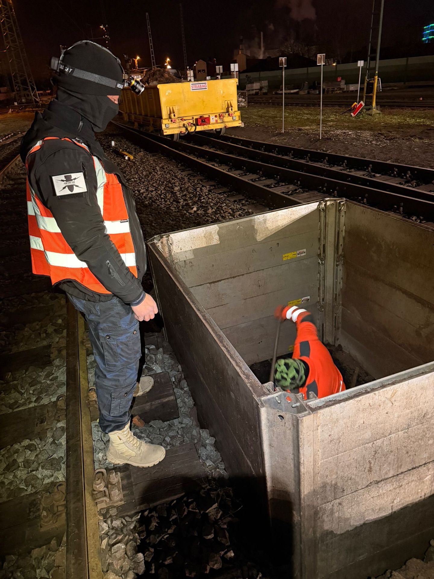
Assess the overall project context, including track construction, stations, crossings, structures and other railway tasks.
Consider the railway project as a wholeAssess corridors with suspected ordnance and installation areas before designing individual points and cable routes.
Clarify historical suspicion indicatorsPlan mast, gantry, pile and borehole positions with suitable casing, survey lengths and investigation depths.
Prepare deep foundation pointsAssess the suitability and sequence of explosive ordnance surveying during construction for cable trenches and demolition zones.
Coordinate the technical scope of excavation sections
Assess confirmed finds, specialist work and regional handover responsibilities.
Clarify reporting and recovery arrangementsExplore point lists, service specifications, status tracking, quality control and project handover.
Prepare procurement and point records
Account for the project location, federal state and regional contacts when addressing finds and procedural questions.
Understand regional responsibilitiesHave mast lists, foundation data, cable alignments, construction dates and existing documents reviewed.
Enquire about a railway power project and submit documentsProvide the project location, railway line, chainage and current point identifiers. Submit the site drawing, foundation data and cable alignment together. Existing requirements must be clearly assigned to the relevant locations and construction sections.
A new point identifier or position must not inherit a neighbouring location's status without assessment. Compare the position, foundation size and depth with the volume actually investigated, and mark any additional investigation areas.
Check evidence against the interventionPoint-specific foundation records do not automatically cover the adjoining cable trench. Both working volumes are recorded with their own geometry and depth; shared documentation makes these differences clear.
Explore the technical principlesTechnical information
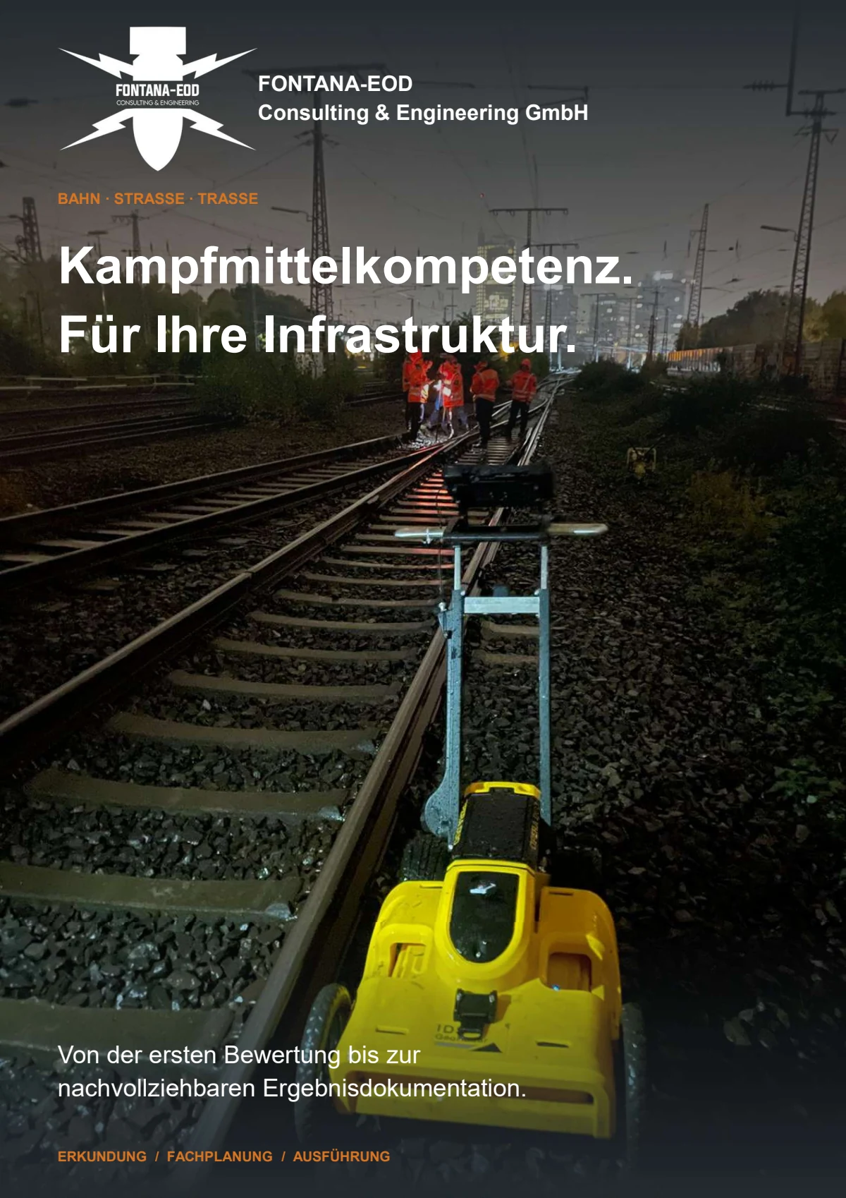
The brochure shows how FONTANA-EOD combines historical investigation, specialist planning, surveying and construction supervision in infrastructure projects. It explains trackside constraints, method selection and limitations, and result documentation.
It becomes relevant when mast foundations, gantries, switching or feeder installations, cable routes, earthing installations, excavations or demolition affect ground with suspected ordnance or ground that has not been adequately assessed. The technical assessment should be complete before tendering and, at the latest, before the relevant foundation or cable installation is constructed.
Current site drawings are required showing the railway line, track, kilometre reference or chainage, mast or point numbers, coordinates, foundation type, dimensions, design depth, construction or installation method and existing utilities. Overhead line, earthing and cable drawings, ground investigation data, historical assessments, previous survey reports, construction time windows and the required records are also helpful.
Official information and requirements are included with complete appendices, dates and spatial scope. In Germany, the relevant ordnance disposal service and local public order authority are identified for the project location; operational switching and work authorisations remain separate processes. Outside Germany, coordination is with the authorities responsible locally.
Not automatically. A mast foundation, gantry support or deep cable structure affects a defined point and depth volume. A near-surface survey can assess the surroundings but covers the entire foundation geometry only if the method, depth and spatial coverage demonstrably support that conclusion. A separate depth or borehole investigation is often required.
Metal installations, return-current and earthing systems, cables, masts, reinforcement and operating electrical equipment can alter the magnetic or electromagnetic survey environment. The effects depend on the method and operating conditions. Known installations, possible operational isolations, survey distances and alternative investigation approaches are therefore considered when selecting the method.
Each point receives a unique identifier with the railway line, track, chainage or coordinates, foundation type, design depth and drawing revision. Investigation depth, survey conditions, anomalies, limitations and follow-up measures are recorded for each point. A status list links individual points to the overall project and shows which locations have been investigated, remain outstanding, have been relocated or have been added.
The point is not automatically classified as being without anomalies. First, the assessment establishes whether revised drilling or survey geometry, an alternative point, another construction stage or a different method can still cover the required working volume. Any remaining gap is marked on the drawing and in the point status and assigned a specific follow-up measure before ground disturbance.
The suitability of explosive ordnance surveying during construction is assessed for cable trenches, demolition excavations and switching installation areas. Each working layer is surveyed and assessed by a specialist before removal. Controlled excavation in layers and an additional visual inspection follow; these steps are repeated to the agreed base of excavation. Excavation layers, working areas, equipment operation, stop points, channels for issuing instructions and documentation are agreed before work begins. For deep mast or pile foundations, this does not automatically replace the required point-specific depth investigation.
If an unexpected suspicious object is found, stop work. Do not touch, move or uncover it further. Leave the immediate area and warn others without putting yourself at risk. In Germany, notify the police on 110; outside Germany, use the local emergency reporting procedure. The competent authorities determine what happens next; a project enquiry does not replace reporting the find.
Key factors are the number, location and depth of mast and foundation points, cable route lengths, foundation and construction methods, existing utilities and installations, interference, access, possessions and electrical switching windows, surveying required, number of mobilisations, data quality and documentation requirements. A reliable estimate requires a consistent point list and set of drawings.
Describe the location and depth of mast foundations and cable trenches, the construction method and the records required. A mast count alone is insufficient for a technical assessment.
Incomplete designs can be reviewed early. However, agreed coordinates, design depths, foundation types and drawing revisions are required before fieldwork.
For construction programmes covering several railway sections, also provide priorities, work-package boundaries and firm construction dates. This helps distinguish mast and cable points needed early from later design options, and align mobilisation, interpretation and data handover with the actual construction sequence.
Provide the railway line, track, kilometre reference or chainage, mast and gantry numbers, coordinates, foundation types, switching or feeder points and current drawing revisions.
Clearly identify deleted, relocated and additional positions.
Describe foundation dimensions, design depths, drilling, driving or excavation methods, cable alignments, trench depths, chambers, crossings and demolition work.
Equipment setup and the working volumes required can also be relevant to the investigation design.
Include utility, earthing, overhead line and as-built drawings, ground investigation data, historical assessments and earlier reports.
State possession or electrical switching windows, construction stages, priorities and the intended use of the documentation.
For an initial assessment, a site drawing, mast or point list, foundation dimensions and depths, cable alignments, planned dates and existing evidence of ordnance are often sufficient. FONTANA-EOD uses these to assess which locations need depth investigation, area surveys or investigation during construction.
For large programmes, the enquiry can be divided by construction section and priority. Mast positions needed early and time-critical cable areas can then be addressed separately from later locations whose designs are not yet agreed.
Mast, gantry, switching point, coordinates, chainage and drawing revision.
Foundation type, diameter, design depth, drilling or installation method.
Utilities, earthing systems, rails, installations, access and operating conditions.
Design, tendering, site management, construction or the project file.
Whether historical aerial photograph analysis, explosive ordnance surveying, surface surveying using GPR, magnetometry or TDEM, deep-ground surveys, downhole surveys, excavation supervision, area clearance or ordnance recovery is needed depends on the location, ground disturbance, depth, ground and existing documents. An early ordnance assessment provides clarity for tendering, programming, occupational safety and construction.
FONTANA-EOD combines its Section 7 SprengG licence, specialists holding Section 20 SprengG certificates of competence, suitable survey and clearance methods, and traceable documentation. Send the site plan, depth of ground disturbance, construction phase and existing documents for an initial technical assessment.


