Project pathway
The quickest route to the right decision.
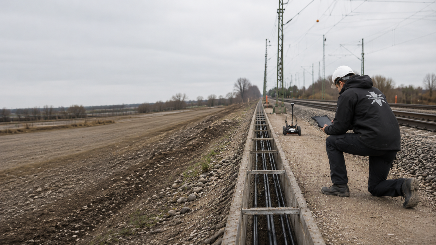
At level crossings and utility crossings, railway, road and utility organisations must coordinate explosive ordnance investigation across several working volumes. Launch and reception pits, open crossing areas and the underground alignment each need their own position and depth references. Submit the crossing drawing, records of suspected explosive ordnance and construction method to FONTANA-EOD so that the required investigations can be specified before excavation, drilling or tunnelling.
Establish the alignment, pits and depth profile.
Identify tracks, roads and utilities.
Document investigation volumes and limits.
For railway crossings, launch and reception pits, the route and the deep working volume must be assessed separately. Ordnance evidence, utilities and existing railway installations affect the investigation options.
An area survey does not automatically cover deeper crossing volumes. The investigation concept must cover the actual planned alignment, geometry and depth of ground disturbance.
Explosive ordnance surveying was carried out at Bad Dürkheim level crossing. When preparing further projects, the crossing area, depth of ground disturbance and construction stages must be clearly defined. View project details.
Service areas:Surface surveys: GPR, TDEM and magnetometry
A level crossing, open-cut utility crossing, launch pit, reception pit and underground drive are technically distinct working volumes.
Explosive ordnance investigation is structured so that each ground disturbance can be assessed by its own location, depth and construction stage.
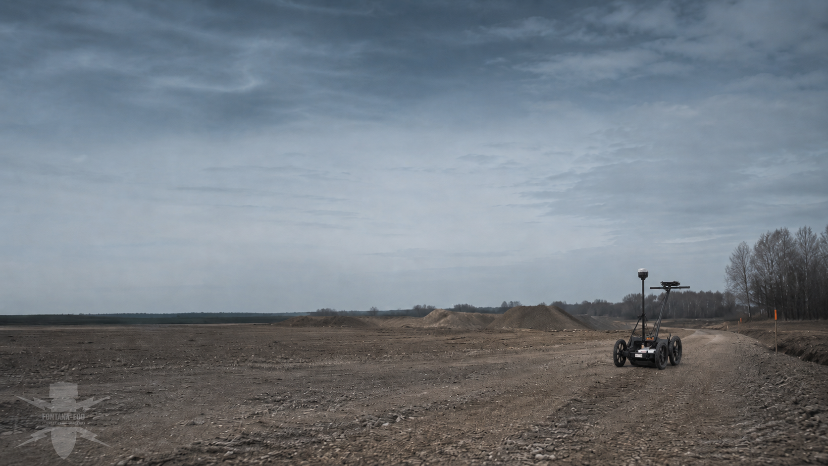
Road surfacing, track infill, drainage, cables, foundations and traffic management involve several ground disturbances at different stages. Explosive ordnance investigation is related to the carriageway, track zone, adjoining areas and construction stages.
Demolition stages and inaccessible subareas are defined as separate investigation stages before work begins.
Prepare the technical scope for a level crossing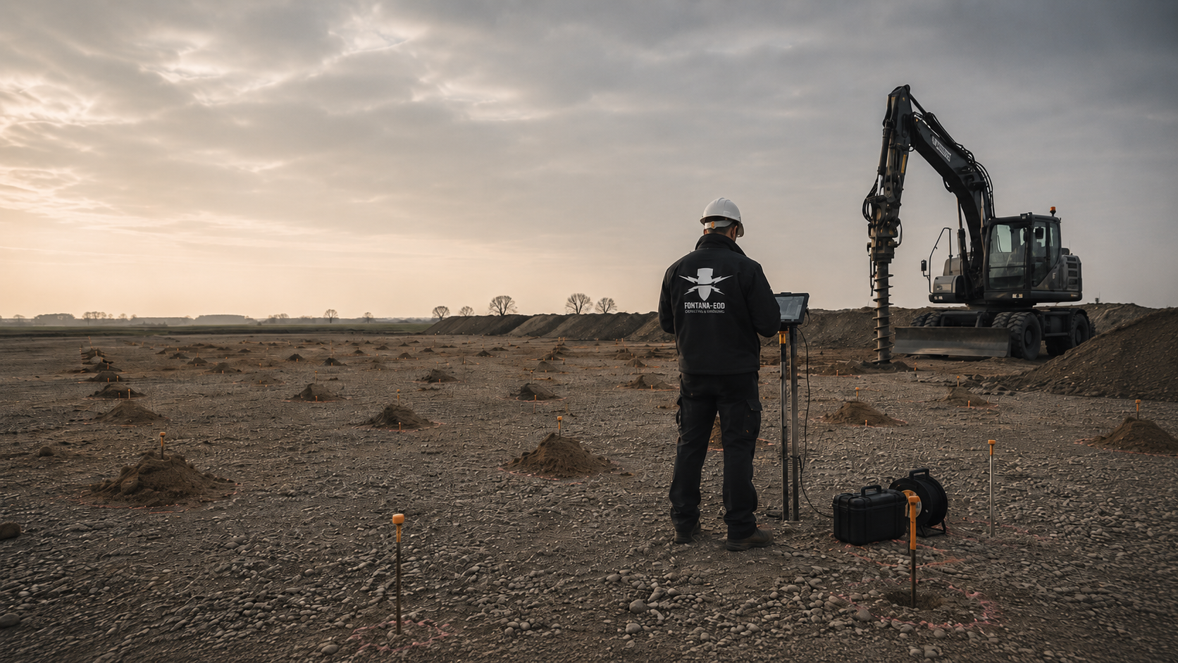
Pits for jacking, drilling or tunnelling require investigation of both area and depth, including excavation support, the working volume and the eventual base of excavation.
Utilities, traffic, proximity to tracks and excavation support are considered when selecting methods and organising work.
Investigate pits and depth volumesDrilling and tunnelling alignments run beneath tracks or railway installations and may lie below the effective depth of a surface survey. The alignment, depth profile, diameter and method therefore define their own investigation geometry.
The launch area, reception area and underground corridor are not covered by a single general conclusion.
Assess the crossing alignment and depth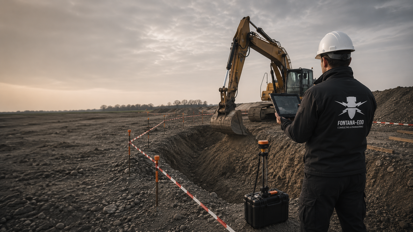
In open-cut construction, the road structure, track area and utility trench are exposed section by section. Surveying and investigation during construction must match the excavation width, depth stages and traffic phases.
Each subarea receives a clear investigation and handover status.
Coordinate the technical scope of open excavationCulvert construction, chambers, trenches and pipe connections link linear alignments with deeper excavations and existing structures. Foundations, reinforcement and water conditions can affect survey feasibility.
Open approaches, structural zones and deep points are planned separately.
Investigate culvert and drainage areas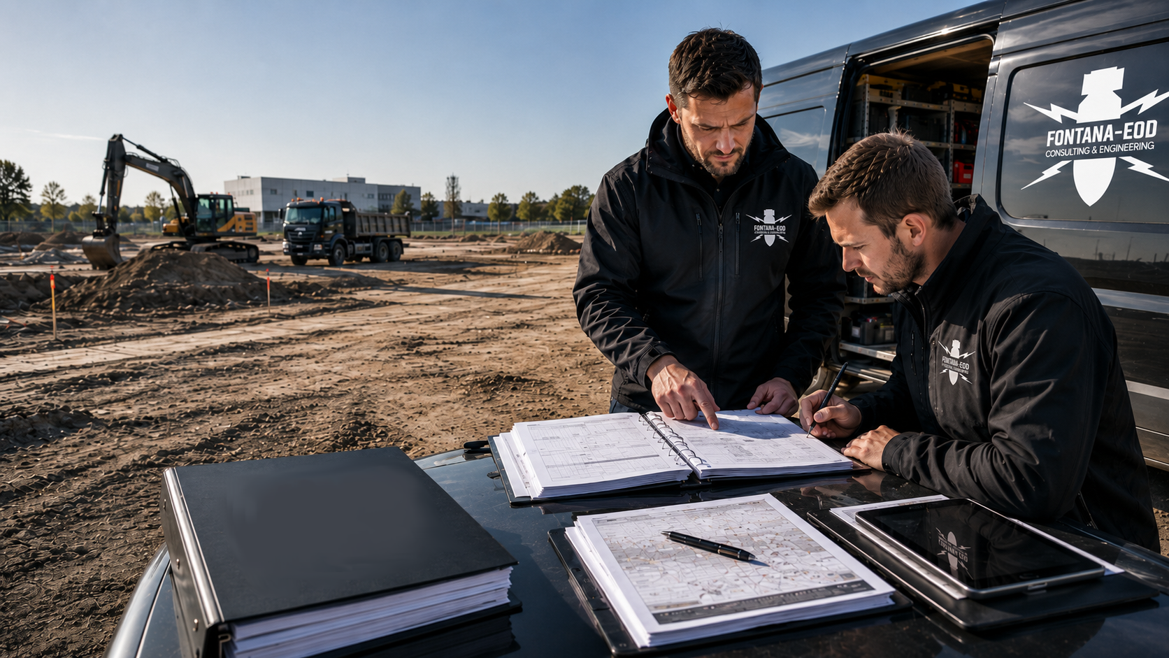
Level crossings and utility crossings often involve several organisations responsible for land, operators and traffic phases. A common site drawing shows where the working areas of different contractors or operators meet.
Drawing revisions, handovers and unresolved areas use the same crossing identifier.
Define interfaces and handoversSeveral cables or pipes may share protective ducts or closely spaced corridors. For explosive ordnance investigation, the launch and reception pits, individual alignments, depths and possible enlargements must still be clearly described.
Changes in grouping, diameter or driving sequence are checked against the existing investigated working volume before construction.
Define the technical limits of the utility corridorThe investigation sequence depends on whether the outstanding issue concerns historical ordnance, the crossing geometry, method suitability or the construction sequence. Designers must be able to see which information is already established and which is missing.
Before ground disturbance in the carriageway, track area, launch and reception pits or underground crossing corridor, the available evidence of ordnance must be clarified. This establishes the investigation requirements for the planned areas and depths.
Route options, crossing angles, launch and reception areas and anticipated depths are compared with historical documents and as-built information.
The result identifies which option creates additional investigation requirements and which information is missing before detailed design.
Assess the corridor with suspected ordnance during preliminary designOpen-cut construction, jacking, directional drilling and other trenchless methods affect different working volumes. Before explosive ordnance investigation is designed, the geometry of the actual ground disturbance must be clear.
Options are compared according to achievable investigation depth and follow-up measures.
Coordinate the construction method and investigation volumeOnce pit dimensions, depths to the excavation base and excavation support are known, area and depth investigation services can be clearly specified.
Access routes, working platforms and inaccessible adjoining zones are included in the investigation design.
Check pit geometry and depthCables, pipes, rails, foundations, earthing systems and reinforcement can obscure survey data. Existing installations are mapped before method selection.
Areas where data cannot be reliably interpreted are marked on the drawing. Before ground disturbance, the further investigation that is possible and required is assessed.
Assess interference and survey methodsWhere ground is exposed section by section, explosive ordnance investigation must match the excavation sequence, traffic management and time available.
Excavation layers, stop points and handovers are agreed and described before work begins.
Coordinate excavation and traffic phasesThe road authority, railway infrastructure organisation, utility owner, designers and contractors need the same spatial basis.
Reports and drawings distinguish investigated zones, unresolved points and conditions for the next construction section.
Define a common structure for the investigation recordsIf the exact position within a tolerance corridor is still undecided, explosive ordnance investigation must consider the possible working volume rather than just a theoretical centre line. Depth, steering capability and permitted deviations are checked against the proposed investigation geometry.
Before construction begins, the design alignment is developed into a clearly defined construction basis that can be technically assessed.
Define the tolerance corridor and investigation volumeA crossing comprises several technical volumes. The surface, pits and underground alignment are therefore described with their respective depths and access arrangements. This forms the basis for selecting investigation methods.
Existing utilities, rails, reinforcement, foundations and earlier excavations affect geophysical investigation. For inaccessible sections or those affected by technical interference, the further measures that will cover the planned ground disturbance are assessed before construction. Investigation during construction is considered only where technically suitable.
Trigger: Aerial photographs, known finds or previous land use indicate possible ordnance around the crossing.
Technical step: Areas with suspected ordnance are compared with the road surface, track zone, pits and alignment corridor.
Required outcome: Spatially justified technical investigation areas and identified data gaps.
Clarify the spatial scope of the historical evidenceTrigger: The launch pit, reception pit or shaft has a defined area, base and excavation support.
Technical step: Near-surface and deep investigation volumes are matched to the excavation geometry and sequence.
Required outcome: A clear investigation status for the actual pit volume.
Define the pit volume and investigation depthTrigger: The drive or bore runs at greater depth beneath tracks and traffic areas.
Technical step: The alignment, depth profile, diameter and tolerance envelope are assessed against technically achievable investigation methods.
Required outcome: A clear distinction between alignment sections already covered and those still requiring investigation or protective measures.
Assess the underground corridorTrigger: Carriageway, track or adjoining surfaces are removed by open-cut methods or shallow excavation.
Technical step: Suitable surface methods are selected according to the target object, surface and interference.
Required outcome: Survey areas, anomalies and limitations recorded with geographic coordinates for the defined working volume.
Investigate the crossing areaTrigger: Existing utilities, reinforcement or installations obscure the survey data.
Technical step: The zone is marked on the drawing. The assessment then establishes whether it can be investigated after demolition, through a depth investigation or by suitable investigation during construction.
Required outcome: No remaining area left unrecorded at the interface.
Plan follow-up measures for interference zonesTrigger: The crossing angle, depth, launch point, reception point or pit dimensions change after investigation.
Technical step: The new drawing revision is checked against the survey and point geometry.
Required outcome: A reliable assessment of which results remain applicable and where additional investigation is required.
Check the design change against the available evidenceTrigger: Cables, water, gas, drainage or control lines are installed along separate alignments and at different construction stages.
Technical step: Each crossing has its own identifier; common as-built information and ordnance evidence are managed centrally, while pits, alignments and depths are assessed separately.
Required outcome: Comparable investigation statuses for each crossing geometry, kept distinct from one another.
Structure the crossing programme and recordsUsable records must show the crossing geometry as clearly as the survey conditions and results.
Drawings and survey data must identify which information relates to the pits, surface areas and underground alignment.
The records link the alignment, depth profile, pit geometry, methods, results and limitations. This allows project management to see which parts were investigated and what remains to be clarified before the next construction section.
The railway line, track, road alignment, kilometre reference or chainage, crossing angle, launch and reception points, and coordinate system establish the spatial basis.
Each pit, survey area and alignment receives a unique identifier.
Pit dimensions, depths to the excavation base, excavation support, drilling or drive alignment, diameter, cover and tolerance envelope are assigned to the planned construction method.
Changes are recorded with the drawing revision.
Historical assessments, utility drawings, structures, earlier excavations, known finds and official documents are recorded with their spatial scope.
Unclear or contradictory data remain explicitly identified.
Survey lines, grids, borehole positions, investigation depths, raw data, interpretation and field conditions are linked to the crossing and pits through common identifiers.
Areas not reached are explicitly identified.
Anomalies are recorded with their position, depth, assessment status and planned follow-up measure.
A survey anomaly, an object causing technical interference, an exposed object and a confirmed find are recorded as distinct categories.
The report describes which subvolumes were investigated, which methods were used and which limitations remain. Where suspected points are exposed or areas are cleared, the findings and clearance records for the work actually carried out are added with clear position and depth references.
Road, railway and utility participants can identify the conditions for the next construction or authorisation step.
For steered or jacked crossings, the planned alignment and the installed route may differ. Where required for the project decision, the as-built position, depth profile and range of deviation are included in the final documents.
This allows subsequent assessment to refer to the work actually carried out rather than just the design geometry.
Before the crossing is constructed, the alignment, pits, depths to the excavation base, excavation support, diameter and tolerance envelope are compared with the underlying explosive ordnance investigation. Deviations arising from approval conditions, utility redesign or construction-related relocations are recorded spatially.
This keeps it clear whether the existing survey and investigation data cover the actual working volume used during construction.
The project file contains the ordnance evidence, crossing drawing, investigation results and outstanding tasks.
This allows the client and site management to trace the investigation status even when construction stages or designs change.
Aerial photographs, maps, statements, reports of finds and earlier project documents are related to the crossing area and route corridor.
The dataset identifies which assumptions about possible ordnance trigger technical investigations.
Launch pits, reception pits, shafts, open construction sections and the underground alignment are recorded with their depth profile and drawing revision.
This keeps the actual construction geometry traceable through design options and revisions.
Cables, pipes, drainage, rails, foundations, reinforcement and known objects causing interference are recorded with their source and positional accuracy.
They provide a reference for method selection and data interpretation.
Survey lines, grids, boreholes, investigation depths, raw data and assessments are assigned to the relevant subvolumes of the crossing.
Deviations and zones not reached remain in the register.
Each relevant anomaly has an identifier, location, assessment status, action pathway and result.
Outstanding issues are not concealed by a general completion statement.
Reports, drawings, field logs and decisions are brought together for the client and the railway, road and utility interfaces. Findings and clearance records are added where the corresponding exposure or clearance work has actually been carried out.
The handover states the investigation status reached and outstanding tasks for each subvolume.
Rejected and approved alignments, revised pit locations and adjusted depth profiles are recorded with their dates and drawing status. The register prevents surveys or assessments from being inadvertently applied to a crossing option that is no longer valid.
This also allows additional investigation requirements arising from contract variations to be clearly defined.
Each step resolves a defined part of the project. The sequence is adapted to the design stage, construction method, possession phases and accessible working volumes.
In multi-stage approval and construction processes, the required investigations are scheduled before the relevant ground disturbance. Surveying, pit construction, the drive, utility installation and surface reinstatement have clear handover points. Changes to the alignment, method or construction stage are checked against the documented investigation volume before the next ground disturbance.
The level crossing, open-cut crossing, launch and reception pits, drive alignment, construction method, depths and assessment required are clearly described.
Historical assessments, railway and road drawings, utilities, structures and previous investigations are related to the same drawing revision.
Areas with suspected ordnance are compared with the pits, affected surface areas and underground alignment corridor.
Surface surveys, depth investigations, access at later stages and excavation monitoring are planned separately and coordinated.
The alignment, pits, survey lines, borehole positions, traffic phases, possessions and stop points are agreed before work begins.
Technical investigation and fieldwork take place within the documented geometry; changes are assessed immediately.
Survey readings, existing structures, anomalies and areas where data cannot be interpreted are related to the planned ground disturbance.
The report, drawings, outstanding measures and conditions for drilling, tunnelling or excavation are handed over to the project participants.
The individual working volumes are assessed separately: open pits, near-surface road and track areas, deep drilling or drive alignments, and excavations for shafts and excavation supports. Survey feasibility and required investigation depths differ between them.
Launch and reception pits can be investigated using surface and depth methods, while the drive corridor between them often lies considerably deeper. A successful investigation of the pits therefore does not automatically answer the question along the alignment.
In open-cut construction, demolition and traffic phases change the area available for investigation. For zones affected by technical interference, the possibility and timing of investigation later in the construction sequence are assessed. Until then, they remain marked as not fully investigated.
The final conclusion brings together the investigation status of the individual areas. It identifies the subvolumes covered, survey limitations and further measures required, without exceeding the scope of each method.
Pits are described by area, excavation base, slopes or excavation support, and working volume.
The investigation covers the actual excavation and support volume rather than just the centre of the pit.
The drilling or drive alignment, depth profile, diameter and tolerance envelope define a separate corridor.
Its investigation geometry cannot be inferred from the work at the two pits.
The carriageway, track area and adjoining surfaces may be removed over several construction stages.
Surveying and excavation monitoring are related to the area exposed and excavation depth at each stage.
Cables, pipes, foundations, reinforcement and rails affect survey data and equipment access.
Known installations are recorded as references; zones that cannot be resolved are assigned their own follow-up measure.
Surface methods have a project-dependent investigation depth range.
If this does not reach the alignment, pit base or excavation-support geometry, suitable additional services address the missing depth volume.
If the crossing angle, alignment, pit location or depth changes, the new working volume is checked against the documented investigation volume.
Partial handovers clearly state which geometry was investigated and which points remain unresolved.
The volume affected by the construction method may extend beyond the pipe or cable diameter alone. The drill head, enlargement, steering movements, drive head and permitted deviations are therefore considered when defining the relevant corridor.
The explosive ordnance assessment remains tied to the volume actually defined and investigated.
In trenchless methods, the volume affected can change with pilot drilling, enlargement stages, curve radii and level corrections. These geometries cannot be represented by a simple line connecting the launch and reception points.
The technical design considers the possible spatial corridor and establishes which areas can be reached by investigation. If any subvolume remains outside reliable investigation coverage, the additional investigations required and the next steps are clarified before pilot drilling, enlargement or tunnelling begins there.

The historical evidence must cover the launch and reception areas and the corridor between them. Existing documents are compared with the actual planned alignment; a change in position may affect different areas with suspected ordnance.
Assess the basis for suspicionInvestigation of the ground surface does not automatically describe the deeper drilling or drive volume. The volumes that can be surveyed and the remaining limitations are defined separately for pits, shafts and the crossing alignment.
Assess depth-related investigationThe methods are neither equivalent nor freely interchangeable. They are combined according to the target object, depth, surface, technical interference and subsequent construction method.
Establishes areas with suspected ordnance around the crossing and along the proposed route.
It does not detect individual objects present today and replaces neither investigation of the pits nor investigation of the alignment.
Detects ferromagnetic anomalies in areas with sufficiently low interference.
Rails, utilities and metal structures can limit survey feasibility at a level crossing.
Responds to the electromagnetic properties of conductive objects and can provide additional investigation of certain areas.
Suitability and effective investigation range depend on the target object, ground conditions and technical surroundings.
Shows reflections at material and structural boundaries and can supplement investigation in paved areas or areas with magnetic interference.
A reflection is not conclusive identification of ordnance; the depth supported by the data must match the planned ground disturbance.
Investigates defined deep points and corridors for pits, excavation supports or boreholes.
The borehole point geometry and future crossing alignment must be spatially coordinated.
In suitable open excavation areas, each working layer is surveyed and assessed by a specialist. This is followed by controlled excavation in layers and an additional visual inspection. These steps are repeated to the agreed base of excavation; visual inspection of the excavator's work alone is insufficient.
The investigation applies to the layers covered and does not cover an underground drive that has not been investigated.
Targeted exposure can clarify individual anomalies in launch pits, reception pits or open excavations where the working volume, excavation support, dewatering and safety arrangements allow.
The finding applies to the point or section investigated. The underground crossing alignment and adjoining areas not exposed still need their own investigation and supporting records.
The crossing drawing must show the positions of pits, alignments and working areas, and the depths of the work. Methods, construction stages and documentation are coordinated on that basis.
Site management must be able to see survey results, areas not investigated and further tasks together.
FONTANA-EOD starts by distinguishing the surface, open pits and underground alignment. This prevents an easily accessible subarea from being treated as a substitute for the entire crossing volume.
Existing utilities and structures are checked against the survey objective and equipment access before fieldwork. Where a method has technical limitations, additional investigation is planned before tunnelling or excavation begins.
The handover to designers and site management shows the assessment available for each subvolume, the conditions that apply and where a follow-up measure is still required.
The alignment, pits, shafts and open sections are linked through the drawing revision and common references.
The investigation approach and documentation of results are defined separately for the surface, pits and underground corridor.
Utilities, rails, structures and previous excavations are considered as technical constraints.
Access, possessions, demolition, excavation and tunnelling are coordinated with the specialist services required.
Areas where data cannot be interpreted, areas that are inaccessible and areas outside the investigation range remain identified.
Design changes and additional construction sections are assessed against the existing investigation status.
Launch and reception pits become accessible at different times. The sequence must identify which investigations are possible before and after that access becomes available, and which results are needed before the next ground disturbance.
The investigation records must use the same drawing revision as the construction work. Investigated pits, depths covered and unresolved areas are identified so that any later change in alignment or depth can be recognised as potentially outside the previous scope.
Level crossings and utility crossings bring together several areas of infrastructure and responsibility. Designers, site management and the specialist contractor must use the same drawing revision and know who can authorise changes or stop work.
Define the project objective, crossing volume, assessment required and priorities. Where several ownership or operating boundaries are involved, they establish a common drawing and data basis.
Defines the crossing alignment, pits, depth profile, construction method, existing utilities and construction stages, and incorporates explosive ordnance investigation into the design and bill of quantities.
Sets requirements for access, possessions, traffic phases, protection zones and operational working conditions. These arrangements are coordinated with the fieldwork.
Constructs pits, excavation support, excavations, boreholes or drives in accordance with the agreed drawing and reports changes in position, depth or method.
Reviews documents, develops the agreed approach, carries out specialist services and documents results, limitations and follow-up decisions.
In Germany, the ordnance disposal services of the federal states and the locally competent authorities carry out hazard-response and find-management duties. Their involvement is established for the project location; outside Germany, local responsibilities apply.
The local public order authority and building control may be involved, depending on local procedures and the construction task. Their requirements are recorded with the location, section and current drawing revision. Technical investigation, operational authorisation and official decisions about finds remain documented with their respective contacts.
Establishes common positional references for the crossing alignment, pits, survey lines, borehole positions, existing utilities and as-built route.
Revision data are recorded so that the design alignment, investigated volume and actual construction can be technically compared.
Requirements depend on the activity, project location, infrastructure operator, construction method and finds. The service specification, risk assessment and chain of responsibility are related to the specific commission.
In Germany, § 7 SprengG concerns the commercial authorisation for activities requiring authorisation; § 20 SprengG concerns the certificate of competence of responsible persons. Under § 1b SprengG, searching for found munitions also counts as handling them. The requirements applicable to the project depend on the activity actually commissioned.
DGUV Information 201-027 supports risk assessment and the definition of protective measures for ordnance clearance work. The Baufachliche Richtlinien Kampfmittelräumung set requirements for investigation, design, quality and documentation within their defined scope of federal responsibilities. Their application to the specific crossing project is clarified separately.
Railway, road and utility requirements additionally govern access, operations and technical interfaces. They do not replace the specialist explosive ordnance assessment or the regional allocation of responsibilities when ordnance is found.
The First Ordinance to the German Explosives Act (1. SprengV) includes requirements for specialist competence and state-recognised training courses. At level crossings and utility crossings, the qualifications of the responsible personnel are matched to the actual commissioned scope of work.
DGUV Rule 113-003 concerns the dismantling or destruction of explosives or articles containing them and also includes the disposal of munitions finds. Its application depends on that scope of activity; the project-specific risk assessment remains focused on the pits, crossing alignment and planned ground disturbance.
The scope of work, company, formal appointment and competence must suit the specific commission and any findings that may need to be addressed.
Excavations, traffic areas, the track environment, equipment, personnel, protection zones, escape routes and reporting chains are considered together.
Pits, the alignment, depth volumes, methods, quality requirements and acceptance criteria are clearly specified.
Site management, the project sponsor, specialist contractor and competent authorities follow a communication procedure agreed in advance.
The drawing revision, crossing geometry, construction method, ownership and operator boundaries, and required records are clarified.
All participants must know the responsible personnel, protection zones, stop points, design changes and handover arrangements.
Stop work in the affected area immediately. Do not touch or move the object. Leave the danger area and keep others away without putting yourself at risk. In Germany, contact the police immediately on 110; outside Germany, use the local emergency reporting procedure.
The project file distinguishes the crossing's subvolumes while linking them through the same drawing revision and identifier system. This keeps handovers and changes traceable.
For several crossings, an overall status list supports coordination: for each alignment, it states the drawing revision, investigation scope, unresolved subvolumes, next measure and responsible interface.
Shows the railway and road alignments, launch and reception pits, shafts, open construction sections, underground alignment and depth profile.
Each area has its own investigation status.
Document the subvolumes of the crossingRecords utilities, cables, foundations, rails, reinforcement, earlier excavations and technical installations as known constraints.
Positional accuracy and data sources remain clear.
Document as-built data and constraintsLinks survey lines, grids, borehole positions, investigation depths and interpretation to the pits and crossing alignment.
Points not reached or relocated are recorded so that their status remains traceable.
Plan deep ground disturbance and survey points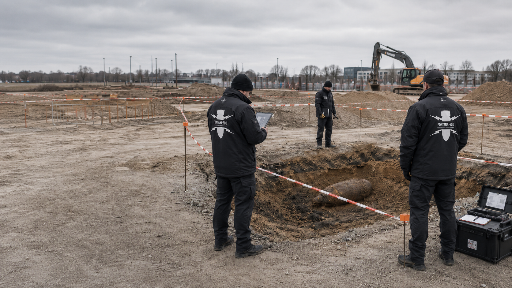
Organises anomalies by position, depth, assessment status and next technical step.
Survey anomalies and actual findings remain clearly distinguished.
Assign findings and further actionsDocuments excavation layers, the condition of excavation support, equipment use, stop points, observations and monitored subareas.
The conclusions are not extended to the underground drive.
Provide specialist support for pits and excavationBrings together the initial conditions, crossing geometry, services, results, limitations and follow-up decisions.
Railway, road and utility participants can then work from the same spatial basis.
Bring completion documents togetherSummarises the investigated pits, assessed alignment corridor, unresolved subvolumes, drawing revisions and conditions for the next construction step.
The status allows railway, road and utility participants to coordinate, without replacing specialist reports with simplified general statements.
Review the crossing status and supporting documents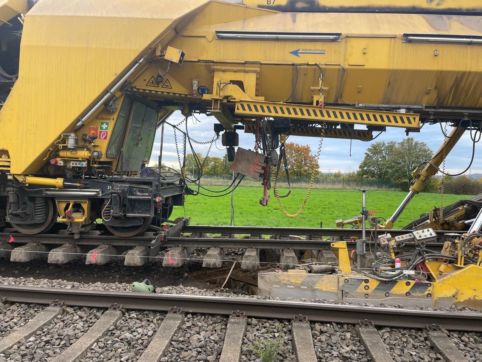
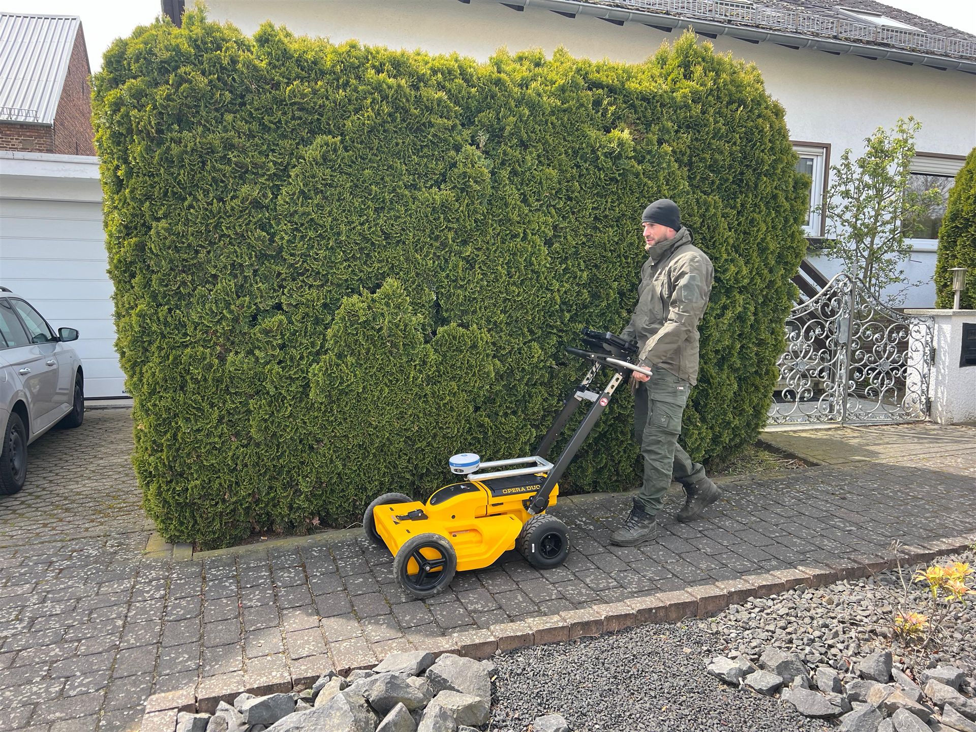
Coordinate railway tasks, construction stages and responsibilities.
Assess the railway project in its overall contextAddress the additional technical requirements of the track zone, track superstructure, cable routes and adjoining construction sections.
Prepare track construction and track superstructure renewalEstablish the spatial basis for suspected ordnance in the crossing area, pits and route corridor.
Clarify historical suspicion indicators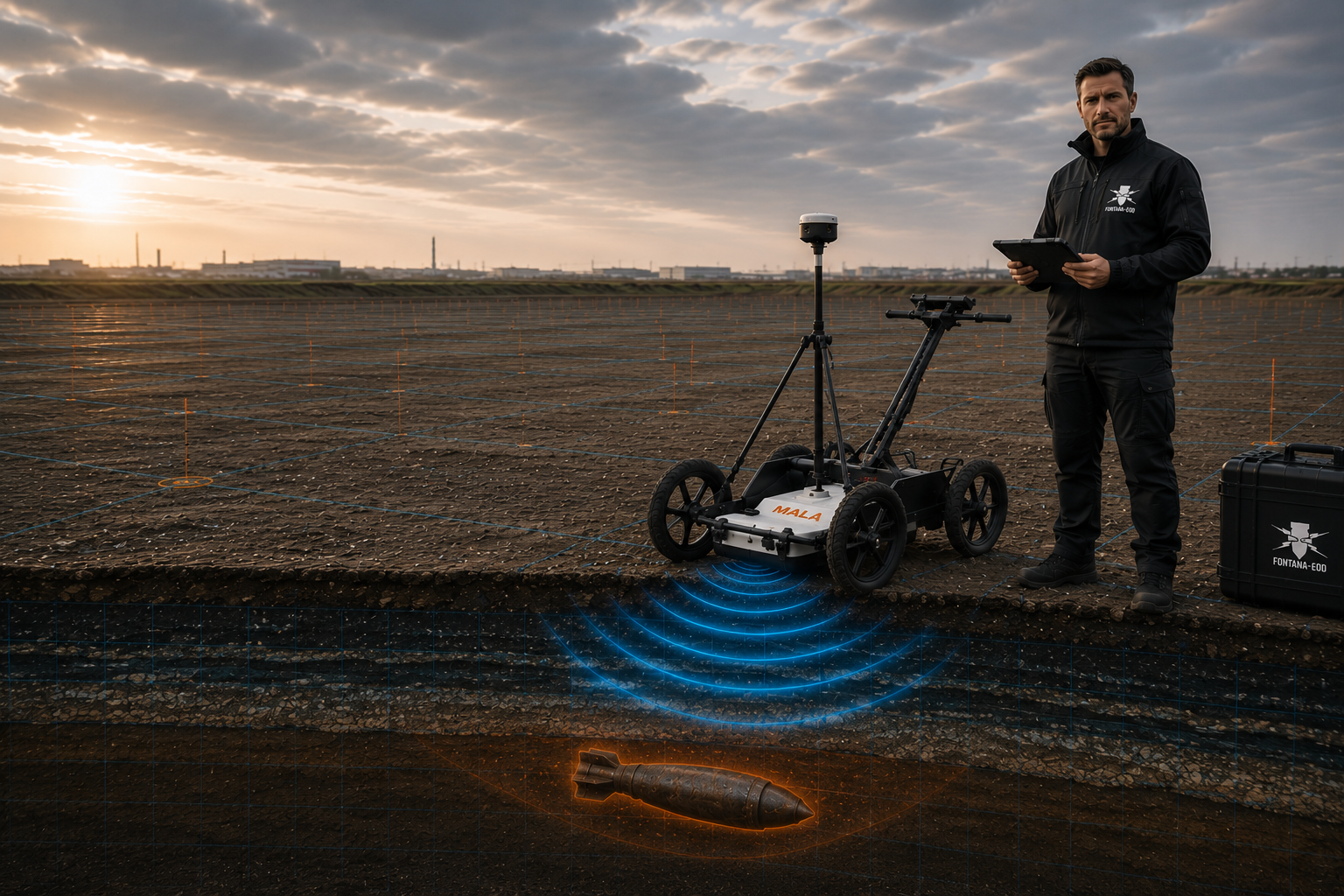
Select area survey methods according to the target object, surface, interference and depth supported by the data.
Select suitable surface survey methodsPrepare pits, excavation supports, shafts and deep crossing volumes with their own investigation geometry.
Investigate deep crossing volumesAssess the suitability and sequence of explosive ordnance surveying during construction for open excavation areas.
Provide specialist support for excavation and pitsCoordinate procurement, data structure, quality, handovers and final documentation.
Plan crossing records and handoversHave the crossing alignment, pits, construction method, depths and as-built documents technically reviewed.
Enquire about a crossing project and submit documents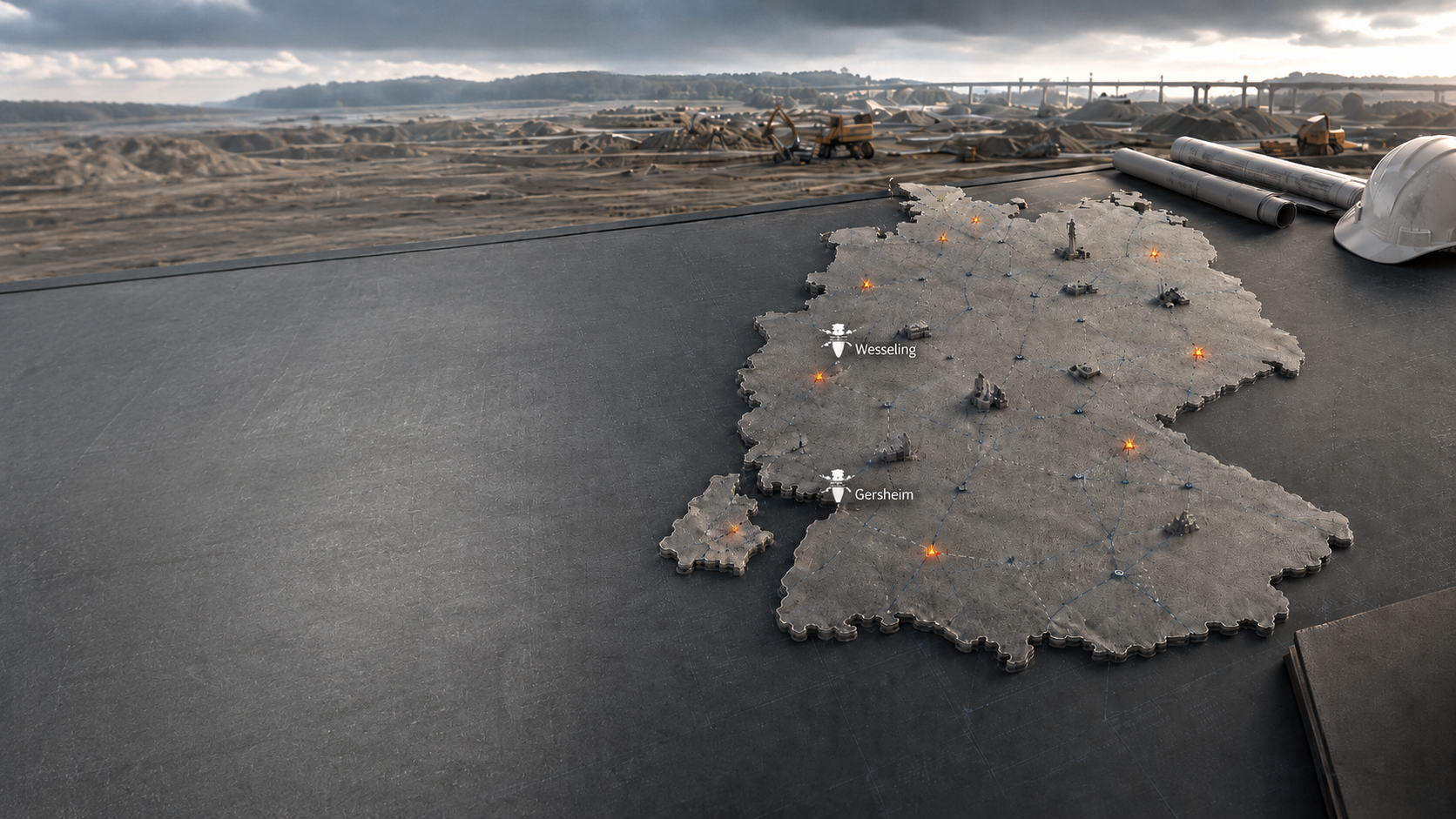
Provide the project location, railway line, chainage and launch and reception pit locations. Add the depth profile to the site drawing. Road connections, adjoining construction areas and existing requirements should be included with their spatial references.
The site drawing alone does not show every change in depth. Compare it with the current longitudinal section and pit geometries. The records must show which parts of the actual working volume have been covered.
Check evidence against the interventionRelocated pits, revised curve radii or greater depths may affect new areas. Before construction, existing results are checked for continued applicability and any additional investigation requirements are identified.
Explore the technical principlesTechnical information
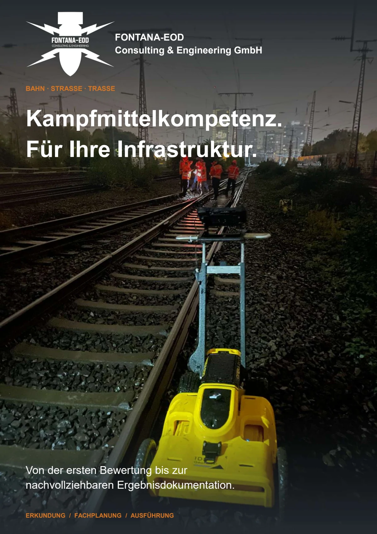
The brochure shows how FONTANA-EOD combines historical investigation, specialist planning, surveying and construction supervision in infrastructure projects. It explains trackside constraints, method selection and limitations, and result documentation.
When designs change, existing records are checked against the new alignment, depths and pits.
When making a follow-up enquiry, therefore state the drawing revision and any changes to pits, alignments, depths or construction stages.
A technical investigation becomes relevant when work on a carriageway, track crossing, launch or reception pit, pipe drive, cable crossing, drainage or other ground disturbance is planned and the evidence of ordnance for that working volume has not been reliably assessed. The deciding factors are location, depth, construction method, construction stages and the assessment needed before procurement or construction.
Open excavations, launch and reception pits, drilling or drive alignments, surface areas, road connections and zones adjoining the railway have different depths and access conditions. They therefore have separate investigation geometries. Assessment of the pits or surface does not automatically cover the underground crossing route.
The required documents include a site drawing, railway and road references, kilometre reference or chainage, launch and reception points, the crossing alignment and depth, pit geometries, construction method, utility and as-built drawings, and existing aerial photograph assessments and previous investigations. Construction dates, traffic phases, possessions and the required records are also important.
Existing requirements and official information are submitted with all appendices, dates and spatial scope. In Germany, the involvement of the relevant KBD, KMBD or KRD and local public order authority is clarified for the project location; operational work authorisations remain separate. Outside Germany, coordination is with the authorities responsible locally.
Launch and reception pits are planned as open ground disturbances; the underground alignment is described by position, depth profile, diameter, method and tolerance envelope. The assessment then establishes which sections can be reached by surface or depth investigation. Areas not adequately covered need suitable additional investigation or a technically agreed change in the construction sequence before the relevant ground disturbance. This applies before pilot drilling and enlargement as well. Monitoring open excavation does not automatically cover the underground alignment.
GPR provides reflection data within the demonstrated investigation zone. Its conclusions depend on the ground, moisture, track or road structure, utilities, survey-line layout and data quality. Deep alignment sections and zones shielded by technical installations are not automatically covered. They may require other geophysical methods, depth investigations or revised construction sequences.
It is considered where launch or reception pits, bore paths, jacking pits, shafts, excavation supports or foundations extend below the reliable investigation zone of a surface survey. The investigation geometry is related to the alignment, design depth, diameter and actual working volume. A point investigation does not apply to adjoining zones that were not covered.
Existing utilities, cables, pipes, rails, reinforcement and foundations are identified from drawings, utility detection and site inspection and considered during method selection. They can obscure survey data while also serving as useful reference structures. Areas where data cannot be interpreted conclusively are mapped and are not classified as being without anomalies.
If an unexpected object suspected of being ammunition is encountered, work stops. Do not touch it, move it or expose it further. Leave the immediate area and warn others without putting yourself at risk. In Germany, contact the police on 110; outside Germany, follow the local emergency reporting procedure. The competent authorities determine further action; a project enquiry does not replace reporting the find.
Key factors are the number and size of pits, crossing alignment length and depth, construction method, surfaces and ground conditions, existing utilities, interference, access, possessions and traffic phases, methods required, surveying and documentation requirements. A reliable estimate therefore requires clearly defined crossing geometry and a current drawing revision.
An enquiry should describe the crossing geometry rather than just identify a centre point. Launch and reception pits, open areas and the underground alignment are needed separately.
Early drawing revisions are also suitable if their approval status and outstanding design options are clear.
For several utility types or crossings constructed at different times, state the priority, approval status, operator responsibilities and planned sequence for each alignment. Also distinguish the agreed construction alignment, a reserved alternative corridor and a preferred option that has only been investigated. This allows explosive ordnance investigation to focus on the working volume actually anticipated, while later options remain clearly recorded as unresolved project decisions.
Temporary haul roads, assembly areas and equipment positions must also be included where they require their own ground disturbance or load transfer to greater depth.
Provide railway and road references, kilometre reference or chainage, crossing angle, launch and reception points, pit dimensions, shafts and open construction sections.
Where there are options, show which alignment is agreed and which is an alternative.
Describe open-cut construction, jacking, tunnelling, directional drilling or another method, including alignment depth, diameter, tolerance envelope, excavation support and maximum excavation depth.
Construction and traffic phases affect when the investigation is scheduled.
Include utility and as-built drawings, historical assessments, previous survey reports, ground investigation data, reports of finds and official documents.
State whether the results are needed for design, tendering, site management or the start of drilling and excavation.
Mark where road surfaces, railway land, utility land and site setup areas meet or overlap. These boundaries affect access, the provision of documents, construction stages and handover of investigation records.
Where contracts are awarded separately, also show which work package is responsible for the launch pit, reception pit, drive, surface reinstatement and specialist monitoring.
For an initial assessment, a site drawing, crossing alignment, approximate depth profile, pit locations, construction method, existing utility drawings and ordnance evidence, and the planned dates are often sufficient.
FONTANA-EOD then identifies the additional information required and a suitable combination of historical assessment, surface surveys, depth investigation or investigation during construction.
Railway and road alignments, kilometre references, pits, shafts and working widths.
Alignment depths, pit bases, diameter, excavation support and proposed construction method.
Cables, pipes, drainage, foundations, rails, reinforcement and known objects causing interference.
Possessions and traffic phases, construction date, handover points and required records.
Whether historical aerial photograph analysis, explosive ordnance surveying, surface surveying using GPR, magnetometry or TDEM, deep-ground surveys, downhole surveys, excavation supervision, area clearance or ordnance recovery is needed depends on the location, ground disturbance, depth, ground and existing documents. An early ordnance assessment provides clarity for tendering, programming, occupational safety and construction.
FONTANA-EOD combines its Section 7 SprengG licence, specialists holding Section 20 SprengG certificates of competence, suitable survey and clearance methods, and traceable documentation. Send the site plan, depth of ground disturbance, construction phase and existing documents for an initial technical assessment.


