Project pathway
The quickest route to the right decision.
For station designers, site management and contractors, platform redevelopment involves different area and depth tasks: edges, lifts, stairs, ramps, utilities and roof foundations. FONTANA-EOD compares the ordnance evidence with these structures and the construction stages. Send station and ground-disturbance drawings so that suitable investigations and the required section records can be specified.
Identify the platform, access route and drawing revision.
Record areas, excavations and deep points.
Document investigation status for each construction stage.
For platform and station redevelopment, investigation requirements for edges, lifts, access routes, utilities and foundations are determined from the available ordnance evidence. The individual structure, its depth of ground disturbance and the construction stage at which the ground is accessible determine the approach. Suitable methods, unresolved areas and the section-specific records needed are specified before construction.
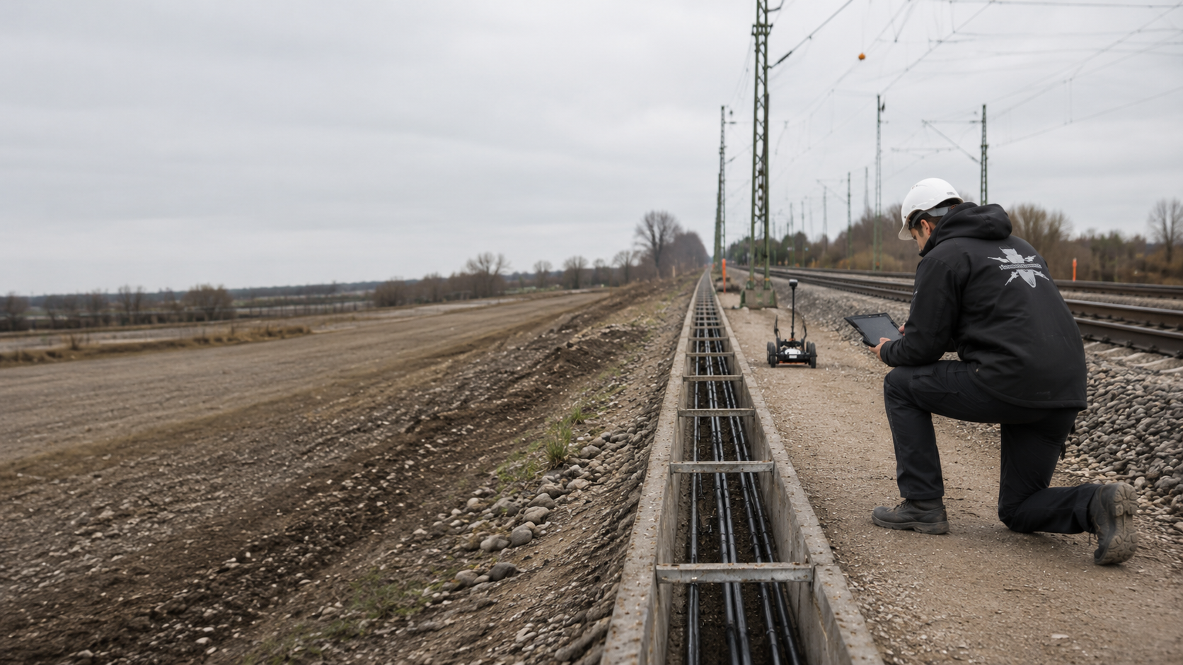
Ordnance monitoring during civil engineering work was carried out for the track and platform redevelopment at Hochspeyer station. View project details.
Service areas:Ordnance specialist supervision of groundworks
Borehole magnetometry, GPR and construction-stage monitoring are listed for Haan station in May 2026. The documented project context concerns the track and wall area. View project details.
Service areas:Ordnance specialist supervision of groundworksDownhole magnetometry / deep-ground surveySurface surveys: GPR, TDEM and magnetometryMethod used in this project: Ground-penetrating radarSetting out and marking survey areasDocumentation and interpretation of survey data
Platform redevelopment consists of several spatially and technically different ground disturbances. Investigation requirements are therefore divided not just by platform length but by structure, depth, construction stage and access.
For each structural area, ground-disturbance geometry, depth, construction stage, survey feasibility and the follow-up required are clearly distinguished.
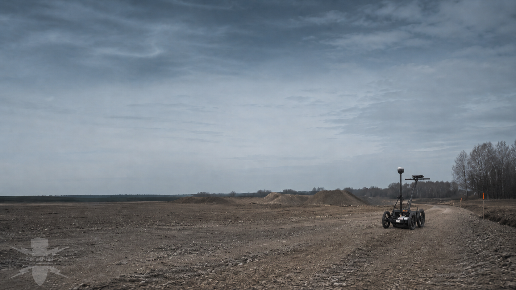
Demolition and replacement of a platform edge affect strip foundations, backfill, supporting layers and adjoining track areas. Investigation geometry follows the edge alignment, construction section and actual planned excavation depth.
Existing edges, reinforcement and installations can affect survey feasibility. Suitable additional investigation is planned for zones exposed later.
Investigate the platform edge and excavation volume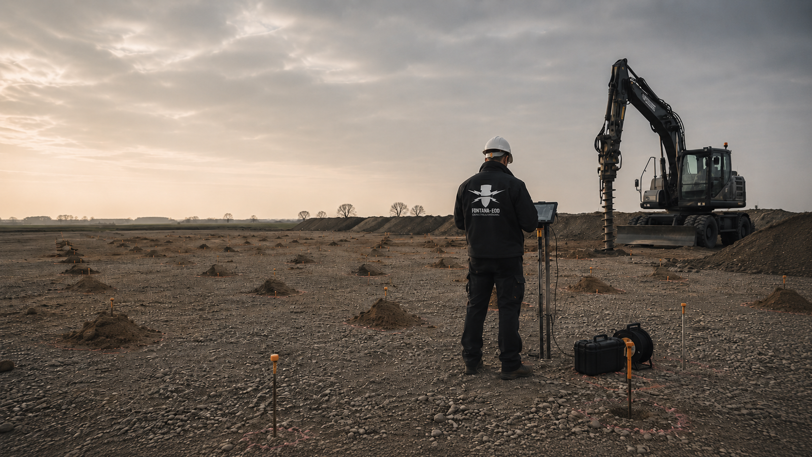
Lift shafts, stair flights and access routes create deep excavations, excavation-support alignments and individual foundations. For these structures, a near-surface area survey is generally insufficient as the sole basis.
Borehole positions, design depths, excavation support, working volume and construction stages are used to assess the additional investigations required and their technical suitability.
Investigate deep excavations and foundationsRamps, access paths and forecourts combine linear earthworks with local retaining walls, drainage and connections to existing structures. Explosive ordnance investigation follows actual ground regrading rather than just the surface visible afterwards.
Subareas outside the platform structure are documented separately where their construction stage or depth of ground disturbance differs.
Assess station and surrounding areasCable ducts, protective pipes, drainage pipes and chambers often run alongside the platform edge or cross access routes and track areas. Existing utilities and new alignments are included in the investigation drawing with their width, depth and construction sequence.
For signalling cables and technically congested corridors, the cable alignment, chamber construction, individual installations and required records are coordinated with the specialist cable and signalling investigation.
Investigate cable and signalling routes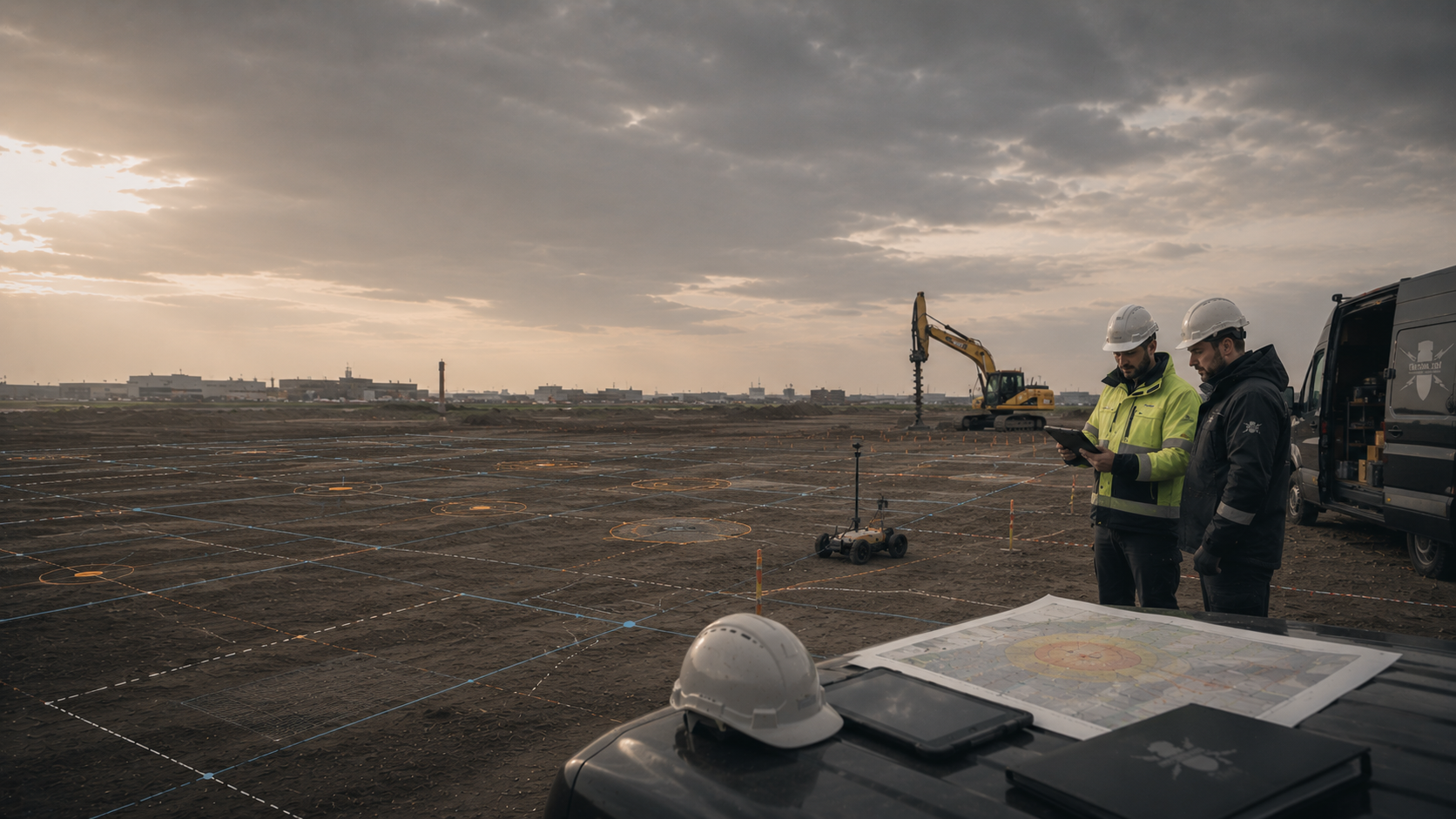
Platform roofs, lighting masts, shelters and displays require individual foundations or anchors. Investigation follows point position, foundation geometry and installation method.
Relocated supports or equipment positions added later are not automatically covered by an earlier area survey.
Choose methods for individual foundationsSurfacing, foundation remains, utilities, reinforcement and operational installations may prevent a complete preliminary investigation. The investigations and protective measures needed are specified before ground disturbance during demolition. Areas accessible afterwards receive the additional investigation required for the further work planned there. Whether explosive ordnance surveying during construction is suitable is assessed for the respective excavation.
Excavation layers, stop points and handovers are agreed with site management before work begins.
Schedule excavation monitoringPlatform projects often change between preliminary design, tendering and construction. New structural positions, revised depths or existing installations identified only during demolition are therefore checked against the documented investigation scope.
At early design stages, the existing platform, new edge, access routes, lifts, ramps and construction stages are compared spatially. The historical evidence of ordnance identifies sections needing further investigation.
For design options, assess whether revised structural positions create additional areas or depth volumes.
Assess the suspected risk for each optionService limits, drawing revisions, subareas, depths, method suitability, alternative measures and documentation requirements must be described so that bids are based on the same scope.
General items without structural and depth references regularly leave room for interpretation during construction.
Define service specifications and investigation recordsIf the working volume becomes accessible only after surfacing, the edge or equipment is removed, investigation is incorporated into the demolition sequence. Accessible subareas can be investigated in advance; remaining zones receive a defined later investigation step.
The handover between demolition, surveying and new construction is documented by section.
Coordinate demolition and excavation monitoringFor shafts and excavation support, the excavation outline, design depth, working volume, support positions and possible boreholes are considered together. An existing platform investigation is used only insofar as its geometry actually covers this volume.
Unresolved depth volumes receive their own technical follow-up measure.
Investigate the shaft and excavation support at depthDifferent utility routes, unknown chambers or new cable alignments affect survey feasibility and the construction sequence. Project documents are updated before additional earthworks begin.
Known installations are considered in the assessment both as sources of interference and as relevant as-built information.
Update the utility and cable corridorA survey anomaly, an object causing technical interference and an actual suspicious object are distinguished technically. If an unexpected suspicious object is encountered, work stops immediately. It is left untouched and is not exposed further. Leave the immediate area and contact the police in Germany; outside Germany, the local emergency reporting procedure applies.
The follow-up decision depends on the findings, working surroundings and regional responsibilities.
Assess the findings and recovery procedureOrdnance evidence, structures, depths, construction stage and survey conditions are reviewed together when selecting the investigation. The areas to investigate and records to provide to site management are then specified.
Initial situation: No reliable spatial ordnance assessment is available for the station or individual platform sections.
Technical step: Historical aerial photographs, maps, previous uses and available information are related to the current drawing revision.
Documentation objective: Defined areas of suspected ordnance and data gaps as a basis for technical investigation.
Establish the historical evidenceInitial situation: Surfacing, supporting layers, backfill or a utility route are to be worked on across an area or strip.
Technical step: A suitable surface method is selected according to the soil, surface, installations and depth required.
Documentation objective: Survey area, interference zones and follow-up decision with clear station references.
Select a suitable area survey methodInitial situation: Shafts, piles, excavation supports, roof supports or masts extend beneath the zone assessed by area surveys.
Technical step: Point coordinates, design depth and future ground-disturbance geometry are incorporated into a depth or borehole investigation.
Documentation objective: Point-specific assessment with clear limits outside the investigated volume.
Plan deep points and foundationsInitial situation: Utilities, reinforcement, foundations or operational installations prevent a reliable preliminary investigation.
Technical step: Subareas that can be surveyed are investigated separately. For the remaining zones, access timing and the investigation method suitable for the planned ground disturbance are assessed.
Documentation objective: A spatially identified limitation rather than a general conclusion for the whole site.
Incorporate remaining zones into the construction sequenceInitial situation: Surveying or excavation reveals a relevant anomaly within the planned working volume.
Technical step: Survey anomalies are assessed using position, depth, data quality and known existing objects. Additional surveying or specialist exposure is then decided upon. For a suspicious object, the immediate safety measures and emergency call apply.
Documentation objective: A clearly documented follow-up decision for the affected section.
Arrange specialist follow-up on the findingsInitial situation: The platform, access route and technical installations are constructed over several possessions and construction stages.
Technical step: Investigated and unresolved areas are brought together for each drawing revision and construction stage.
Documentation objective: A usable status drawing for site management, the client and subsequent trades.
Structure section-specific recordsA usable project file must identify, even after drawing revisions and construction stages, which area, depth and structural geometry were investigated and with what result.
Documentation remains limited to the working volume actually investigated or monitored.
The railway line, station, track, platform, kilometre reference or chainage, drawing revision and construction section provide the common spatial basis. Structures such as lifts, stairs, edges and utilities also receive their own identifiers.
Changes are not merely mentioned in the text but updated on the site drawing and in the investigation status.
Aerial photograph assessments, archive indications, earlier finds, official letters and available statements are documented with their date and spatial scope.
Contradictions or missing appendices remain visible and are not replaced by a general summary.
Survey areas, lines, borehole positions, excavation sections and depths are related to the future working volume. For lifts, excavation support and foundations, the records must identify which part of the excavation or foundation volume was covered.
Zones not reached receive their own identifier and follow-up measure.
Surface, platform structure, soil, utilities, reinforcement, foundations, access, possessions and construction stage are recorded by section.
This information explains the conditions in which the data were obtained and the methodological limits to consider.
Anomalies, objects causing technical interference, exposure work and actual findings are recorded separately. Position, depth, investigation status and next measure remain linked through a common identifier.
Outstanding points are not shown as complete while their project question remains unanswered.
The report links the drawing revision, investigated areas, methods, results, limitations and remaining measures. For multi-stage redevelopment, section reports can be combined with an overall status summary.
After exposure or clearance work has actually been carried out, the findings and clearance records are assigned the same station, structure and depth references. This allows site management to identify the investigation status and any further investigations needed for the next work step.
Platform redevelopment is often delivered through staggered possessions and construction stages. The project file contains the ordnance evidence used, investigation logs, results and outstanding tasks.
Each document has a clear reference to the structure, section, drawing revision and investigation status.
The historical assessment, official correspondence, as-built drawings, ground investigation data, utility documents and earlier investigation reports are recorded with their drawing revision and scope.
Missing information or information only partly applicable is identified as an outstanding project task.
The platform edge, lift, stairs, ramp, roof support, chamber, cable alignment and drainage share common positional references and identifiers.
These references allow later updates without combining different ground disturbances into an undefined overall area.
Raw and interpreted data, survey lines, grids, borehole positions, depths, interference zones and control areas are filed in the agreed data structure.
Automatic displays do not replace specialist plausibility checks against existing installations and project geometry.
Monitored layers, equipment, working times, interruptions, anomalies and deviations are documented continuously for each section.
The spatial origin of the soil investigated remains identifiable even during temporary storage or handover by section.
Each outstanding point has a position, status, assessment, responsibility and planned follow-up measure.
Exposure, additional surveying, construction adjustments or official handling of finds can then be followed transparently.
Reports, drawings, an appendix list and unresolved remaining areas are handed over to the client and site management as a consistent set. After exposure or clearance work has actually been carried out, the corresponding findings and clearance records supplement the project file.
The assessment applies to the documented drawing revision and construction stage; later changes are reassessed for investigation requirements.
The process follows the actual construction sequence. Before each earthworks step, existing records are checked for coverage of the proposed working area.
Complete preparation supports work within short possession windows; technical minimum requirements for surveying, assessment and documentation remain unchanged.
Platforms, access routes, lifts, stairs, ramps, technical equipment, utilities and construction stages are taken from the current drawing revision.
The type of ground disturbance, depth and assessment required are described for each structure.
Historical information, as-built and utility drawings, ground investigation data, earlier reports and requirements are checked for spatial consistency.
Data gaps and contradictory drawing revisions are clarified before fieldwork or documented as outstanding prerequisites.
Platform areas, deep excavations, individual foundations, cable alignments and zones accessible only during demolition are defined separately.
This allows a suitable specialist service to be specified for each working volume.
Survey objective, soil, surface, technical interference, access and depth determine method selection.
Further investigation options are assessed for areas that cannot be adequately surveyed. Explosive ordnance surveying during construction is specified only where technically suitable for the ground disturbance.
Points, areas, chainage, construction sections, possession windows and responsibilities are checked with designers and site management.
Design changes before mobilisation are incorporated into the scope of work.
Area surveys, depth investigations and services during construction follow the defined geometry.
Deviations and inaccessible zones are recorded spatially during construction.
Survey readings, objects causing interference, exposure work and field observations are checked for plausibility against the ordnance evidence and structural geometry.
A technically justified follow-up decision is made for outstanding points.
The report, status drawing, data, limitations and next measures are prepared for site management and subsequent trades.
New construction stages or drawing revisions are checked against the existing investigation scope.
Explosive ordnance investigation follows the actual construction and working volumes below the surface rather than the station visible afterwards.
Structural identifiers, chainage, coordinates, depths and construction stages together form the basis for surveying, excavation monitoring and records.
At a platform, area demolition zones, linear edge foundations, individual supports and deeper excavations may coincide. The investigation strategy must match the actual working volumes and depths of ground disturbance planned.
Especially for lifts and subways, the visible shaft area is insufficient as an investigation boundary. Excavation support, working volume, slopes, borehole positions and temporary access can extend the ground disturbance relevant to ordnance.
Design therefore brings together planned and as-built positions, drawing revisions and depths actually reached. Zones not covered remain visible in the report and are assigned a specific follow-up measure.
For redevelopment by section, each handover status is tied to the documented construction stage. Deeper work later or a relocated utility alignment triggers a fresh technical assessment.
The edge foundation, demolition zone and adjoining platform structure are described as a connected but depth-dependent corridor.
Crossings, chambers and locally deeper excavations are also identified because they create different investigation geometry.
The excavation outline, support alignment, borehole positions and design depth are recorded on a common drawing.
Relocation of the shaft or a change in excavation support type can create new depth volumes not previously covered.
Investigation follows ground regrading, retaining walls, foundations and utility crossings.
Near-surface paths and deep support or foundation points are not covered by the same assessment.
Alignment, width, depth, chambers and crossings determine the spatial investigation requirements.
Existing utilities and new routes are recorded together so that survey interference is not confused with actual construction geometry.
Areas accessible in advance, zones reached after surfacing is removed and areas opened only after structural demolition have their own status information.
A subarea can then be handed over without losing sight of unresolved adjoining areas.
If the platform edge, lift, support layout or utility route changes, the new working volume is checked against the documented survey and point geometry.
Only areas actually covered can be carried over from the existing records.
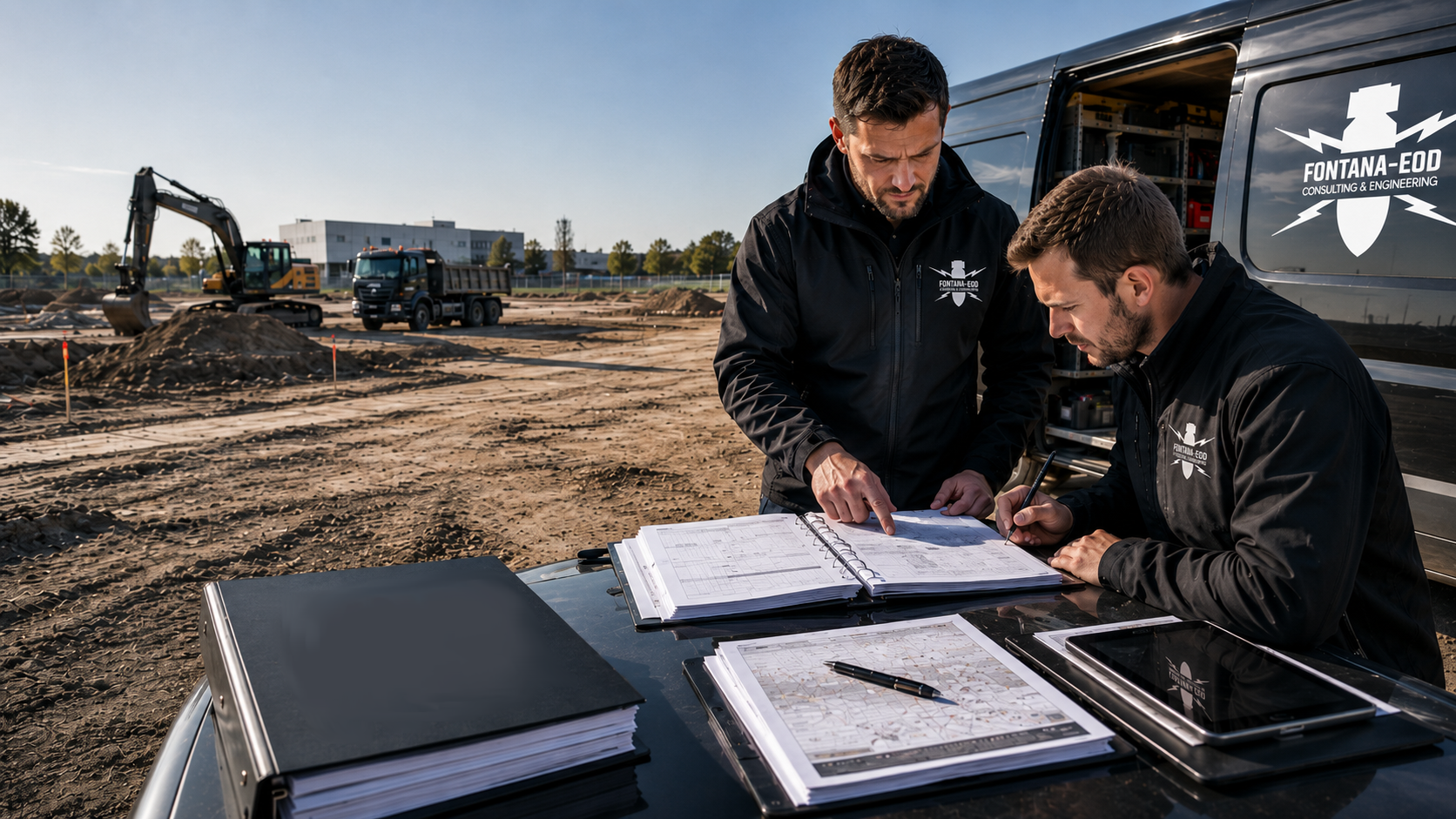
For demolition, new platform edges, lifts, stairs, ramps, cables, drainage and technical equipment, the available ordnance assessment and investigation documents are first reviewed. This establishes the further investigation needed for the affected volumes of ground.
Identify applicable existing investigation documentsInvestigation requirements depend on the specific structure, its depth, the current construction stage and which areas can be surveyed in advance or become accessible only during demolition.
Choose methods by structure and accessThe methods respond to different physical properties and have their own area and depth ranges.
Combining methods is useful only where each answers a clearly defined part of the station redevelopment question.
Assesses whether historical evidence indicates possible ordnance and which station areas are affected.
It does not detect objects present today and does not replace technical investigation of the structural volume.
Responds to ferromagnetic objects and can be used on suitable open areas.
Rails, reinforcement, utilities and metal equipment can substantially limit the assessment within a station.
Records time-dependent electromagnetic responses from conductive objects.
Suitability depends on the target object, depth, ground conditions and electromagnetic surroundings and is assessed by section.
Shows reflections at material and structural boundaries and can provide additional information on suitable paved surfaces.
A reflection does not automatically identify an object; ground conditions and knowledge of existing installations determine interpretation.
Investigates defined point and depth volumes for lifts, piles, supports, excavation support and other deep ground disturbance.
The conclusions apply only to the defined investigation geometry.
In suitable excavation areas, each working layer is surveyed and assessed by a specialist. Controlled excavation in layers and an additional visual inspection follow. These steps are repeated to the agreed base of excavation; simply watching the excavator is insufficient.
It requires defined excavation layers, stop points and section-specific documentation.
The quality of an explosive ordnance investigation is demonstrated by the structure, working volume, survey conditions and records all describing the same geometry.
FONTANA-EOD documents the investigations carried out and checks new construction stages against the previous investigation scope. Areas still unresolved are identified in the report.
At the outset, the project decision required is clarified: assessment of design options, tendering, authorisation of the next earthworks step or records for a section already investigated.
The method is not selected according to availability. Soil, platform structure, existing utilities, reinforcement, foundation depth and actual access determine which conclusions can be reached.
During construction, deviations, revised construction stages and newly accessible areas are recorded immediately. Assessment therefore remains aligned with actual site conditions.
When anomalies occur, survey anomalies, objects causing technical interference and actual finds are communicated separately. The next measure follows from data quality, position, depth and regional responsibilities.
The handover to designers and site management describes not just results but also spatial limits and requirements for construction sections still unresolved.
The platform edge, shaft, support, utility and demolition area are described separately before work begins.
Soil, surface, utilities, reinforcement, existing installations and access are included in the suitability assessment.
Changes in position, depth and construction sequence are checked against the previous investigation scope.
Automatic displays are checked against existing installations, geometry and observations at the construction stage.
Inaccessible zones, those affected by interference and areas not yet investigated receive a clear status.
Reports and status drawings answer the specific question for the next construction or design step.
The suitability of area surveys, deep point investigation or explosive ordnance surveying during construction is assessed for the respective structure. A general assessment for the station site does not replace this assignment.
The final documentation must identify which platform section, depth and drawing revision were investigated and which follow-up measures remain for unresolved zones.
Station projects bring together clients, operators, designers, site management, specialist contractors and public authorities. Before work begins, responsibility for reporting changes, commissioning investigations and passing records to site management is specified.
Each role receives the information needed for its own decision; technical assessment, operational authorisation and official action remain distinguishable.
Define project objectives, construction stages, drawing revision, the assessment required and programme priorities. They provide existing documents and commission the specialist services needed.
Across several work packages or construction sections, they maintain a consistent data and handover structure.
Translates station redevelopment into structures, excavations, foundations, utilities, depths and drawing revisions. It incorporates explosive ordnance investigation into design, bills of quantities and construction-stage planning.
Revised structural positions are passed to the specialist participants before construction.
Set requirements for access, possessions, protection zones and operating conditions around the station and tracks.
Operational authorisation of a working window and the technical conclusion of the explosive ordnance investigation serve different purposes.
Carry out demolition, excavation in layers, drilling, excavation support and foundations in accordance with the agreed drawing revision. Deviations are reported before the affected ground disturbance.
If an unexpected suspicious object is encountered, they stop work immediately, leave it untouched and leave the immediate area. In Germany, they contact the police without delay; outside Germany, the local emergency reporting procedure applies.
Reviews the ordnance evidence and design information, develops the commissioned approach, carries out the specialist service and documents results and the limits of the assessment.
The service remains related to the agreed structure, area and depth volume.
In Germany, the ordnance disposal services of the federal states and the locally competent authorities carry out hazard-response and find-management duties. Their involvement is established for the project location; outside Germany, local responsibilities apply.
An actual find is reported through the procedure agreed in advance.
The local public order authority and, where applicable, building control are involved according to regional procedures and the construction task. Contacts and requirements are assigned to the station section and applicable drawing revision. Technical investigation status, operational work authorisation and official decisions about finds remain separately documented.
Guidance overview and terminology Assess regional procedures for findsRequirements depend on the activity, project location, construction stage and operating environment. The service specification, qualifications, risk assessment and documentation must therefore relate to the specific commission.
Operator and site rules supplement the technical framework but do not replace a clear definition of the explosive ordnance service scope.
In Germany, § 7 SprengG concerns the commercial authorisation for activities requiring authorisation; § 20 SprengG concerns the certificate of competence of responsible persons. Under § 1b SprengG, searching for found munitions also counts as handling them. The requirements applicable to the project depend on the activity actually commissioned.
DGUV Information 201-027 supports risk assessment and protective measures for ordnance clearance work. The Baufachliche Richtlinien Kampfmittelräumung set requirements for investigation, clearance concepts, quality and documentation within their defined scope of federal responsibilities. Their application to the specific station project is clarified separately.
Platform work also involves operational safety, access and construction-sequence requirements. These are coordinated with surveying, demolition and earthworks without conflating the respective responsibilities.
If a suspicious object is found, stop work in the affected area immediately. Do not touch or move the object, leave the danger area and keep others away without putting yourself at risk. In Germany, notify the police immediately on 110; outside Germany, use the local emergency reporting procedure. Then inform site management.
The First Ordinance to the German Explosives Act (1. SprengV) includes requirements for specialist competence and state-recognised training courses. Qualifications and actual scope of work are defined together for investigations of individual station structures.
DGUV Rule 113-003 concerns the dismantling or destruction of explosives or corresponding objects and also includes the disposal of found munitions. It applies according to this field of activity; it does not replace a risk assessment specific to the planned ground intervention.
The permit requirements, responsible person and actual commissioned task are matched to the specific work scope before construction.
Operations, traffic, electrical installations, demolition, earthworks, protection zones, escape routes and communication are considered together for the project.
Structures, areas, depths, methods, alternative measures, quality control and required records are clearly specified before procurement.
Site management, project leads, railway safety personnel and competent authorities follow an agreed procedure for anomalies and finds.
The drawing revision, construction sections, access, qualification requirements, data formats and acceptance criteria are defined so that bids are technically comparable.
Contingent items have a clear trigger and a defined documentation requirement.
Working areas, briefings, railway safety arrangements, surveying, equipment, contacts and stop points are checked against the applicable operating and construction stage.
Last-minute changes are incorporated into the scope of work.
Work stops immediately. Do not touch or move the object, leave the danger area and keep others away without putting yourself at risk. In Germany, notify the police immediately on 110; outside Germany, use the local emergency reporting procedure.
Further action follows the instructions of the competent authority.
The site drawing, structural references, survey data, point lists and section status must describe the same drawing revision and working volume. This is essential for site management, specialist designers and contractors to retain a reliable data basis when changes occur later.
For redevelopment by section, the document defining the approved drawing revision for surveying, civil works, lift construction, the platform edge and technical equipment is also specified. Contract variations, relocated foundations and newly accessible areas can then be checked specifically against the existing investigation status.
The drawing links structural identifiers, working volumes, depths and investigation status. It remains clear which areas have already been investigated and which become accessible only at a later construction stage.
Have the station drawing technically reviewed
The available evidence and areas with suspected ordnance determine which subareas need more detailed technical investigation. Data gaps remain visible as a separate project task.
Clarify the evidence of ordnance for the stationDeep excavations and foundations receive their own investigation records. A platform area survey is used only insofar as it covers the actual depth volume.
Investigate lifts and foundations at depthExcavation layers, stop points and investigated areas are recorded continuously. The conclusions remain limited to the volume of ground actually monitored.
Plan demolition and excavation monitoring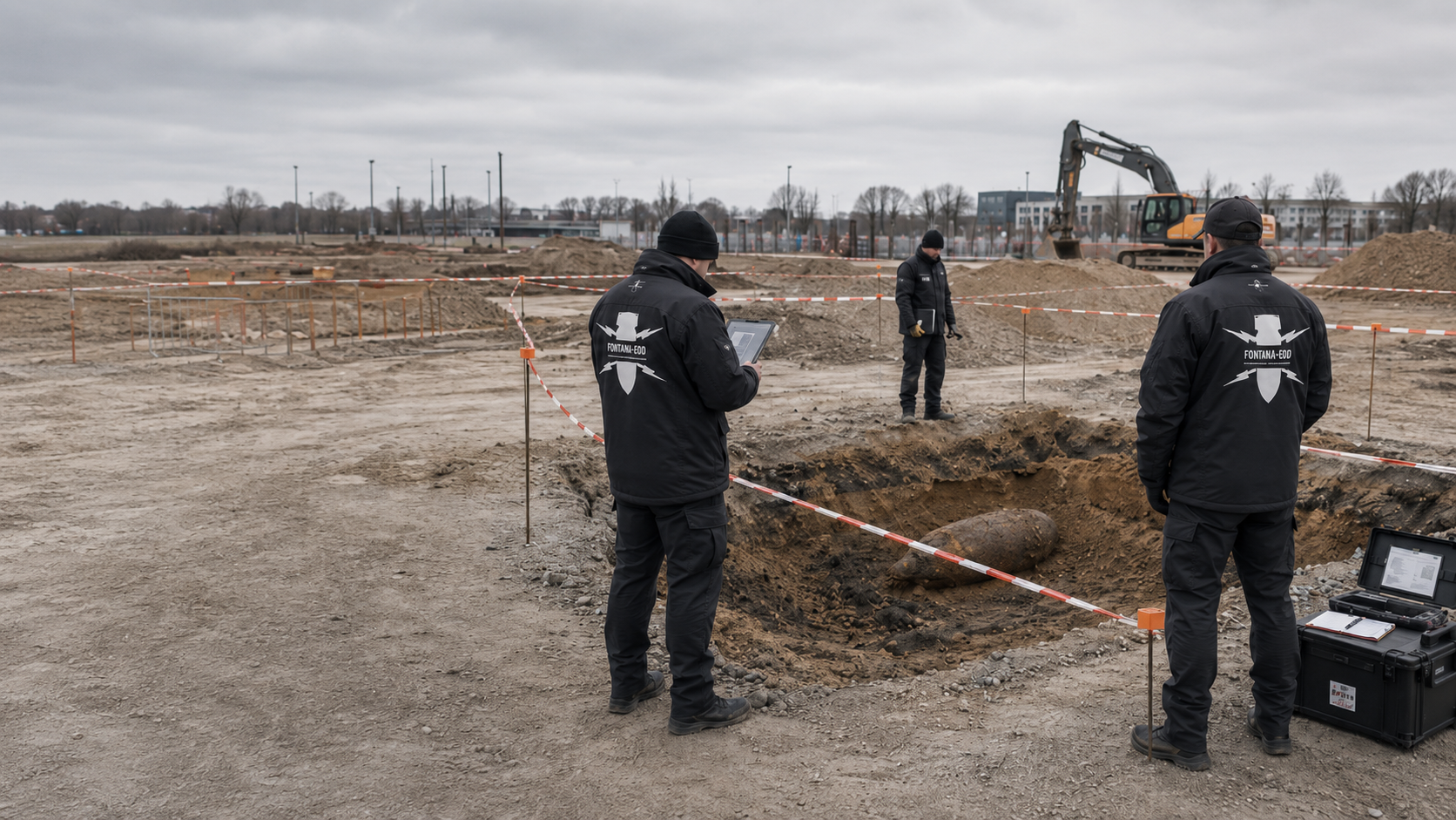
The original station or point reference is retained through to further investigation or action. Responsibilities and handovers are documented so that they remain traceable.
Assess the findings and recovery procedureThe documentation supports tendering, site management and later drawing revisions. It describes the status reached without extending conclusions to sections not investigated.
Structure the project file and handovers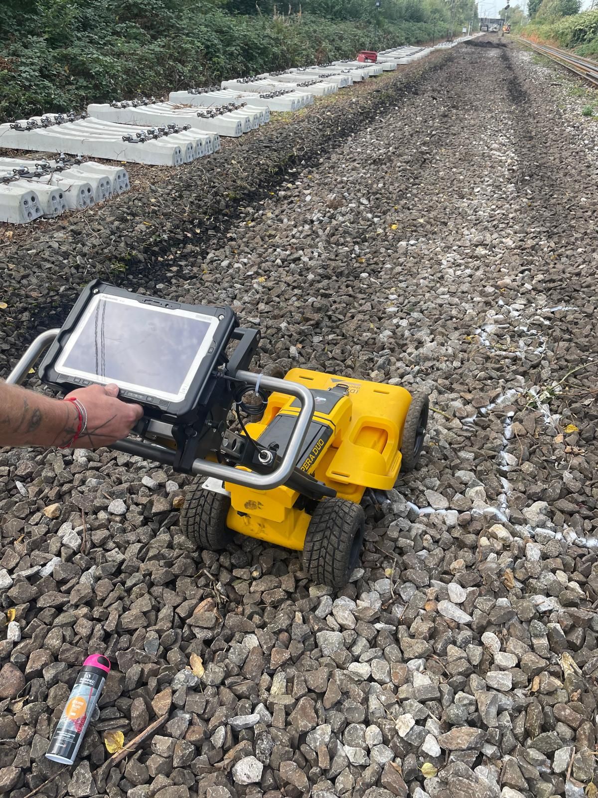
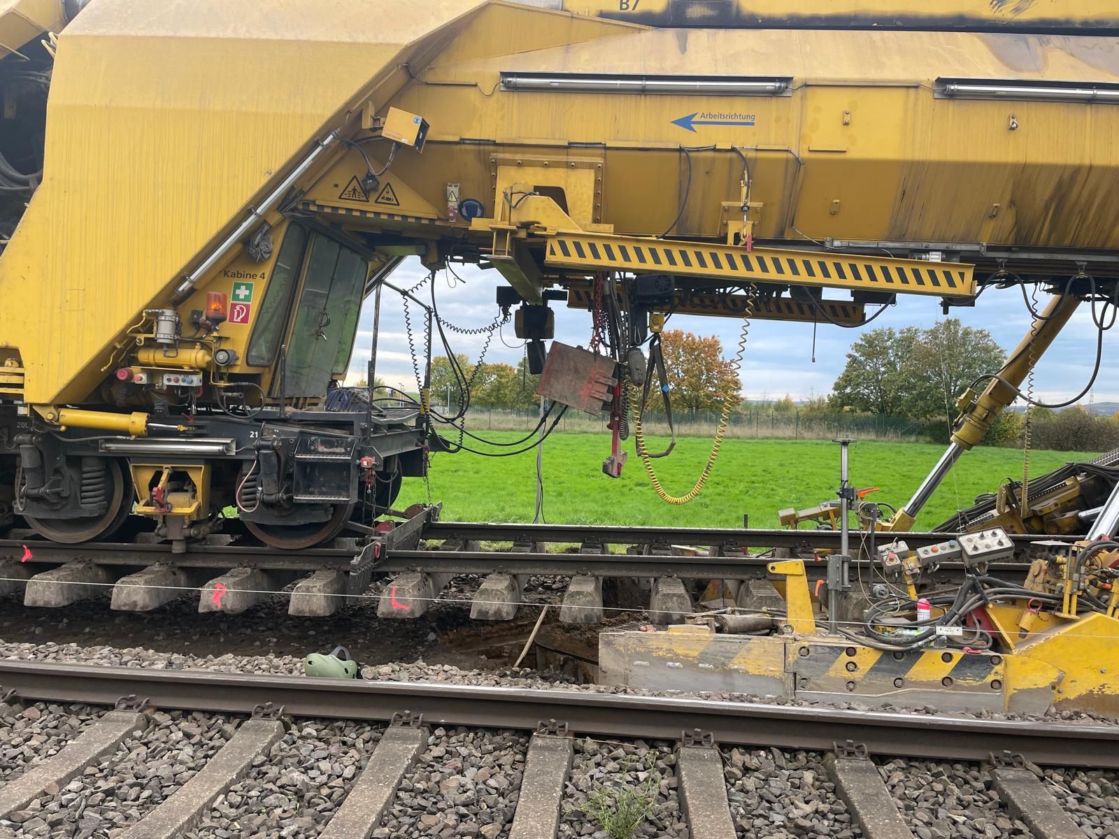
Coordinate track construction, cable civil works and civil engineering structures with their respective working volumes and construction stages.
Assess the railway project in its overall contextClarify the spatial scope of historical indications and data gaps before comparing design options, tendering or technical surveying.
Assess the historical evidence of ordnanceRelate deep shafts, piles, supports and borehole positions to the future ground-disturbance geometry.
Investigate deep excavations and points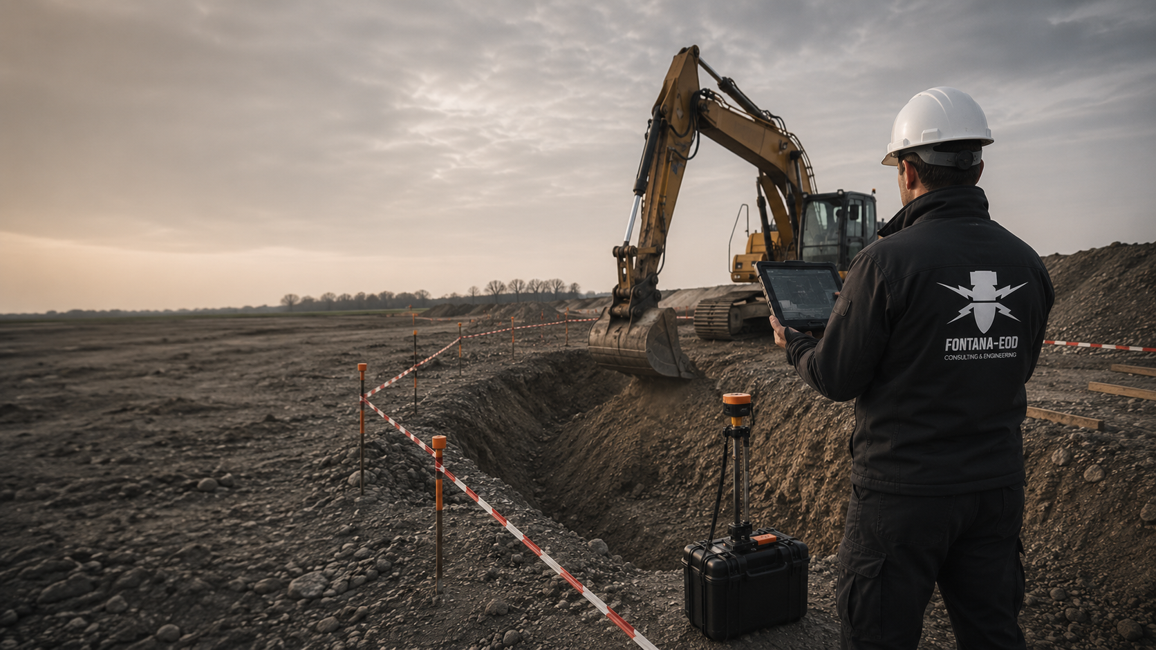
Assess whether explosive ordnance surveying during construction is technically suitable for the remaining excavation areas.
Prepare the technical scope of excavation monitoringCoordinate service specifications, data structure, status drawings, section reports and handovers across several construction stages.
Define procurement and investigation records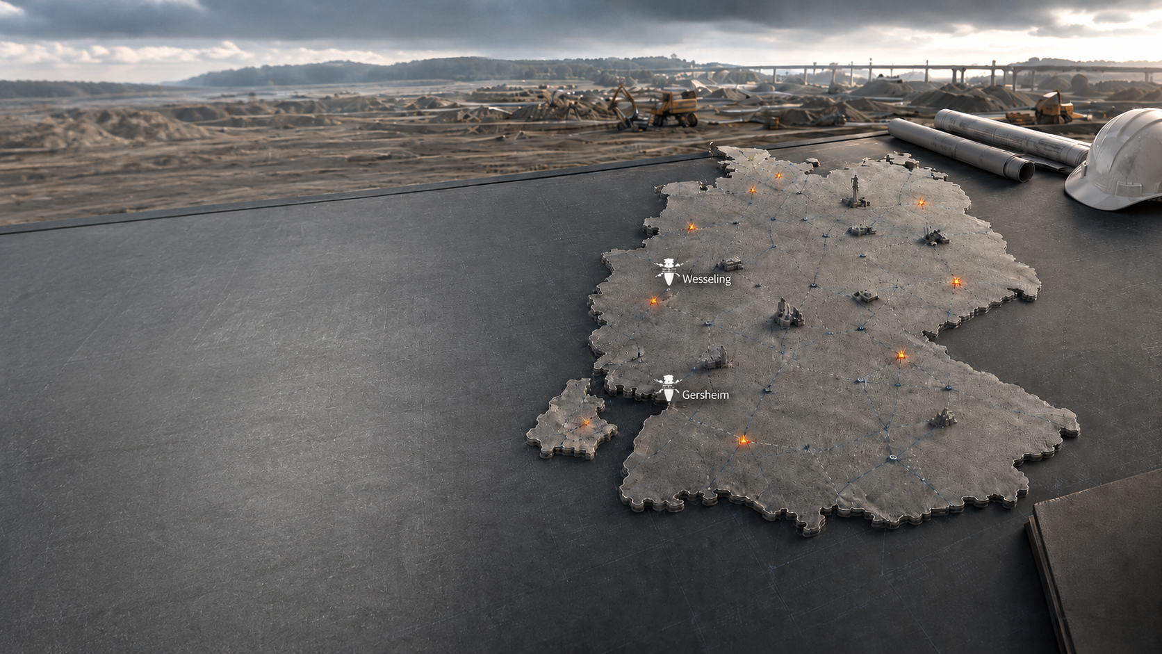
Identify the project location, federal state and local interfaces for coordination and possible finds.
Clarify regional responsibilitiesDefine the technical scope of the wider station area, including railway yards, operational areas, workshops and ancillary installations.
Assess station and operational areasInvestigate cable alignments, chambers, crossings and signal foundations as separate linear and point working volumes.
Investigate cable and signalling worksProvide the station, track, platform side and applicable structural drawing. Also mark lifts, access structures and utility sections outside the platform. This relates the investigation brief to the actual working volume rather than inferring the investigated area from a general station name.
An investigation at the platform edge does not automatically describe the ground beneath a lift shaft or roof foundation. Compare structural identifiers, drawing revision and depth references before using an existing report for another construction section.
Check section-specific recordsOperational access and possession windows determine how work is organised. Whether the available investigation window is technically sufficient also needs assessment against survey conditions and the working volume. An available date does not demonstrate that investigation is feasible.
Assess the basis for investigationTechnical information
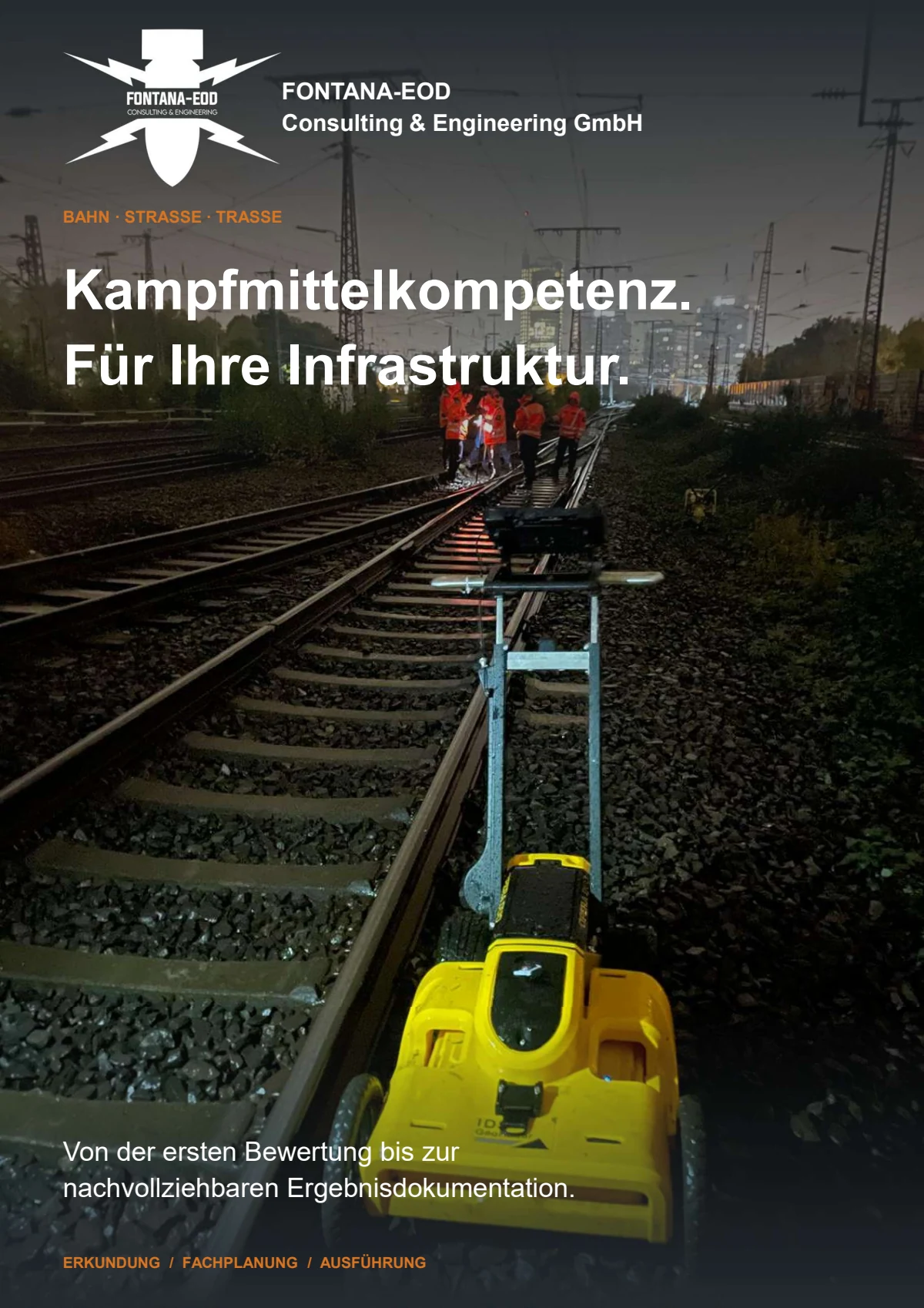
The brochure shows how FONTANA-EOD combines historical investigation, specialist planning, surveying and construction supervision in infrastructure projects. It explains trackside constraints, method selection and limitations, and result documentation.
Technical assessment should take place as soon as demolition boundaries, new platform edges, access routes, lifts, utilities and foundation points are sufficiently defined. Early design can begin with assessment of the historical evidence of ordnance. Before tendering and construction, the actual areas, depths and construction stages must be addressed through suitable technical investigation or a planned follow-up measure.
Platform structures, edge foundations, lift shafts, stairs, ramps, subways, roof supports, lighting masts, cable routes, drainage, chambers and temporary excavations disturb the ground in different ways. Each area is assessed by position, depth, working volume and construction method. A general area assessment for the whole station does not replace this assignment to individual structures.
This depends on the surface, platform structure, utilities, installations, reinforcement, technical equipment and access. Some subareas may be surveyable in advance; others become accessible only after surfacing, equipment or structural elements are removed. For zones accessible later or affected by strong technical interference, suitable additional investigation and its timing are assessed during design.
Lift shafts, stairs and ramps involve deep excavations, foundations and excavation support. Their investigation geometry must cover the entire future working volume, including temporary slopes, support alignments and borehole positions. Near-surface surveys can provide initial information but do not automatically replace depth investigation of the actual foundation or excavation.
Cable protection ducts, cable channels, drainage pipes, chambers, lighting, shelters, displays and other equipment are included in the investigation drawing with their position, depth and construction sequence. Known installations help interpret survey data but may also limit individual methods. Unclear or revised utility routes are reassessed before the respective ground disturbance.
Clear drawing and station references, investigated areas and depths, methods used, survey or field conditions, findings, technical limitations, inaccessible areas and the respective follow-up decision are required. For redevelopment by section, drawing revisions and handovers are updated so that later construction stages do not rely on a broader assessment than was actually documented.
Official information and requirements are included with complete appendices, dates and spatial scope. In Germany, the relevant ordnance disposal service, local public order authority and, where applicable, building control are identified for the project location; operational work authorisations remain separate processes. Outside Germany, coordination is with the authorities responsible locally.
Explosive ordnance surveying during construction is considered where technically suitable for the planned ground disturbance. This may concern areas accessible only during demolition or not adequately investigated in advance because of utilities, reinforcement or foundations. Each working layer is surveyed and assessed by a specialist. Controlled excavation in layers and an additional visual inspection follow; these steps are repeated to the agreed base of excavation. Excavation layers, equipment use, stop points, responsibilities and reporting procedures are defined before work begins. The conclusions remain limited to the working volume actually investigated.
If an unexpected suspicious object is found, stop work. Do not touch, move or uncover it further. Leave the immediate area and warn others without putting yourself at risk. In Germany, notify the police on 110; outside Germany, use the local emergency reporting procedure. The competent authorities determine what happens next; a project enquiry does not replace reporting the find.
Key factors are the number and length of platforms, demolition and new-construction sections, access, possessions, surface structure, existing utilities, number of deep foundations, methods required, construction stages and documentation scope. A reliable estimate therefore needs current drawings, clear depths of ground disturbance and an identifiable sequence of construction stages.
An initial enquiry does not need to contain a complete bill of quantities. The essential requirement is a clear spatial description of the affected structures, types of ground disturbance and construction stages.
Where there are several platforms or redevelopment stages, provide priorities and the dates when decisions are needed.
Provide the station, railway line, track, platform, kilometre reference or chainage, current drawing revision and planned construction sections.
Lifts, stairs, ramps, edges, roofs, utilities and chambers should be identifiable with clear references and dimensions.
Describe demolition, excavation, excavation support, boreholes, piles, foundations, utility trenches and maximum depths.
Possessions, access, construction stages and the date when a decision is needed affect the method and site planning.
Include aerial photograph assessments, official correspondence, previous reports, ground investigation data, utility and as-built drawings, and earlier survey or clearance documents.
Incomplete or contradictory documents also help identify the questions still needing clarification.
For an initial comparison, a site drawing, current design, short description of demolition and new construction, maximum depths, planned dates and existing ordnance evidence are often sufficient.
FONTANA-EOD uses these documents to assess the investigations needed and identify missing information. For complex stations, work can be divided by structure, possession phase and handover date.
Station, platform, track, chainage, construction section and drawing revision.
Edge, lift, stairs, ramp, support, utility, chamber and maximum depth of ground disturbance.
Demolition sequence, possessions, access, parallel trades and handover dates.
Documents for design, procurement, site management, operator communication or the project file.
Whether historical aerial photograph analysis, explosive ordnance surveying, surface surveying using GPR, magnetometry or TDEM, deep-ground surveys, downhole surveys, excavation supervision, area clearance or ordnance recovery is needed depends on the location, ground disturbance, depth, ground and existing documents. An early ordnance assessment provides clarity for tendering, programming, occupational safety and construction.
FONTANA-EOD combines its Section 7 SprengG licence, specialists holding Section 20 SprengG certificates of competence, suitable survey and clearance methods, and traceable documentation. Send the site plan, depth of ground disturbance, construction phase and existing documents for an initial technical assessment.


