Project pathway
The quickest route to the right decision.
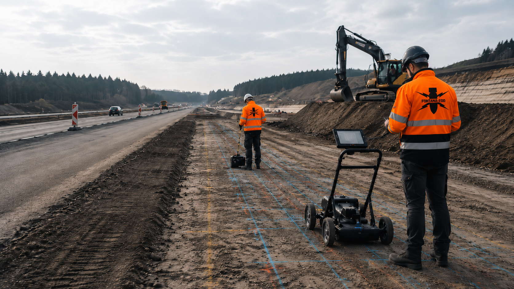
For retaining walls and other civil engineering structures, we consider excavations, foundations, shoring and anchors together with the planned groundworks. FONTANA-EOD plans suitable investigations according to structural geometry, intervention depth and access during individual construction phases. Send structural drawings, sections, element schedules and the construction sequence so that the required services and documentation can be established before foundation, shoring and excavation work.
Distinguish foundations, piles and shoring.
Locate the excavation base, anchors and boreholes.
Document each construction stage.
Before a retaining wall or civil engineering structure is built, the explosive ordnance investigations needed for foundations, piles, shoring, anchors and excavations are established. Existing indications of suspected ordnance are compared with structural geometry, depth and installation methods. Temporary shoring and other temporary ground interventions also form part of planning. Technical survey limitations and subsequent access are documented so that the investigation remains aligned with the actual volume of ground affected and the relevant construction phase.
The scope of services for “Radevormwald (Dahlhausen) – replacement retaining wall L 414 – SW-A 26-003, BW 4709531 Radevormwald (Dahlhausen) / Germany · Cologne administrative district” comprised downhole magnetometry.
Service period: 2025-01
Service areas:Downhole magnetometry / deep-ground survey
View project details · Deep-ground and downhole surveys · Region: Cologne administrative district
The scope of services for “Kunnersdorf/Bernstadt a.d.Eigen: S128–Herrnhuter Straße – K8613 Kunnersdorf – road construction and retaining wall 1 Kunnersdorf/Bernstadt a.d.Eigen: S128–Herrnhuter Straße / Germany” comprised ground-penetrating radar.
Service period: 2024-12
Service areas:Surface surveys: GPR, TDEM and magnetometryMethod used in this project: Ground-penetrating radar
The scope of services for “Nauders – B185, hairpin widening on Martinsbrucker Straße with hillside bridges and retaining walls Nauders / Austria” comprised ground-penetrating radar.
Service period: 2023-05
Service areas:Surface surveys: GPR, TDEM and magnetometryMethod used in this project: Ground-penetrating radar
Retaining walls and civil engineering structures comprise elements involving different ground interventions. Reliable planning distinguishes excavations over an area, deep foundations, linear shoring, anchors and associated utility or drainage works.
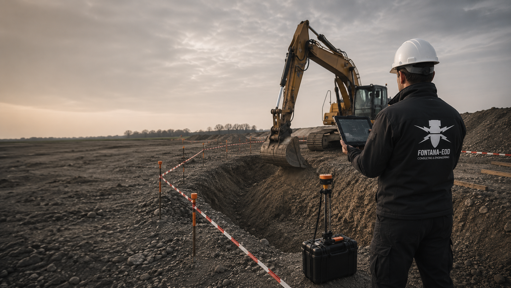
The foundation base, foundation width, frost skirts, backfill and working space determine the near-surface investigation area.
Accessible areas can be surveyed in advance. For edge zones that have not been adequately investigated, the suitability of supplementary measurements or explosive ordnance detection during construction is assessed.
Foundation steps, shear keys and drainage details are taken into account if they lie below the regular excavation base or create additional excavation depth.
Prepare foundation excavation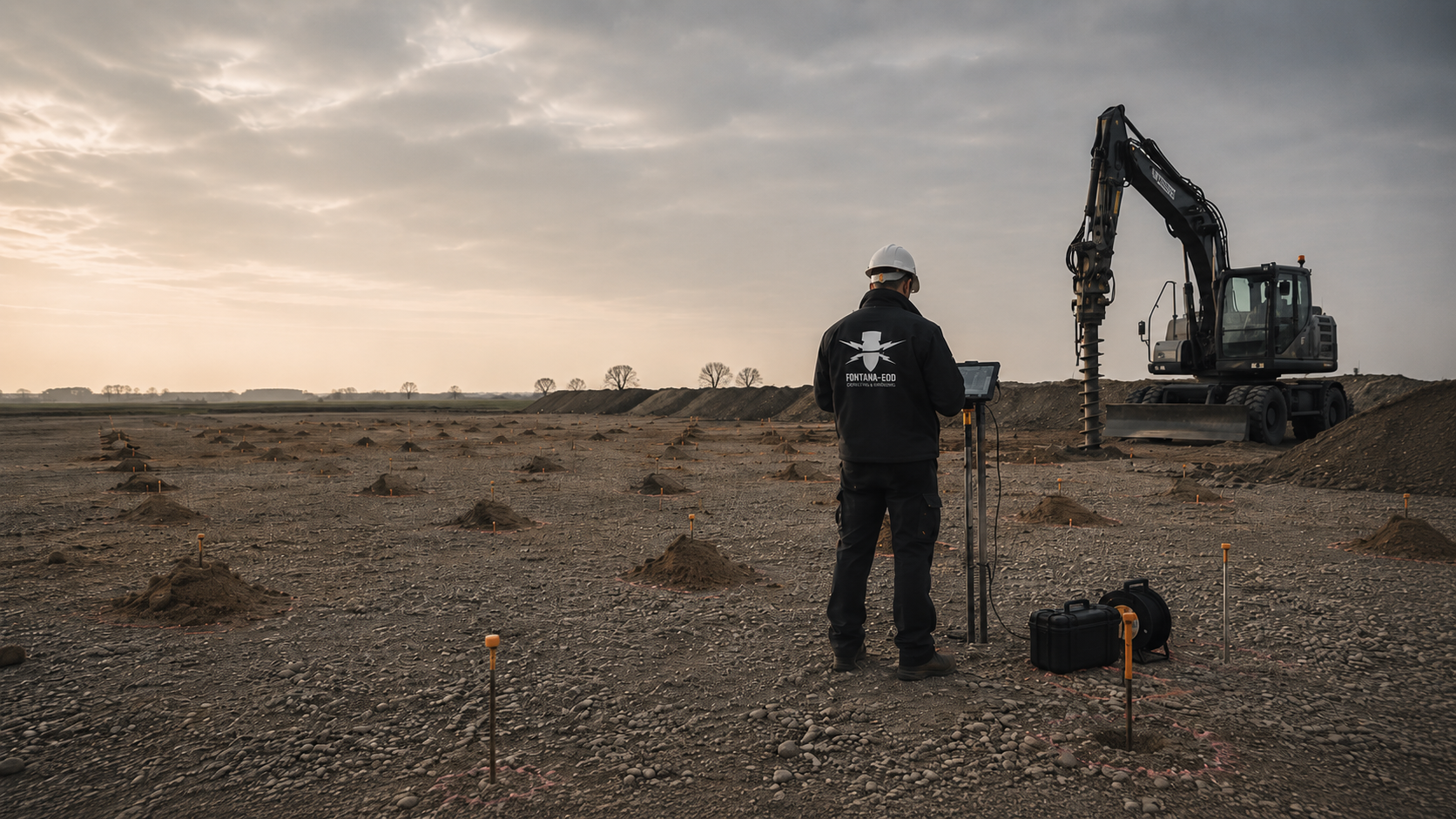
Pile diameter, centre-to-centre spacing, target depth, overlap and installation method define the deep investigation and safety zone.
Each pile receives a unique identifier so that investigation data, evaluation and subsequent installation remain linked to the same point. Whether an additional deep investigation is needed and which method is suitable depend on the actual survey coverage and planned ground intervention.
For pile walls, it is also checked whether primary and secondary piles have different installation sequences or depths.
Assess pile axes and depthLinear shoring alignments extend many metres into the ground and can be installed by impact driving, vibratory driving or drilling.
Alignment, embedment depth, section geometry and any pre-drilling are considered together; a single point measurement is not sufficient for the entire line.
Pre-drilling, replacement drilling and temporary guide structures are treated as separate interventions where they additionally affect the ground.
Plan shoring alignments with specialist input
Anchor lines run at an angle and may extend beyond the visible excavation into uninvestigated areas.
The entry point, inclination, length, bore diameter and target zone must be included in the investigation geometry. Changes to anchor positions are recorded separately.
Their spatial course is checked against property and excavation boundaries on the drawing, because anchors often end beyond the visible wall structure.
Submit anchor geometry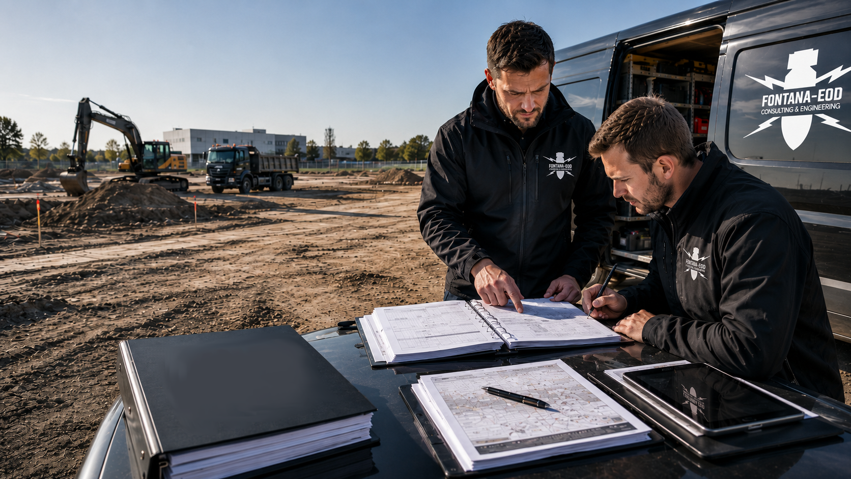
Demolition of structures, existing foundations, dewatering, utilities and changing ground levels create several working stages.
Open areas in front of the structure, deep foundation points and zones accessible only after demolition are treated separately in method selection and coordinated in the construction phasing plan.
Demolition and new-build drawings are maintained separately so that existing foundations are not incorrectly adopted as new foundation geometry.
Coordinate construction phases and recordsDrains, collector pipes, chambers, cables, safety barriers and traffic areas extend the explosive ordnance investigation area beyond the main structure.
The location, depth and investigation required for these ancillary works are also recorded on the drawing.
Ancillary installations are scheduled in coordination with the main structure but may form a separate survey and documentation section.
Assess interfaces with civil engineering worksInvestigation requirements change as planning progresses. Preliminary planning focuses on the corridor of suspected ordnance; before specialist foundation work, structural elements, points, axes and depths must be unambiguously defined.
The structure location, wall alignment, excavation width and possible foundation options are compared on the drawing with historically identified areas of suspected ordnance.
The result identifies sections requiring further investigation and provides a basis for programme and cost assumptions.
During options appraisal, the differences between shallow foundations, piled foundations and anchored shoring are already identified from an explosive ordnance perspective.
Assess the structural corridor using historical recordsThe foundation base, pile or shoring concept, anchor zones and access roads are defined more precisely in spatial terms.
The explosive ordnance investigation is described so that it can be incorporated into the construction sequence, space requirements and protective arrangements.
The planning documents also identify site establishment and assembly areas where heavy equipment will be positioned or ground improvement carried out.
Define investigation areasDrilling, pile, anchor and shoring drawings are checked for point identifiers, depths, inclinations and auxiliary measures.
The volume investigated follows the actual installation process, rather than just the structural element's design axis.
For each group of structural elements, it is specified whether area-, point-, alignment- or construction-phase-specific documentation is required.
Relate deep investigation to the installation processQuantities, surveying, casing, survey paths, data formats and quality checks are clearly specified.
Changed installation methods or alternative tenders trigger an assessment of whether the proposed explosive ordnance measure remains appropriate.
Alternative tenders are assessed not only structurally but also in terms of new drilling axes, installation depths and access conditions.
Refine tender documents with specialist inputDemolition or exposure may make new zones accessible that could not be reliably investigated while existing structures remained in place.
For these construction stages, the suitability of supplementary measurements and the possible use of explosive ordnance detection during construction are assessed.
The demolition plan describes which existing elements must be removed before supplementary investigation and which will remain as interference sources. Necessary investigations and protective measures are planned before ground disturbance during breaking out, demolition or creating access.
Coordinate demolition and excavationAdditional anchors, relocated piles, greater embedment depth or altered excavation geometry are checked against the documented investigation area.
Only structural elements covered by the existing documentation can proceed on that basis.
A design change is incorporated into the construction sequence only once its effect on the survey and documented depth range has been established.
Prepare documentation for changesMethod selection takes account of indications of suspected ordnance, element geometry, intervention depth and achievable data quality. Not every anomaly requires the same measure, and not every unobstructed area provides coverage of deep structural elements.
Aerial photographs, maps, previous land uses and existing opinions are related to the structure alignment, excavation and ancillary areas.
The report delineates areas of suspected ordnance and describes the technical investigations that follow for the planned structural elements.
The historical corridor considered also includes working and storage areas where their construction or use entails relevant ground interventions.
Accessible areas in front of the structure can be investigated across their extent if the ground and interference conditions permit the selected method.
Existing structures, utilities and reinforcement are shown at their own locations as technical limitations.
Survey coverage and interference from existing structures are identified separately so that a zone affected by technical interference does not appear to be an area without anomalies.
For bored piles, micropiles and individual foundations, it is checked whether the required location and depth have been adequately investigated and which supplementary method may be needed.
Survey geometry is derived from the diameter, target depth, installation path and required safety zone.
For pile groups, it is checked whether investigation zones overlap or whether unrecorded zones remain between individual points.
A sheet-pile, soldier-pile or piled wall is planned as a continuous corridor.
Point spacing and survey paths must cover the entire installation line; gaps between individual points are not assumed to be covered.
Particular attention is paid to the ends, corners and transitions of shoring alignments, as sections, depths or installation methods may change there.
Existing foundations, traffic, water or technical installations can limit investigation in advance.
For zones that have not been adequately investigated, possible access stages, suitable methods and hold points are established in advance.
The supplementary investigation is linked to the actual demolition stage, giving site management a clear release point in the sequence.
Technical anomalies are checked for plausibility against existing records and neighbouring measurements.
A specialist decision is made on whether survey anomalies require further investigation or exposure. If an unexpected suspicious object is encountered, work is stopped immediately and the responsible authorities are notified without delay.
The finding decision documents not only the location but also the affected structure and construction phase.
The documentation must link structural geometry, drawing revision, area investigated and result. Only then can structural designers, specialist foundation contractors and site management work from the same status.
The site plan, sections, structure number, axes, element identifiers and current revision form the spatial basis.
Temporary construction stages and auxiliary structures are included where they entail their own ground interventions.
Drawing registers and drawings carry the same revision identifier so that a result is not inadvertently related to an earlier element geometry.
Coordinates, inclinations, lengths, diameters, embedment depths and installation methods are recorded for each element.
Unique identifiers keep changes linked to survey and construction data.
For inclined elements, orientation and the spatial endpoint are also documented.
Historical assessment, known finds, utility data, ground investigation records and earlier structural documents are documented with source references.
Uncertain locations of existing structures or utilities are not treated as established survey conditions.
Existing information is distinguished as surveyed, taken from drawings or merely presumed.
The grid, borehole geometry, survey paths, surface, groundwater, accessibility and interference sources are described for each structural element.
This allows the significance of the results to be assessed by specialists even after later design revisions.
Drillability, water level and casing condition are recorded where they affect survey range or quality.
Anomalies, known installations, zones that could not be investigated and points investigated are recorded on a consistent site plan.
Each unresolved zone is assigned a status, responsibility and further measure.
An unresolved item remains linked to the affected construction work so that its resolution can be checked before the relevant ground intervention.
The report states the stage reached for each structural element and construction stage.
It does not automatically apply to altered axes, additional depths or areas outside the documented volume of ground affected by the works.
The final record distinguishes completed, omitted and merely planned structural elements so that the project file does not give a misleading impression of completeness.
Complex civil engineering structures need a data structure that can be updated. It must represent individual elements as well as the overall structural context.
Designs, construction drawings, borehole schedules, shoring drawings and demolition stages are recorded with their revision and validity.
This makes it possible to trace the geometry on which the explosive ordnance investigation is based.
It is also recorded which specialist designer approved each drawing revision and when it was binding for fieldwork.
Piles, anchors, sheet piles, foundations and borehole points receive unique identifiers.
Design, surveying, explosive ordnance survey and construction data use the same names.
The register also includes temporary auxiliary elements where installing them entails separate drilling, driving or excavation.
Raw data, drilling logs, survey paths and quality checks are filed for each element or section.
Deviations from the planned method remain documented.
Drilling and survey data are compared with ground investigation records where changes in ground or obstructions affect interpretation.
Anomalies, exposures, confirmed findings and subsequent decisions are linked in time and space.
Resolved items also retain their processing history.
For points investigated more than once, each decision is retained with its date, reason and responsible body.
Different conclusions may apply before demolition, after exposure and before specialist foundation work.
The status overview shows which construction stage was investigated and with what result.
Construction-phase handovers show which areas become accessible after demolition and when their supplementary investigation is planned.
Reports, drawings and schedules are handed over with an attachment register and unresolved items.
Structural designers and site management can check subsequent changes specifically against the existing scope.
The final structure distinguishes technical raw data, specialist evaluation and project-specific conclusions for site management.
The sequence takes account of when excavations, pile locations and anchor zones are accessible. Investigation, evaluation and handover of results are scheduled before each ground intervention.
Structural elements, excavation, foundations, shoring, anchors, ancillary areas and the decision required are compiled from the current drawings.
Historical assessment, utilities, existing foundations, ground investigation data and earlier documentation are checked for location and scope.
Historical indications are linked to the excavation, pile locations, shoring alignments and subsequent working space.
Suitable methods are selected for each structural element according to depth, survey conditions and access. Where explosive ordnance detection accompanies construction, the layer is investigated using technical methods before removal.
Points, axes, access routes, construction stage, equipment positions, utilities and communication routes are checked on site.
Surveying or specialist supervision is carried out with unique element identifiers and documented quality.
Measurements, known installations, exposures and technical limitations are checked for plausibility against the structural geometry.
Reports, drawings, outstanding measures and interpretative limits are released or updated for the specialist foundation contractor and site management.
The explosive ordnance investigation must reflect the actual installation path of an element. Its axis and final position alone are insufficient if the drilling rig, inclined anchor, pre-drilling or casing affects additional zones of the ground.
For piles and boreholes, the coordinates, diameter, target depth and any inclination define the core investigation zone. The drilling entry point, casing, pre-drilling and safety distances must also be considered. Survey planning must cover this geometry fully and remain linked to the point schedule.
Linear shoring is treated as an alignment corridor. Section width, embedment depth, element spacing and installation method determine the spacing of survey points or survey paths. A single point without anomalies does not establish conditions along the entire shoring line.
Anchors and micropiles often extend out of the excavation at an angle. Their entry point, inclination, length and target zone are therefore modelled spatially. Property boundaries, utilities and neighbouring structures may affect the planned survey and drilling geometry.
Excavations and abutments create working volumes that change over time. Demolition or partial excavation may make previously shielded areas accessible. The measures plan specifies which supplementary investigation is carried out at each construction stage.
For spatial checks, the site plan, sections and element schedules are read together. This allows inclined anchors, stepped foundations and changing embedment depths to be assigned unambiguously to a three-dimensional investigation zone.
Axes, points and structural identifiers are maintained in a common coordinate system.
Discrepancies between structural, surveying and construction drawings are resolved before work starts.
For groups of elements with varying diameters or embedment depths, the investigation geometry is adapted section by section.
Target depth, diameter, embedment length and inclination define the volume to be investigated.
Auxiliary drilling and pre-drilling are also taken into account.
Inclined elements are also shown in sections so that their depths do not have to be derived from tables alone.
Drilling, impact driving, vibratory driving, pressing and grouting affect the ground in different ways.
Investigation planning is aligned with the specific method proposed.
The installation method is fully described, including any pre-drilling, replacement drilling and temporary guides.
Reinforcement, foundations, utilities, sheet piles and machinery affect survey feasibility and drill positioning.
Interference zones are delineated spatially, and suitable supplementary investigations are planned for them.
Technical installations are assigned reliable locations or treated as uncertainties in work preparation.
Different investigation conditions may exist before demolition, in the open excavation and before deep construction work.
Each stage is assigned its own work and documentation scope.
Accessibility is assessed for each construction stage, rather than only for the structure's final condition.
New anchors, relocated piles or greater depths are assessed by specialists and incorporated into the documentation before construction.
The update distinguishes retained data from newly required investigations.
Supplementary work is documented so that the original and revised investigation status remain clearly distinguishable.
For elements installed using different methods, the enquiry should identify which zones will be drilled, driven, grouted or excavated in layers. This distinction makes it easier to assign area surveys, point investigations and construction-stage measures appropriately.
For existing structures, it is particularly important to know whether old foundations, anchors or piles are merely presumed, documented on drawings or surveyed. Data quality directly affects the specialist interpretation of survey signals, drilling obstructions and possible alternative measures.
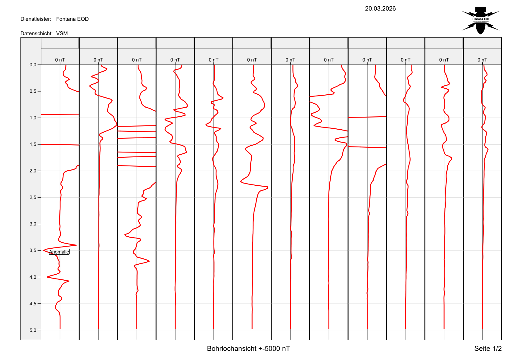
At Unterer Hornbachstaden in Zweibrücken, FONTANA-EOD investigated a documented section of a sheet-pile alignment using borehole surveys. For this section, the report describes a grid spacing of 1.50 metres and an evaluation depth of 5.0 metres. The original documents contain the magnetic profiles of the individual boreholes.
An anomaly marked in the survey data was subsequently investigated. According to the report, no explosive ordnance was found; the partial clearance issued relates to the associated drawings. The example demonstrates the distinction between a survey anomaly and confirmed identification. It does not automatically cover adjoining areas or other project phases.
Scope: the documented section Spundwand 01-2, not the entire shoring alignment.
Downhole magnetometry and deep-ground surveys · Explosive ordnance assessment in Rhineland-Palatinate · Further reference information
Existing documents on suspected ordnance are compared with foundations, wall alignments, excavations and temporary ground interventions. These include temporary shoring and working pits. Relocated structural boundaries may affect zones not covered by an earlier report.
Compare documents with the entire installation volumeFor piles and anchors, the entry point, diameter, inclination, length and orientation are required. The investigation must match the actual volume affected by the planned ground intervention. Limitations caused by existing structures, utilities or lack of access are taken into account when selecting a method.
Assess depth-related investigationMethods are not interchangeable because they detect different physical properties and cover different working volumes. Their combination follows the structural geometry and the project decision required.
Assesses historically substantiated suspected ordnance within the structural corridor.
It does not provide a technical investigation of present-day pile, anchor or shoring locations.
Can detect ferromagnetic anomalies in open areas.
Existing reinforcement, sheet piles and utilities may severely limit its use around structures.
Records electromagnetic responses from conductive objects and can supplement investigation of suitable subareas.
The target object, depth and technical installations determine what conclusions can be drawn.
Shows reflections at material and structural boundaries and can provide information on existing structures or layers.
A reflection does not uniquely identify explosive ordnance.
Investigates defined pile, borehole, anchor and shoring volumes at depth.
Survey geometry and subsequent installation must match precisely at each point or along each axis.
In a technically suitable explosive ordnance survey alongside construction, each working layer is surveyed using technical equipment and assessed. Controlled removal in layers and supplementary visual inspection then follow; these steps are repeated down to the agreed excavation base. Simply watching excavation is insufficient.
Excavation layers, hold points, authority to issue instructions, communication routes and documentation are specified in the work instruction before work starts. Uninvestigated depths and inclined anchor and foundation corridors remain separate investigation tasks.
Reliable work coordinates structural design, specialist foundation engineering, surveying and the construction sequence. All parties must use the same element geometry and drawing revision.
FONTANA-EOD first establishes which information is required for each structural element. Areas, piles, shoring, anchors and excavation zones are not combined into a blanket status for the structure.
Method selection takes account of the survey objective, depth, ground, existing structures, utilities and accessible working space. Technical limitations are identified at the planning stage so that later construction phases include suitable supplementary work.
During fieldwork, element identifiers, surveying and datasets remain linked. Changes to the drawing revision are checked against previous investigation results before the affected ground intervention.
The report provides a usable conclusion for the specific construction stage. Unresolved zones and further measures are described so that structural designers and site management can incorporate them into programme and construction planning.
For structures involving several specialist work packages, it is agreed in advance who is responsible for formally communicating changes to piles, anchors or shoring to the explosive ordnance specialist designer. Even short-notice changes are communicated before the affected ground intervention.
Quality assurance also includes comparing planned points with those actually installed. This checks whether a documented survey point can be assigned to the structural element actually constructed.
Foundations, piles, anchors, shoring and excavations each receive their own investigation reference.
Geometry, surveying and construction are related to the same revision.
Technical interference and lack of access are assigned a defined follow-up phase.
Survey conditions, deviations and checks remain traceable for each structural element.
Additional or relocated elements are reassessed before installation.
The conclusion clearly applies to the structural element, depth and construction stage.
Temporary shoring, site access and excavations may disturb the ground before the actual foundation work. Their investigation requirements are coordinated with the construction sequence in good time so that these works do not begin outside the areas and depths considered so far.
Reports and construction drawings use the same element identifiers and level references. Unresolved areas remain assigned to the relevant foundation, anchor or wall section. Changes to length, inclination or location are reassessed by specialists before implementation.
Interfaces between the client, lead designer, structural designer, specialist foundation contractor and explosive ordnance specialist designer must be established before construction. Public authorities perform separate tasks depending on the project location and findings.
Defines the project objective, structural scope, programme and required documentation.
Provides existing background information and ensures coordinated commissioning of specialist services.
Coordinates the structure location, traffic space, construction phases and ancillary installations.
Changes are distributed to all specialist parties with a clear drawing revision.
Define foundations, piles, shoring, anchors, depths and installation methods.
These data form the technical basis for point- and alignment-specific investigation.
Construct the excavation, piles, shoring and anchors to the agreed geometry.
Deviations and additional measures are reported before ground disturbance.
Assesses the suspected hazard and methods, carries out the commissioned service and documents results and limitations.
The conclusion remains restricted to the agreed structural area and depth range.
In Germany, the ordnance disposal services of the federal states and the locally competent authorities carry out hazard-response and find-management duties. Their involvement is established for the project location; outside Germany, local responsibilities apply.
The local public order authority and, where applicable, the building authority are involved according to their project-specific tasks. Conditions and contacts are assigned to the actual construction section. If ordnance is found, the responsible authorities determine the next steps.
Deep foundation and shoring work can introduce substantial mechanical loads into the ground. Risk assessment, qualifications, methods and documentation are therefore related to the specific structural volume before construction.
In Germany, § 7 SprengG concerns the commercial authorisation for activities requiring authorisation; § 20 SprengG concerns the certificate of competence of responsible persons. Under § 1b SprengG, searching for found munitions also counts as handling them. The requirements applicable to the project depend on the activity actually commissioned and the allocation of responsibilities.
DGUV Information 201-027 supports risk assessment and the specification of protective measures for explosive ordnance clearance work. Clients and designers must consider relevant hazards during investigation, specification of services and construction planning.
The Baufachliche Richtlinien Kampfmittelräumung contain requirements for historical and technical investigation, clearance concepts, procurement and documentation within their defined federal remit. Their application to the specific civil engineering project is established separately.
For driving, piling, drilling and shoring works, the relevant depth must be assessed by specialists before ground intervention. A near-surface assessment must not be applied to deep structural elements without further assessment.
If an unexpected suspicious object is encountered, stop work immediately in the affected area. Do not touch, move, clean or expose the object further. Leave the danger area and keep others away without putting yourself at risk. In Germany, notify the police immediately on 110; outside Germany, use the local emergency contact procedure. The responsible authorities determine the next steps. Then inform site management.
Temporary construction stages are also included in the risk assessment. Demolition, open excavations, dewatering, live traffic, cranes and drilling rigs, and restricted escape routes may require different protective and communication measures from those for the structure's eventual completed condition.
The First Ordinance to the Explosives Act (1. SprengV) includes, among other things, requirements for specialist knowledge and state-recognised training courses. For civil engineering structures, qualifications and responsibilities are linked to the investigation or clearance scope actually commissioned.
DGUV Rule 113-003 concerns the dismantling or destruction of explosives or corresponding objects and also includes the disposal of found munitions. It applies according to this field of activity; it does not replace a risk assessment specific to the planned ground intervention.
Qualifications, appointment and remit must match the specific scope of activities.
The excavation, specialist foundation equipment, energy input, utilities, traffic and escape routes are assessed together.
The structural volume, investigation geometry, data handover and quality checks are clearly described before construction.
Hold points, responsible persons and local reporting procedures are prepared for the construction sequence.
Structural elements, depths, methods, drawing revisions and documentation objectives are specified in a form suitable for tendering.
Setting-out, utilities, access, equipment and current geometry are checked against the documentation.
If an unexpected suspicious object is encountered, stop work immediately. Do not touch, move or expose the object further. Leave the immediate area and keep others away without putting yourself at risk. In Germany, notify 110 immediately; outside Germany, use the local emergency contact procedure.
The documents link structural design, fieldwork and specialist foundation engineering. The structural element, depth and construction stage must match the documented result unambiguously.
The drawing distinguishes foundations, piles, shoring, anchors and ancillary installations according to their actual geometry.
Explore element geometry and depth references
The assessment explains which structural elements require more detailed technical investigation.
Review historical evidence of suspected ordnance
Deep foundations and shoring receive their own investigation geometry.
Investigate deep foundations and shoring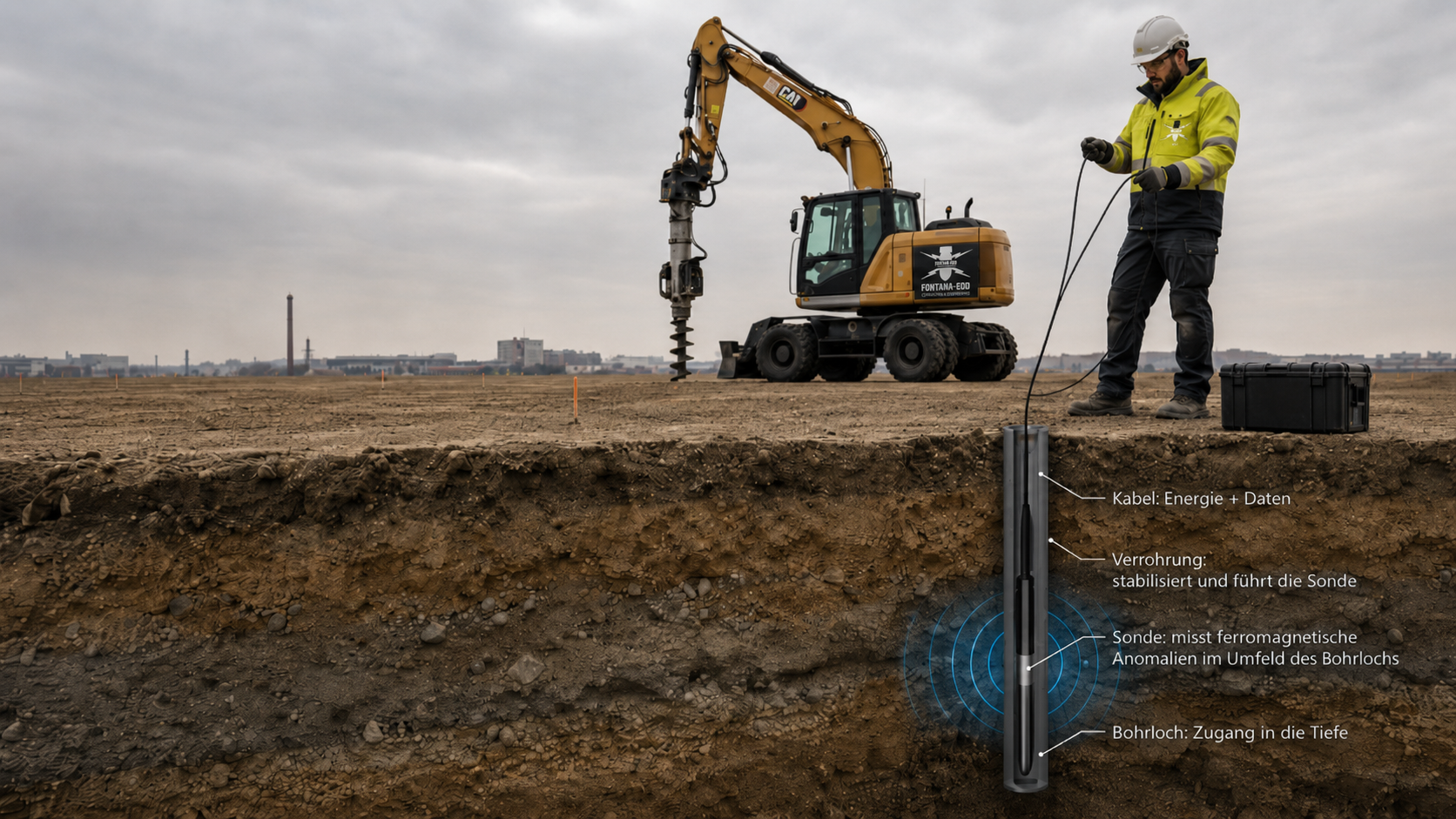
Casing and interference are included in the specialist evaluation.
Coordinate probe guidance and survey conditions
Hold points and subsequent decisions remain linked to the construction stage.
Provide specialist supervision of excavation
The handover shows the stage reached for each structural element.
Document the structural file and handover
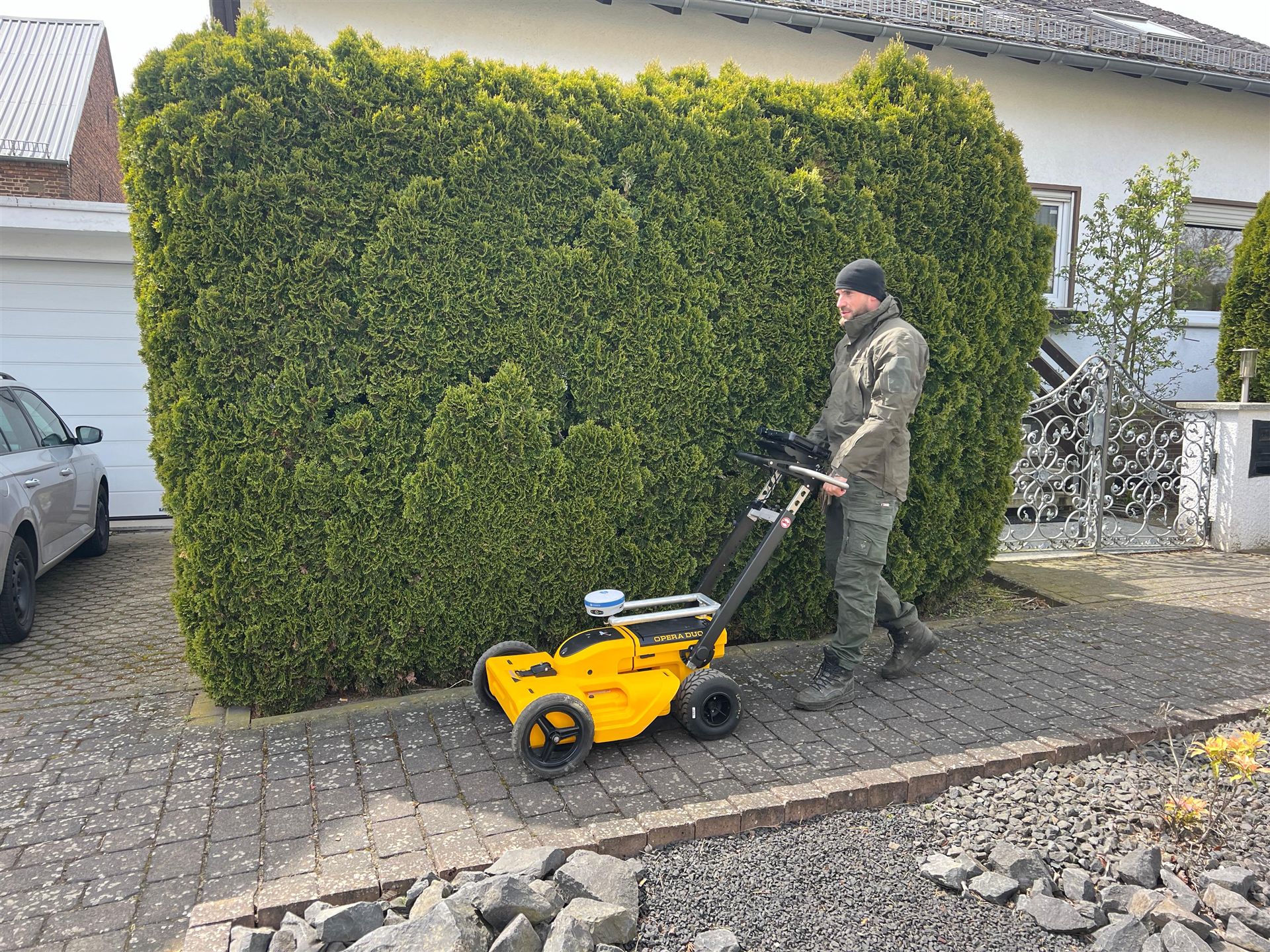
Historical assessment of suspected ordnance, investigation of deep structural elements, detection during construction and documentation are related to the same structural section. For other construction tasks, use the sector overview.
Plan road, sewer and civil engineering works involving crossings, drainage and foundations according to construction section and depth.
Assess civil engineering structures within the road project
Relate historically identified areas of suspected ordnance to the structural alignment, working space and temporary construction stages.
Assess the structural corridor using historical evidence
Investigate piles, shoring and anchors using element-specific point, alignment and depth geometry.
Investigate deep structural elements
Assess whether explosive ordnance detection during construction is suitable for the open excavation zones.
Prepare excavation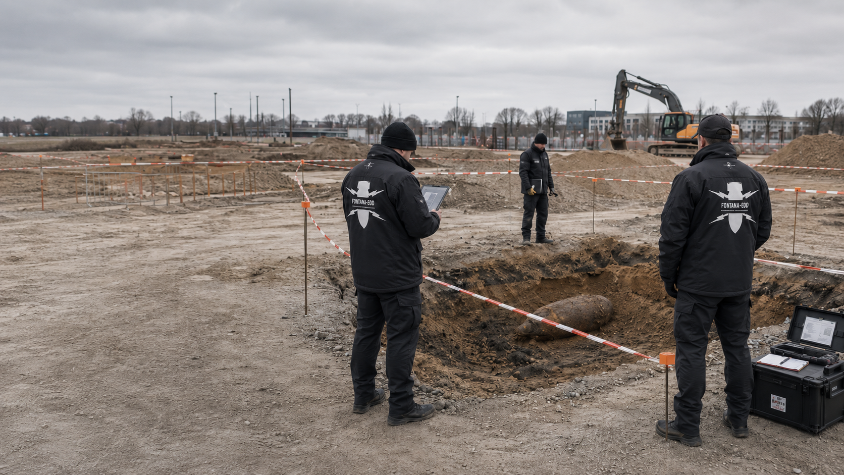
Coordinate recovery of confirmed ordnance with the permitted activities and local responsibilities.
Follow up structural findings
Combine drawing revisions, element schedules and construction-phase status into a verifiable documentation system.
Structure the structural file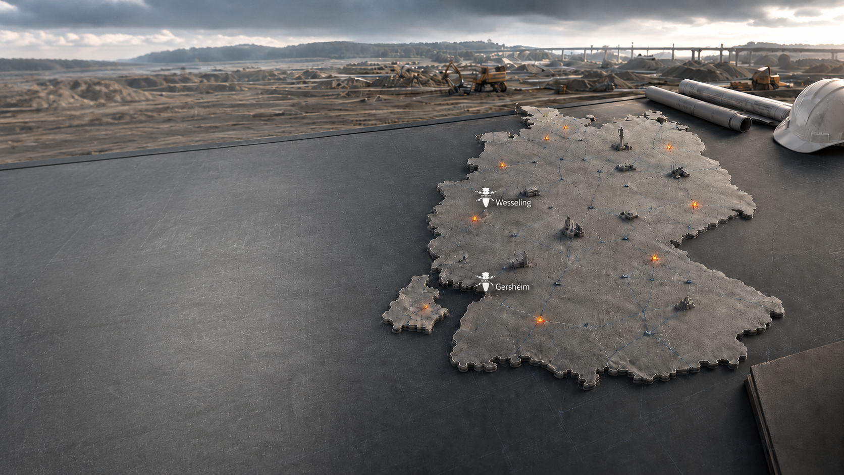
Involve the regional authorities responsible for ordnance finds, emergency response and project communication at an early stage.
Establish local interfaces
Provide complete sections, pile and anchor schedules and construction phases for an initial specialist assessment of construction.
Submit a specific enquiry about your civil engineering structureState the project location, structure designation, wall sections and current element identifiers. Site plans and sections also show laterally extending anchors and temporary working areas. Existing requirements and earlier reports are included with their spatial references; neighbouring structures are shown separately.
An anchor's entry point only partly describes its subsequent course. Compare its inclination, length and orientation with the documented investigation volume as well. A conclusion about the excavation must not be applied to laterally adjoining zones at depth without assessment.
Check evidence against the interventionDemolition, excavation or exposure may reveal previously unknown structural elements. Relate these findings to the current drawing revision and establish whether the investigation arrangement, access or proposed ground intervention needs to be adapted.
Explore the technical principlesTechnical information
How can carriageways, bridges and deep excavations be investigated for ordnance? The brochure explains preparation, suitable survey methods and supervision of earthworks.
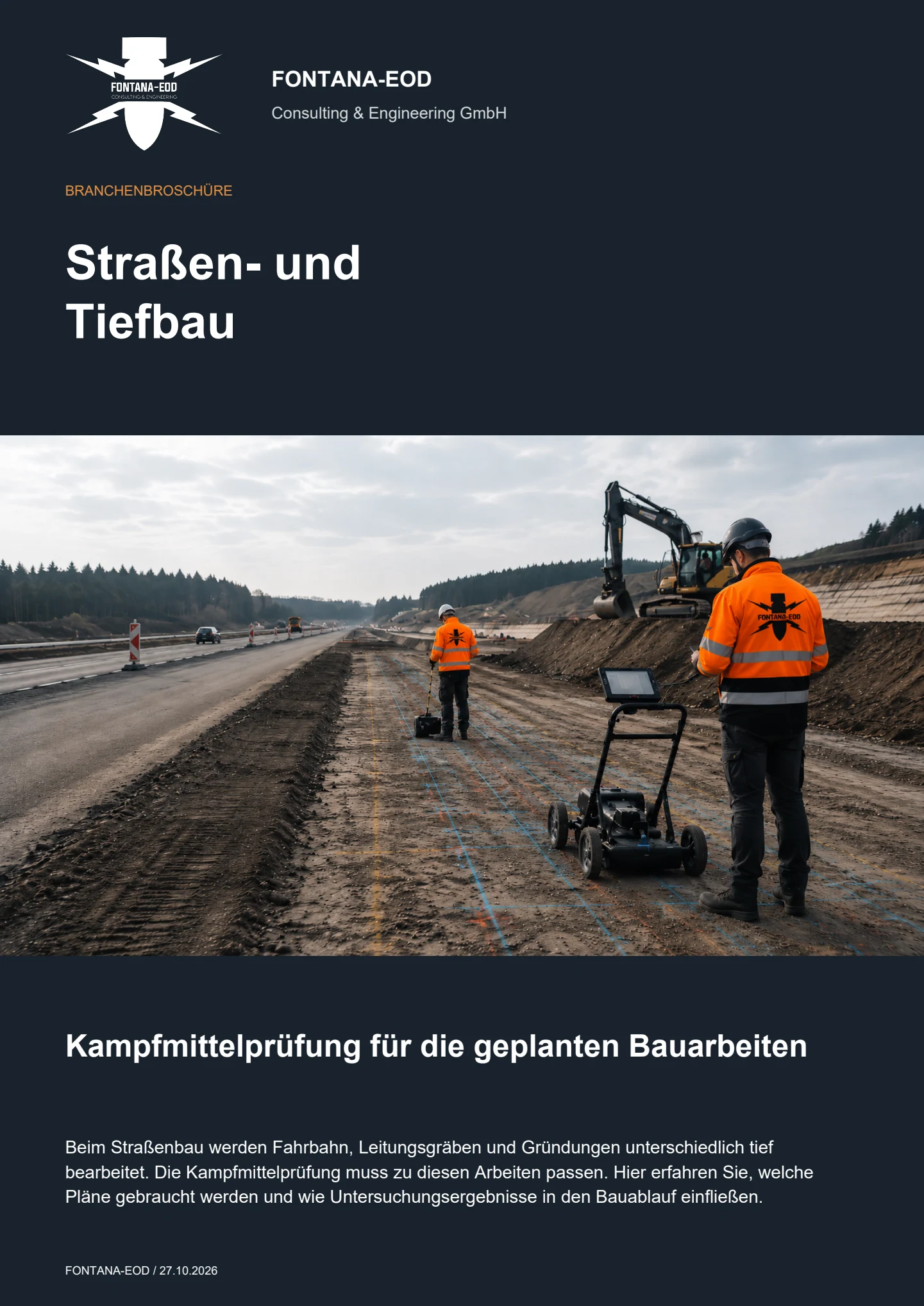
The investigation required is established from existing indications of suspected ordnance and the planned groundworks. Excavations, foundations, piles, anchors, shoring, abutments and boreholes are described by location and depth. The earlier the structural geometry and construction stages are known, the more precisely historical assessment, surface investigation and deep point-specific investigation can be coordinated.
The foundation base, pile or borehole locations, anchor axes, sheet-pile lines, working space behind the wall, drainage, excavation and temporary access road occupy different areas and depths. Each requires its own defined relationship to the suspected hazard, survey feasibility and subsequent construction.
Effort, duration and cost depend on the number and geometry of structural elements, intervention depths, installation methods, interference sources and accessibility. Construction phases, dewatering, equipment access and the required documentation affect the sequence. New anchors, replacement piles or changed shoring alignments may require additional investigation. Structural drawings, sections, schedules of structural elements and the proposed construction sequence are needed for costing.
Required documents include site and structural drawings, sections, foundation and shoring schedules, borehole lists, anchor or pile axes, target depths, installation methods, construction phases, utility and as-built drawings, ground investigation data and any existing aerial photograph assessments or earlier survey reports.
Information and requirements from authorities are supplied with their date, complete appendices and geographical scope. In Germany, the competent ordnance disposal service, local public-order authority and, where relevant, building-control authority are identified for the project location; outside Germany, local responsibilities apply.
Reinforcement, existing foundations, sheet piles, utilities, ducts and technical installations can obscure survey data and restrict working space. Known installations are mapped before methods are selected. Zones that have not been adequately investigated are marked on the drawing. The possible time of access and a suitable supplementary method are established for these zones.
If existing structures, reinforcement or lack of access limit preliminary investigation, the technical suitability of explosive ordnance detection during construction is assessed. Each working layer is surveyed and evaluated using technical methods before controlled removal in layers with supplementary visual inspection. The steps are repeated down to the agreed excavation base. Excavation layers, equipment use, hold points, lines of instruction and documentation are established before work starts. Necessary investigations and protective measures are also planned before ground disturbance during breaking out or demolition; deep piles, anchors and shoring remain separate investigation tasks.
The report links structural identifiers, element geometries, areas and depths investigated, survey and borehole data, known interference sources, findings, areas that could not be investigated and follow-up measures. It must show which structural elements and construction stages are covered and which changes require supplementary work.
Stop work immediately in the affected area. Do not touch, move, clean or expose the object further. Leave the danger area and keep others away without putting yourself at risk. In Germany, notify the police immediately on 110; outside Germany, use the local emergency contact procedure. Then inform site management.
An initial enquiry should show which structural elements will be constructed, how deep they will extend and at which construction stage investigation can take place.
Planned temporary works such as temporary anchors, auxiliary piles or assembly foundations also belong in the documents where they affect ground that has not yet been assessed.
For initial scheduling, it should be clear when demolition, exposure, surveying and specialist foundation work will take place. This allows supplementary investigations to be linked to the construction stage accessible at the time and unnecessary stoppages to be avoided. The proposed sequence of shoring, excavation and main foundation work is also linked to the required documentation. Necessary investigations and handovers of results for individual structural elements are included in the construction programme.
Provide the project address, site plan, structure number, axes, sections, construction phases and current revision.
Temporary construction stages and ancillary areas are marked where they entail their own ground interventions.
Point and alignment schedules, coordinates, diameters, depths, inclinations, installation methods and planned auxiliary boreholes are required.
Any possible options or alternative tenders should also be clearly described in spatial terms.
Include utility drawings, existing foundations, ground investigation records, historical assessments, earlier documentation and the construction programme.
Dewatering, traffic, demolition and restricted access affect method selection.
A site plan, structure type, foundation or shoring method, maximum depth, construction phase and existing indications of suspected ordnance are often sufficient for an initial assessment. These allow the areas and depths requiring technical investigation to be identified.
For complex structures, the work can be divided into the excavation, pile or shoring points and later demolition stages. Documentation remains linked to the same element identifiers throughout all phases.
For several structural or construction sections, priorities and firm decision dates should be stated. This allows the explosive ordnance investigation to focus on the points needed first for demolition, shoring, trial piles or the start of the main foundation work.
Axes, sections, excavation, foundations and ancillary areas.
Piles, anchors, shoring, borehole points and target depths.
Demolition, accessibility, traffic, dewatering and dates.
Basis for design, procurement, specialist foundation work or the project file.
Whether historical aerial photograph analysis, explosive ordnance surveying, surface surveying using GPR, magnetometry or TDEM, deep-ground surveys, downhole surveys, excavation supervision, area clearance or ordnance recovery is needed depends on the location, ground disturbance, depth, ground and existing documents. An early ordnance assessment provides clarity for tendering, programming, occupational safety and construction.
FONTANA-EOD combines its Section 7 SprengG licence, specialists holding Section 20 SprengG certificates of competence, suitable survey and clearance methods, and traceable documentation. Send the site plan, depth of ground disturbance, construction phase and existing documents for an initial technical assessment.


