Project pathway
The quickest route to the right decision.
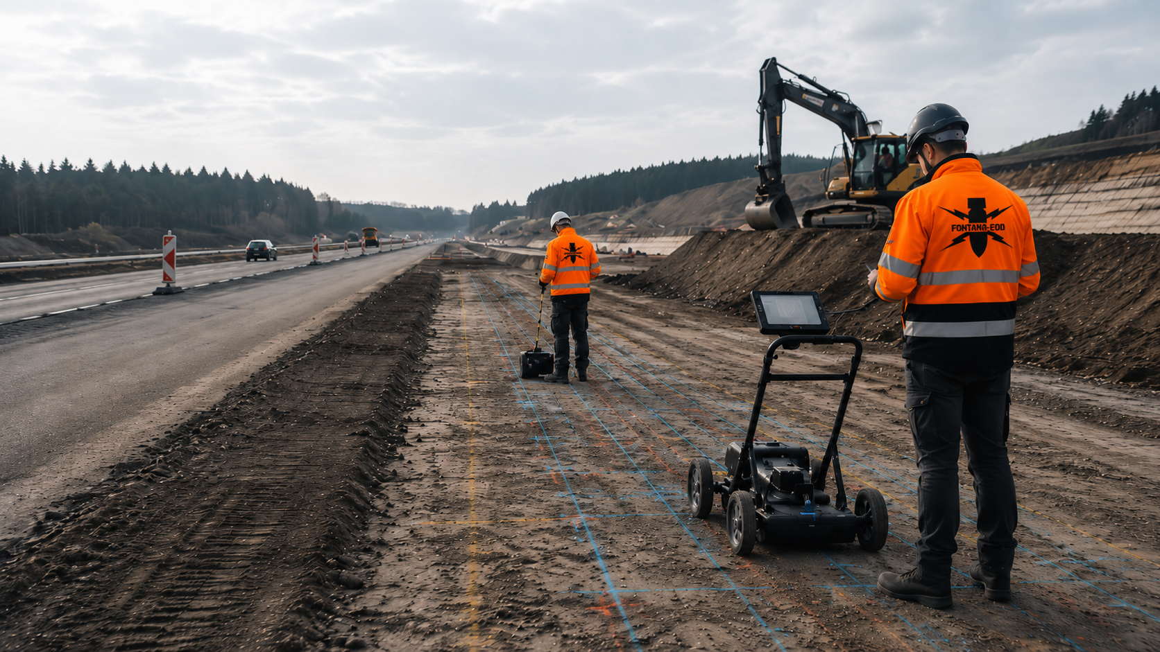
When a transport junction is altered, ramps, junction arms and foundations are checked against the existing suspected hazard. FONTANA-EOD plans suitable investigations according to intervention depth, construction phase and survey conditions. Send the junction plan, traffic phases and depth lists so that the required services and documentation can be defined before the respective groundworks.
Separate ramps, arms and structures.
Assign masts, gantries and shoring.
Document subareas and handovers.
Before a transport junction is built or altered, investigation requirements are established from existing indications of suspected ordnance and planned groundworks. Ramps, junction arms, structures, utilities and foundations are considered by their location and depth at each construction stage. Traffic management and existing installations also determine when an area is accessible and which method can be used there. The documentation assigns results and outstanding areas to the respective subarea and construction phase.
The scope of services for ‘A60/A63 Mainz -Süd motorway interchange – northern bridge and final works Mainz / Deutschland’ included downhole magnetometry.
Service period: 2025-10
Service areas:Downhole magnetometry / deep-ground survey
View project details · Deep-ground and downhole surveys · Project location: Mainz
The scope of services for ‘A4 central reservation at the interchange’ included ordnance specialist supervision of groundworks.
Service period: 2024-11
Service areas:Ordnance specialist supervision of groundworks
View project details · Ordnance specialist supervision of groundworks
A transport junction consists of area-wide carriageways, linear ramps, deep foundations and areas accessible only during certain phases. These ground volumes are planned separately.
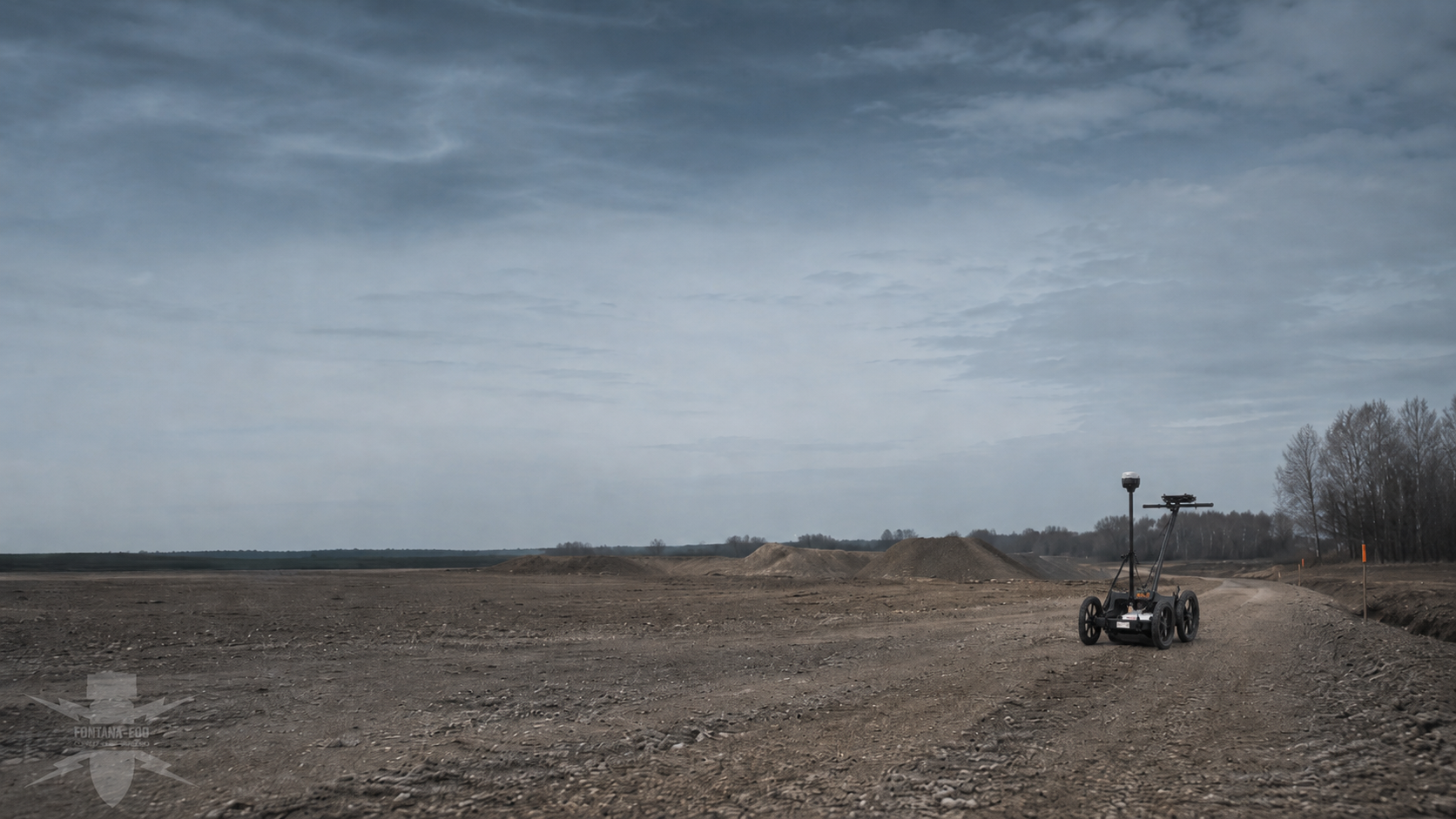
Turning lanes, widenings and new carriageway edges alter the near-surface ground volume and may extend laterally into previously undisturbed ground.
Survey areas, asphalt and demolition stages and deep edge points are described separately by junction arm and construction phase.
Turning lanes and carriageway widenings are recorded with their actual demolition and soil-replacement boundaries; road-marking or lane plans alone are insufficient.
Investigate junction arms and wideningsEntry and exit ramps, weaving lanes, slopes and drainage form long, curved ground volumes with varying depths.
Investigations and reports are assigned to chainage, the ramp alignment and individual structures.
For long ramps, chainage and construction sections are selected so that drainage, slopes and possible structures retain the same spatial documentation reference.
Assess ramp sections with specialist inputThe circulating carriageway, inner ring, central island, crossing points and edges have different structures and technical installations.
Area-wide surfaces, drainage, lighting and deep fitting points each receive their own investigation geometry.
Central islands may contain utilities, foundations or former traffic areas. Before alterations, the surface, structure and planned depths are considered separately.
Investigate roundabout areas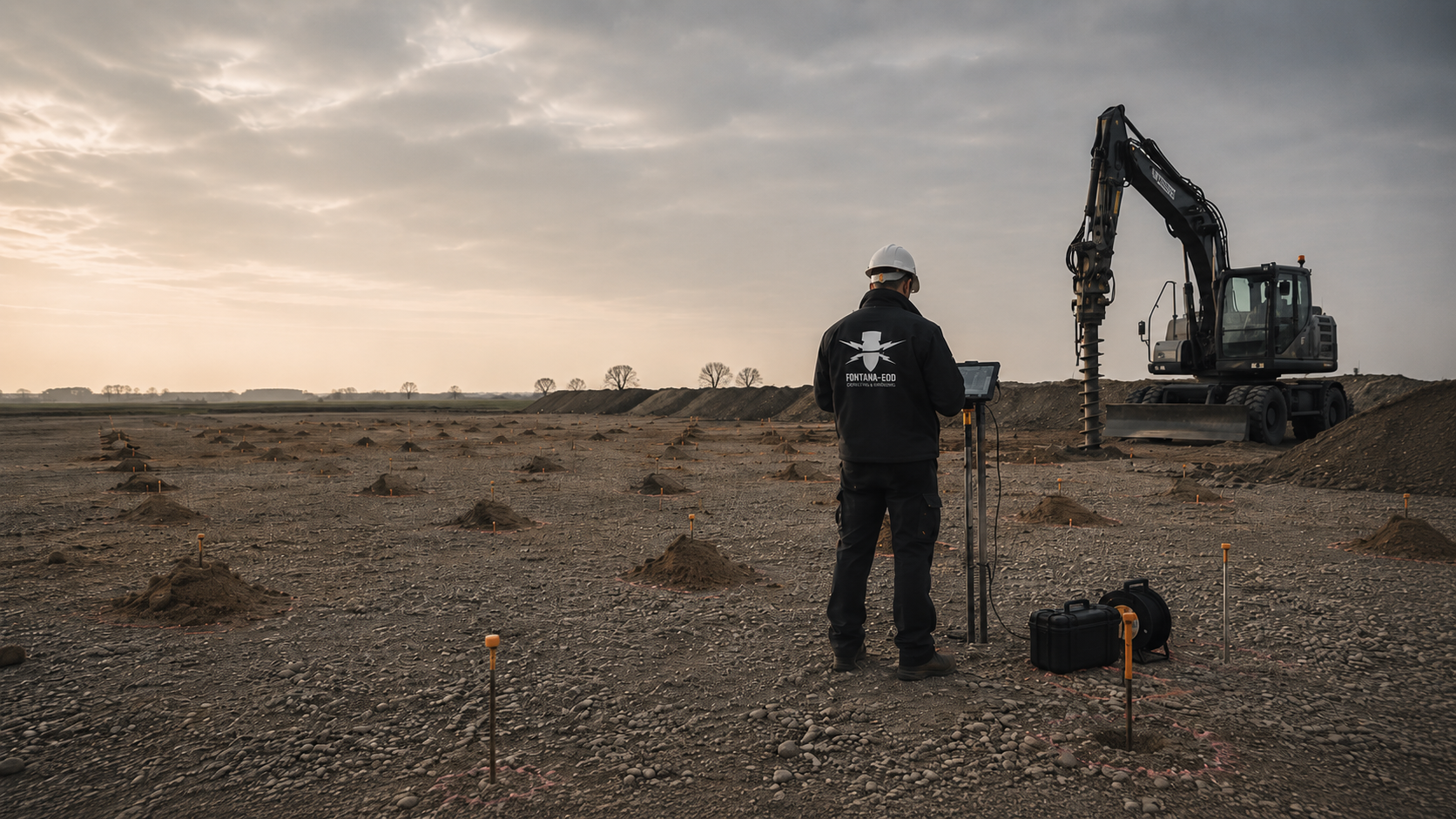
Gantries, cantilever arms, large signs and lighting masts require localised foundations outside or between traffic areas.
Coordinates, foundation size, target depth and installation method are used to establish the investigation required for the intervention.
For gantries and large signs, crane standing areas and temporary assembly areas are also considered where temporary foundations or groundworks are planned there.
Investigate gantry and mast foundationsSwales, stormwater sewers, shafts, culverts and control cables often cross ramps or run along carriageway edges.
Trench alignments and excavations are planned separately from the traffic surface alone and assessed by depth and construction stage.
For crossings beneath ramps or junction arms, launch pits, reception pits, bore paths and open excavations are shown separately on the plan.
Investigate drainage and utility volumesGrade-separated junctions connect ramps with abutments, retaining walls, shoring and deep foundations.
Approach areas, excavations, piles and anchors are investigated for each component, rather than inferred from the carriageway area.
At grade-separated junctions, structure approach areas and unobstructed ramp sections are not combined because surveyability and the depth investigation required may differ significantly.
Clarify structure and depth volumesGeometry and access change with the traffic phase. Investigation status must therefore remain linked to plan revisions and construction stages.
Early options differ in land requirements, structures, ramp length and interventions into existing roadside areas.
The historically suspected hazard and expected investigation effort can be included in the comparison of options.
The comparison identifies not only land requirements but also the number of deep individual points and proportion of technically difficult-to-access areas.
Historically assess the optionsJunction arms, ramps, islands, retaining walls, gantries and utility alignments are related to the suspected corridor.
Unresolved geometries remain identified as design assumptions until sufficiently defined for tendering and fieldwork.
For every design revision, it remains traceable whether additional ramps, islands or technical installations trigger new explosive ordnance investigations.
Have the design geometry checkedTemporary diversions and traffic shifts create additional work areas used only temporarily.
These areas are assessed separately for groundworks, surcharge loading, drainage and subsequent removal.
Temporary traffic areas are assessed with their own road structure, excavation and later removal; they are not automatically treated as part of the final geometry.
Organise traffic phases and investigation statusTraffic signals, lighting, communications, drainage and utility services are linked to point and trench lists.
Missing or contradictory existing-condition data is clarified before fieldwork; remaining uncertainties are identified.
Coordination brings utility and point lists together in a common spatial reference so that masts, shafts and cable alignments are not planned independently.
Coordinate utility and point listsAreas, depths, methods, construction stages, qualifications and documentation are described so that quotations cover the same scope of services.
Time-critical subareas are prioritised without reducing minimum technical requirements.
With tight schedules, areas and foundations critical to construction are investigated first, while less urgent areas receive a clear follow-up date.
Prepare the service specificationRamps, junction arms and structural areas investigated are documented by section and handed over to subsequent trades.
Plan changes or additional points are checked against the existing investigation status before execution.
Before handover, the traffic phase and actual component geometry executed are checked against the documented investigation status.
Document subareas and handovers traceablyThe appropriate service depends on the subarea and subsequent intervention. Different requirements for carriageway areas, foundations and later construction phases are identified in the service specification.
Undeveloped or cleared subareas can be investigated by area where the surface and ground are suitable for the selected method.
The survey grid and working width are related to the carriageway, roadside areas and ancillary facilities.
Unobstructed areas are combined only insofar as the surface, ground and expected target objects permit a comparable survey strategy.
Investigate area-wide new-construction sectionsTraffic infrastructure, utilities, shafts, reinforcement and earlier excavations create complex interference conditions.
Areas that can be surveyed and areas whose data cannot be evaluated reliably are distinguished and assigned different follow-up measures.
At surfaced junctions, a short test section may help assess data evaluability under actual installation and traffic conditions before the main survey.
Assess surfaced junction areasSign gantries, traffic signals, lighting and gantry frames involve localised interventions at greater depths.
Each location is assigned its own investigation task using coordinates, foundation geometry and target depth.
For deep points, it is also checked whether construction equipment and drilling methods occupy lateral working space or additional auxiliary points.
Investigate deep equipment foundationsSheet piles, bored piles, anchors and retaining walls create linear or inclined depth volumes.
Alignment, direction, embedment depth and installation method determine survey planning.
Inclined anchors and offset shoring alignments are considered in three dimensions because their position at depth cannot be read from the surface alignment alone.
Investigate shoring alignments and anchorsOngoing traffic, existing carriageways or structures may block subareas until a later demolition stage.
For these areas, the possible investigation time and suitable method are established. An explosive ordnance survey alongside construction is considered only where technically suitable for the planned intervention.
Areas accessible later receive a defined investigation time and clear responsibility for creating the required working conditions in the tender documents.
Include remaining areas in construction phasesSurvey anomalies and specific findings are linked to the junction arm, ramp, construction phase and traffic arrangement.
The follow-up decision considers a safe work stoppage, specialist investigation and regional responsibilities.
If a suspicious object is encountered, neighbouring areas must not continue to be used solely on the basis of a boundary chosen by those on site. Further action is coordinated with the responsible authorities.
Clarify the findings procedure for the junctionThe documentation must remain clear even with several ramps, structures and traffic phases. Location, method and statement limitations are recorded together.
Alignments, ramps, junction arms, islands, chainage and construction sections form the spatial reference.
Point objects and structures additionally receive clear identifiers.
The site plan distinguishes permanent structures, temporary traffic areas and working volumes used only during construction, each with its own status.
Historical assessment, information from authorities, earlier finds and existing-condition documents are recorded with their scope.
Unresolved areas remain clearly identified as separate project tasks.
Historical statements are related to the actual subareas so that suspicion is not extended indiscriminately to the entire junction.
The survey system, grid, surface, traffic conditions, utilities and technical sources of interference are documented for each subarea.
This shows why methods had to change or be supplemented between sections.
Survey conditions and traffic restrictions are recorded where they affect the grid, line layout or depth achievable.
Masts, gantries, shafts, shoring and anomalies share a common identification structure.
Status and follow-up measures are maintained consistently across plans, field records and the report.
Point status and component revision are linked so that an earlier investigation status is not mistakenly retained after relocation.
Areas carrying traffic, occupied by structures or obscured by technical interference are shown with georeferencing.
They are not included in a general statement for the junction.
Areas that cannot be investigated are distinguished by cause: lack of access, technical interference, retained existing structures or installations, or a construction stage not yet reached.
The report describes which subarea was investigated, at which construction stage and to what depth.
Subsequent trades receive a clear basis for the next intervention.
The conclusion identifies the usable ground volume and the conditions under which the next construction phase may begin.
A junction project generates numerous plan revisions and partial handovers. The project file assigns plans, survey data and decisions to the respective subareas and construction phases.
Site plans, traffic phases, structural plans and point lists are recorded with their dates and revisions.
This makes it possible to trace which geometry underlay each field assignment.
The plan register also includes traffic phase and diversion plans where these change access or the location of temporary interventions.
Ramps, junction arms, islands, gantries, shafts and retaining structures receive clear IDs.
The identifier links survey data, photographs, findings and handovers.
Component identifiers are combined with a ramp or junction-arm reference so that similar masts and shafts remain clearly distinguishable.
Raw data, survey lines, any drilling records, investigation depths and evaluations are organised by subarea and method. Where exposure or clearance work has actually taken place, the corresponding findings and clearance records are included.
Original data and processing revisions are retained separately.
In addition to the subarea and method, survey data records the construction stage because the same location may have different interference conditions in later phases.
Anomalies are recorded with their location, assessment, investigation status and planned follow-up measure.
Completed and outstanding points remain clearly distinguishable.
The measures register documents whether an anomaly is to be surveyed again, investigated at a specific point, exposed or investigated during a later construction phase.
Traffic diversion, demolition, surveying, foundation work and partial handover are shown in an overview that can be updated.
This allows site management to identify the ground volume usable at each stage.
Partial handovers are updated so that outstanding edges and deep points still awaiting investigation remain visible as construction progresses.
Reports, plans, point lists, limitations and communication records are handed over in the agreed structure.
Later changes can receive a new specialist assessment using the subarea identifier, construction stage and documented investigation geometry.
The final project file shows which construction stage the results apply to. Before later alterations, the existing investigations are checked for coverage of the new intervention.
The process is adapted to the design revision, traffic phases and critical installation dates. Investigation, evaluation and handover of results are scheduled before each construction section.
Junction arms, ramps, structures, point objects, construction phases and the required statement are clearly described.
Historical information, existing-condition plans, utilities and earlier investigations are related to the current geometry.
Carriageways, islands, drainage, masts, gantries, shoring and excavations receive their own investigation geometries. The sequence of necessary investigations and protective measures is also defined before groundworks during surface removal or demolition.
Area surveys, deep-ground surveys and explosive ordnance surveys alongside construction are assessed for their suitability for each intervention and planned according to construction phases.
Alignments, points, exclusion areas, traffic management, equipment access and communication are agreed before fieldwork.
Surveys and necessary depth investigations follow the agreed area and point reference. Methods and actual survey coverage are documented; deviations from the plan receive a follow-up decision.
Survey values, known installations, anomalies and limitations are checked for plausibility against the component and construction phase.
The report, site plan, point status and outstanding measures are prepared for site management and subsequent trades.
Junctions combine curved ramps, area-wide carriageways, deep point foundations and linear shoring. A total area without component references is an insufficient basis for specifying services.
For each junction arm and ramp, the alignment, chainage, width, demolition boundary and intervention depth are recorded. Point objects and shoring receive additional geometric details.
Temporary traffic areas may occupy different ground volumes from the final arrangement. Temporary masts, drainage and diversions are also considered where they involve groundworks.
If traffic or structural planning changes, it is checked whether new points and areas remain within the documented investigation scope.
The alignment, start of widening, carriageway width, roadside area and demolition boundary determine the area-wide ground volume of the works.
Temporary and final geometries are recorded separately.
For each widening, the area between the existing and new alignments is shown separately because it often involves previously undisturbed ground.
Chainage, ramp course, embankment or cutting and drainage affect access and survey equipment.
Laterally offset work areas are included in planning.
Ramps are considered with their actual longitudinal gradient so that elevation and planned groundworks remain traceable along the entire chainage.
Each point requires coordinates, foundation size, target depth and installation method.
Relocated points are checked for investigation coverage before execution.
For gantries and traffic signals, ducts, cable feeds and control cabinets are also recorded as separate interventions.
Alignments, embedment depths, pile grids and anchor inclinations define linear and inclined depth volumes.
A general area investigation does not automatically cover these geometries.
For retaining walls, a distinction is made between the foundation, wall alignment, tie-back anchors and temporary excavation.
Trenches, shafts, culverts and control cables receive their own line and depth references.
Existing-condition data is assessed for currency and positional accuracy. Existing plans and utility locating results are compared with survey areas and excavations; known installations support plausibility checks. Traffic control, telecommunications installations and older road structures are considered. Unclear areas or areas obscured by technical interference are shown on the plan and assigned a suitable follow-up investigation.
Drainage structures receive their own depth and location reference where they lie outside the carriageway or in ramp gores.
Each construction phase changes access and, in some cases, the ground volume of subsequent works.
Investigation status is updated when plans change, temporary works are added or points are altered.
Each plan revision is checked to establish whether only traffic management has changed or whether the ground volume relevant to explosive ordnance has changed as well.
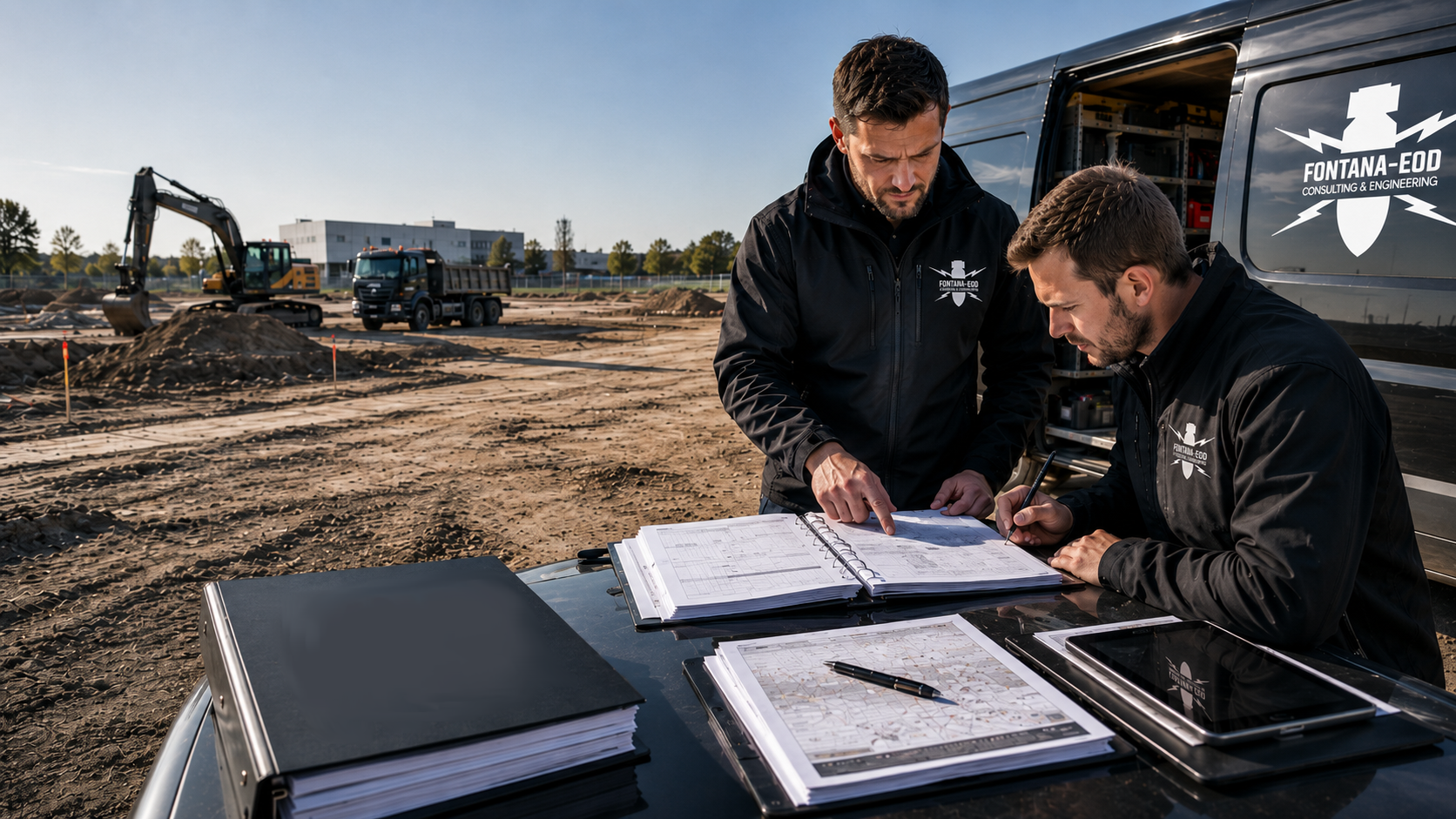
Existing documents are compared with every planned subarea. This includes widened edges, temporary carriageways and drainage facilities where groundworks are planned. A report for the existing carriageway alone does not describe these additional volumes.
Compare documents with ramps and junction armsSign gantries, traffic signals, retaining structures and shafts may extend deeper than the road structure. Method selection considers their individual location and depth, as well as utilities, installations and access achievable in each construction phase.
Assess depth-related investigationHistorical assessment, area surveys, point-specific investigations and services alongside construction fulfil different tasks. They are combined according to the actual construction geometry.
Establishes suspected areas and priorities within the junction.
It does not establish which objects are present today or provide automatic release.
Historical sources are evaluated for the individual junction arms and ramps so that suspected areas are not extended indiscriminately to the entire project.
Investigates accessible carriageway, edge and open areas using a suitable method.
Reliable coverage depends on the surface, technical interference, target object and subarea actually surveyed.
Surface methods are suitable only for technically accessible subareas and require a clear reference to subsequent demolition and excavation.
May show structural reflections and installations in suitable surfaced areas.
The evaluation is checked against existing-condition data. Whether the planned depth range is covered sufficiently requires a separate assessment.
Reflections may be caused by layer boundaries, utilities or other installations. Ground structure and electromagnetic properties also determine which structures can be evaluated; this does not automatically identify explosive ordnance.
Investigates defined foundation, mast, shoring and borehole points.
Every statement remains limited to the documented point and depth geometry.
Deep-ground and borehole surveying are related to gantries, masts, shoring and piles with their respective target geometries.
In a technically suitable explosive ordnance survey alongside construction, each working layer is surveyed using technical equipment and assessed. Controlled removal in layers and supplementary visual inspection then follow; these steps are repeated down to the agreed excavation base. Simply watching excavation is insufficient.
Excavation layers, hold points, authority to issue instructions, communication routes and documentation are defined in the work instructions before work begins.
Excavation monitoring is linked to specific remaining areas and construction phases so that its statement remains spatially limited and verifiable.
Recovery of confirmed explosive ordnance is coordinated with the permitted scope of activity and local responsibilities.
The regional reporting and responsibility route remains decisive.
Individual suspected points are professionally exposed and assessed. Exposure and subsequent recovery are documented with the scope actually carried out.
Magnetometry detects magnetic anomalies, particularly those caused by ferromagnetic objects. On suitable unobstructed ramp and edge areas, it may provide a location-specific basis for anomaly assessment. Safety barriers, vehicles, reinforcement and other iron masses may obscure signals. Survey coverage and interference zones are documented separately; a signal does not identify an object.
TDEM detects time-dependent electromagnetic responses from conductive objects. Target size, depth, survey geometry and technical surroundings limit the achievable statement. Utilities, reinforcement and metal installations may affect evaluation. Results are checked against existing-condition information and the basis for suspicion. Whether a foundation volume is covered sufficiently is assessed using its actual geometry.
Before work begins, subareas, suitable investigation methods and required documentation are defined. Results are assigned to the areas and depths actually investigated.
FONTANA-EOD relates the service to the specific junction arm, ramp, structure or point scheduled for execution next.
Before fieldwork, the surface, existing utilities, traffic conditions, access and deep components are checked. This establishes a concept that can be implemented realistically.
Plan changes, additional gantries or relocated shoring alignments are assessed against the existing investigation status. Results are not extended without spatial documentation.
Anomalies are communicated with their subarea and construction phase. This allows the project organisation to stop work specifically in the affected area and arrange further steps.
At complex junctions, the investigation sequence is linked to construction phases. Ramps, gantries or drainage areas needed early are prioritised, while later subareas receive a binding follow-up date. This keeps investigation aligned with the schedule without mixing the spatial statements of individual records.
Junction arms, ramps, islands, structures and point objects share a common spatial reference.
Traffic phases and demolition stages are included in method selection and scheduling.
For masts, gantries, shoring and shafts, a separate check establishes whether the required location and depth have been investigated.
Changed ramps, new point objects and plan revisions are systematically checked against the existing subarea status.
Areas obscured by interference or inaccessible areas are mapped and assigned a follow-up measure.
Each handover clearly describes the area, depth and construction phase reference.
For each traffic phase, the accessible ramps, islands and edges are established. Necessary investigations and their evaluation are scheduled so that results are available before the associated groundworks. Later access remains clearly identified as an outstanding task in the construction sequence.
Before a changeover or partial handover, the areas investigated, documented depths and remaining gaps are reconciled with the execution plan. Decisions on traffic and the construction sequence remain with the responsible project organisation.
Junctions combine several specialist designs and often several road authorities or utility operators. Before work begins, responsibility is defined for obtaining missing documents, communicating plan changes and deciding on the next works.
Define the project objective, junction form, construction phases and required decision.
Ensure agreed plan revisions and a consistent data structure.
The project organisation prioritises subareas according to the construction sequence and documents the plan revisions approved for execution.
Translate the project into alignments, ramps, structures, point lists and depths.
Changes are checked against the explosive ordnance investigation status.
Traffic planning translates construction phases and temporary arrangements into areas actually accessible for surveying and subsequent handover.
Provides existing-condition data and technical requirements for cables, shafts, signals and drainage.
Discrepancies are clarified before tendering or fieldwork.
Specialist coordinators reconcile utility points, signal locations and drainage with the current junction design.
Implement construction phases, work areas, hold points and reporting routes.
Additional points or changed excavation volumes are reported before execution.
Before each intervention, site management checks whether the execution geometry corresponds to the documented investigation status.
Assesses the suspected hazard, methods and documentation and carries out the commissioned services by section.
Results and limitations are related to the subarea and construction stage.
FONTANA-EOD brings survey and point data together with construction stage and subarea identifiers.
In Germany, the ordnance disposal services of the federal states and the locally competent authorities carry out hazard-response and find-management duties. Their involvement is established for the project location; outside Germany, local responsibilities apply.
Involvement follows the project location and specific find situation.
The local public order authority and, where applicable, building control authority are involved in their project-specific roles. Conditions and contacts are assigned to the actual subarea. If ordnance is found, the responsible authorities determine the next steps.
Qualifications, risk assessment and work organisation are related to the traffic area, construction phase, activity and project location.
In Germany, § 7 SprengG concerns the commercial authorisation for activities requiring authorisation; § 20 SprengG concerns the certificate of competence of responsible persons. Under § 1b SprengG, searching for found munitions also counts as handling them. The requirements applicable to the project depend on the activity actually commissioned and the allocation of responsibilities.
DGUV Information 201-027 supports risk assessment and protective measures for explosive ordnance clearance. The Baufachliche Richtlinien Kampfmittelräumung contain requirements for historical and technical investigation, clearance concepts, tendering and documentation within their defined federal scope. Their application to the specific road construction project is clarified separately.
If an unexpected suspicious object is encountered, stop work in the affected area immediately. Do not touch or move the object or expose it further. Leave the immediate area and keep others away without putting yourself at risk. In Germany, notify the police immediately on 110; outside Germany, use the local emergency reporting route. The responsible authorities determine the next steps. Then inform site management.
Traffic approvals, construction operations decisions and explosive ordnance statements serve different functions. The project organisation therefore defines which documents must be available for each traffic changeover, start of excavation, foundation work and partial handover. A decision for one subarea is not extended to other ramps or construction phases.
The First Ordinance to the Explosives Act (1. SprengV) includes requirements for specialist knowledge and state-recognised training courses. At interchanges, the required qualification is related to the actual investigation or clearance assignment in each traffic phase.
DGUV Rule 113-003 concerns the dismantling or destruction of explosives or corresponding objects and also includes the disposal of found munitions. It applies according to this field of activity; it does not replace a risk assessment specific to the planned ground intervention.
Subareas, depths, methods and documentation are clearly described by construction phase.
The service specification also identifies who clears areas, establishes traffic safety arrangements and provides the agreed working conditions for surveying.
Work areas, closures, diversions and escape routes are linked to the risk assessment.
The risk assessment considers changing traffic arrangements, night work, heavy equipment and closely adjoining work areas.
The company, responsible persons and specific task must be compatible.
Qualification requirements relate to the fieldwork, clearance or recovery service actually commissioned.
Site management, the project organisation and responsible authorities receive a defined reporting route.
If explosive ordnance is found, affected traffic areas and construction sections are coordinated with the responsible authorities. Distance from a find point alone must not be treated as permission to continue.
Geometries, construction phases, qualifications, data formats and acceptance criteria are clearly described.
Access, traffic arrangements, setting-out, utilities and responsibilities are updated.
Resumption requires the necessary specialist decision and, where explosive ordnance has been found, coordination with the responsible authorities. Documentation alone does not permit work to continue.
The historical basis, subarea plan, point status, construction phase record and follow-up decision together form the project file.

The historical basis guides priorities and technical follow-up investigation.
Clarify the suspected hazard for the junction
Interference zones and inaccessible areas remain visible on the site plan.
Plan area-wide investigation volumes
Coordinates, target depth and investigation geometry remain linked to the subsequent foundation.
Investigate deep equipment points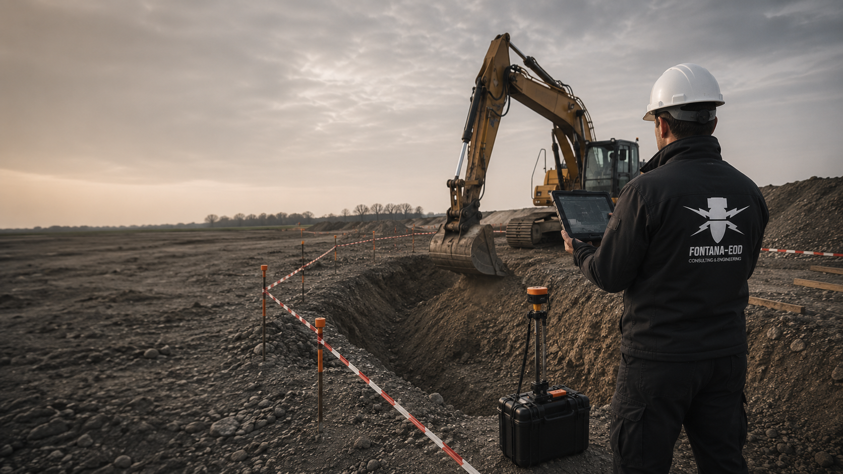
The documentation distinguishes previously investigated, supervised and outstanding areas.
Prepare sections for investigation alongside construction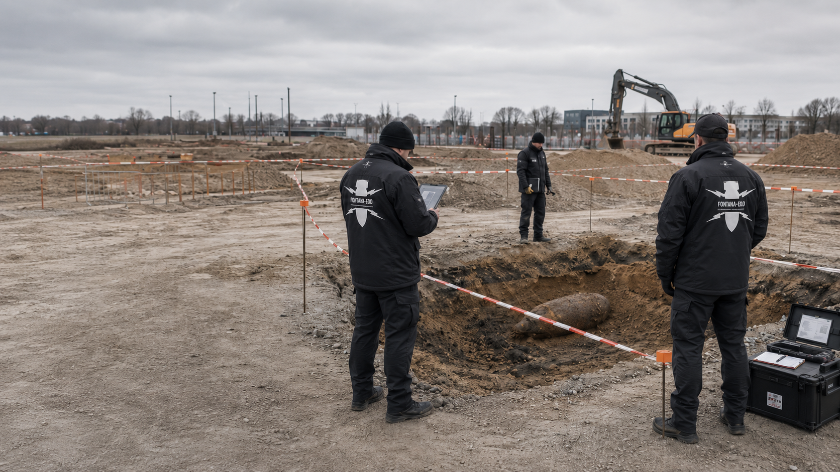
The project file documents the investigation and the decision on further action.
Clarify investigation of findings with specialist input
Site management and subsequent trades receive a clear investigation status.
Organise phase and section documentation
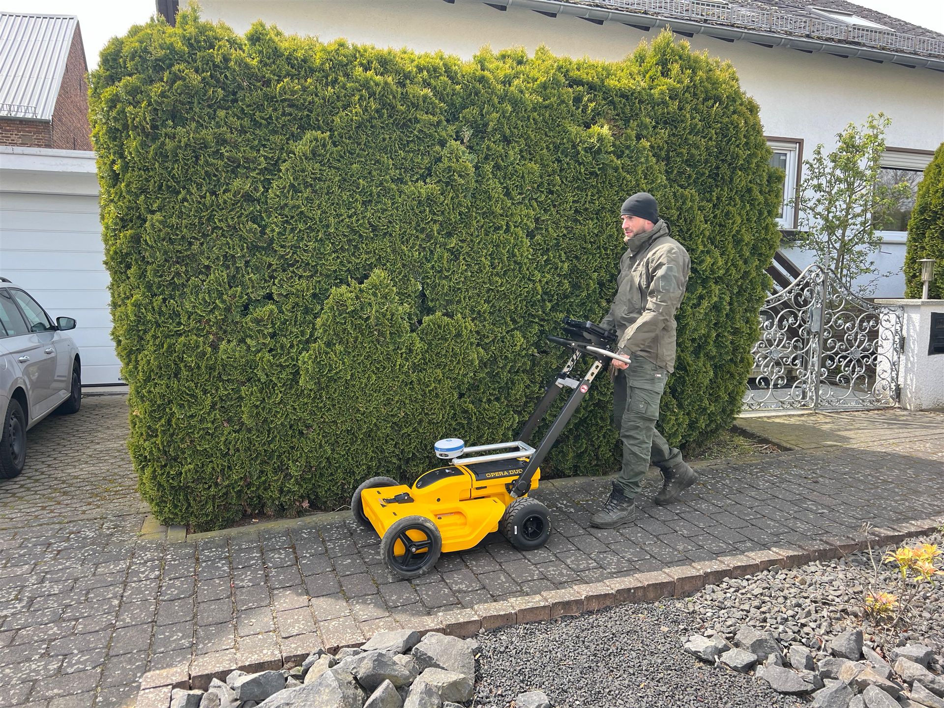
Historical clarification of suspicion, area and depth investigations, investigations alongside construction and documentation are related to the same junction and ramp geometry. For other construction tasks, see the Industry overview.
Plan road, sewer and civil engineering works involving crossings, drainage and foundations according to construction section and depth.
Assess the road construction context
Relate suspected areas, previous uses and outstanding data gaps to the complex traffic geometry.
Clarify the basis for suspicion at the junction
Plan area-wide surveys according to construction stage, surface and technical interference.
Define area-wide investigation volumes
Investigate deep individual points for masts, gantries, shoring and foundations by component.
Investigate foundation and shoring points
Assess whether an explosive ordnance survey alongside construction is suitable for the remaining areas.
Plan investigation alongside construction
Investigate specific findings traceably with their location, traffic phase and responsibility route.
Clarify the findings and handover process
Link construction phases, subareas, point lists and handovers in documentation that can be updated.
Organise phase and section documentation
Take account of local responsibilities and procedures for the specific project location.
Assess the project region with specialist inputAdd the road designation, junction or interchange name and ramp and junction-arm identifiers to the project location. Construction phase plans must show the same subareas as the investigation documents. Existing requirements and earlier reports are supplied with their actual spatial scope.
The specialist report describes the ground volume investigated and its limitations. Site management links this statement to traffic arrangements, utility works and the intended construction method. A statement for one ramp is not extended to other junction arms.
Check evidence against the interventionRelocated islands, new shaft positions or changed foundation points may lie outside the earlier investigation volume. Record these changes with their subarea identifiers and have the remaining applicability of results and necessary supplementary investigations checked before execution.
Explore the technical principlesTechnical information
How can carriageways, bridges and deep excavations be investigated for ordnance? The brochure explains preparation, suitable survey methods and supervision of earthworks.

Specialist assessment should begin once alignments, ramps, junction arms, construction phases and intended interventions are identifiable. For interchanges and complex junctions, the historically suspected hazard, carriageway extensions, islands, drainage, retaining walls, sign gantries, lighting, traffic signals and utility crossings must be brought together before tendering. This allows investigation requirements to be clearly defined by subarea, depth and construction stage.
Junctions consist of overlapping ground volumes: ramps, central islands, traffic islands, slopes, trenches, retaining structures, sign gantries and utility alignments. Near-surface survey areas do not automatically cover deep mast, pile, shoring or shaft points. For each component type, the area and depth actually requiring investigation are therefore assessed.
Temporary carriageways, diversions and section-by-section alterations change access and the ground volume of the works. An area may still carry traffic or be covered by structures at an early stage and become surveyable only later. Explosive ordnance investigation is therefore linked to traffic phases, demolition stages and handover dates. Earlier results remain usable only where the new construction geometry is fully covered.
If an unexpected suspicious object is found, stop work. Do not touch, move or uncover it further. Leave the immediate area and warn others without putting yourself at risk. In Germany, notify the police on 110; outside Germany, use the local emergency reporting procedure. The competent authorities determine what happens next; a project enquiry does not replace reporting the find.
Effort, duration and costs depend on the number and size of subareas, intervention depths, point foundations, surface, existing utilities, sources of interference and access. Traffic phases, work windows and required documentation affect the sequence. New ramps, relocated gantries or additional temporary works may require supplementary investigation. The site plan, traffic phases and depth lists are needed for the cost calculation.
If existing carriageways, utilities, structures or ongoing traffic prevent complete preliminary investigation, the technical suitability of an explosive ordnance survey alongside construction is assessed. Each working layer is surveyed using technical equipment and assessed before controlled removal in layers with supplementary visual inspection follows. These steps are repeated down to the agreed excavation base. Hold points, instruction routes, equipment deployment and documentation are defined before work begins. Necessary investigations and protective measures are also planned before groundworks during surface removal or demolition; areas not covered remain outstanding.
A clear spatial and chainage reference, assignment to a junction arm, ramp, island, structure or point object, the documented investigation geometry, methods used, technical limitations, anomalies, findings and follow-up decisions are required. For projects with several phases, plan revisions and partial handovers must remain traceable so that site management and subsequent trades can reliably use the current investigation status.
Useful documents include the site plan, junction and ramp geometry, construction phases, traffic management plans, working widths, excavation and foundation depths, point lists for masts and gantries, drainage and utility plans, ground investigation documents, historical assessments and the desired decision date. An early design revision is also suitable if options and agreed areas are clearly distinguished.
Information and requirements from authorities are supplied with their date, complete appendices and geographical scope. In Germany, the competent ordnance disposal service, local public-order authority and, where relevant, building-control authority are identified for the project location; outside Germany, local responsibilities apply.
An initial enquiry should identify the junction form, main construction phases, deep components and current plan revision.
Provide the site plan, alignments, ramps, junction arms, islands, structures and current revision.
Options and agreed execution areas should be clearly distinguished.
Include mast, gantry, shaft and shoring lists, together with drainage and utility alignments.
Target depths and installation methods affect the methodology.
Traffic phases, ground data, utility plans, historical assessment and earlier survey reports are useful.
State the date for design, tendering or execution.
A site plan, construction phase overview, junction or ramp geometry, maximum depth and existing indications of suspected ordnance are often sufficient for an initial review.
FONTANA-EOD then identifies the information still required and the appropriate scope of services for areas, points and remaining zones.
Junction arms, ramps, islands, structures and current plan revision.
Gantries, masts, shoring, shafts, foundations and target depths.
Traffic arrangements, demolition, access, closures and handover dates.
Basis for design, tendering, site management or the project file.
For large interchange programmes, an overarching status overview is recommended, recording ramps, structures, point foundations and outstanding remaining areas by construction phase. It supplements detailed reports without replacing their spatial and technical statements and makes coordination of several contract packages easier.
For interchanges with several parts, the documents should also show which contract packages, structures and technical installations are to be awarded together or separately. This affects subarea naming, point-list structure and which results must be combined in an overarching status overview.
Whether historical aerial photograph analysis, explosive ordnance surveying, surface surveying using GPR, magnetometry or TDEM, deep-ground surveys, downhole surveys, excavation supervision, area clearance or ordnance recovery is needed depends on the location, ground disturbance, depth, ground and existing documents. An early ordnance assessment provides clarity for tendering, programming, occupational safety and construction.
FONTANA-EOD combines its Section 7 SprengG licence, specialists holding Section 20 SprengG certificates of competence, suitable survey and clearance methods, and traceable documentation. Send the site plan, depth of ground disturbance, construction phase and existing documents for an initial technical assessment.


